PDF_Installation LE v1.1.pdf - Maryland Metrics
PDF_Installation LE v1.1.pdf - Maryland Metrics
PDF_Installation LE v1.1.pdf - Maryland Metrics

Create successful ePaper yourself
Turn your PDF publications into a flip-book with our unique Google optimized e-Paper software.
Ringfeder® Locking Elements RfN 8006 / Type GSA<br />
<strong>Installation</strong> And Removal Instructions<br />
1 Ring feder Co rporation –Instructions <strong>LE</strong> v1.1<br />
Since the torque is transmitted by contact pressure and f riction between the<br />
frictional sur faces, the condition of the contact sur faces and the proper tightening<br />
of the lo cking scr ews are impo rtant.<br />
INSTALLATION<br />
Clamp Flange<br />
Hub<br />
Shaft<br />
1 Carefully clean and lightly oil the shaft, hub bor e, spacer sle eves and lo cking<br />
element s.<br />
Note: Do NOT use a Molybdenum Disulphide LUBRICANT (“MO LYKOTE” OR<br />
THE LIKE).<br />
2 Install the pa rts in the foll owing orde r:<br />
a Hub (the pl ay between hub bore and shaft af fects the t rue running of the<br />
hub).<br />
b Spacer sle eve to b ridge the undercut (if needed).<br />
c Outer ring/inner ring (both pa rts must slide on easily) . For one lo cking<br />
element install the outer ring first . Otherwis e, install the inner ring first.<br />
d Spacer sle eve and clamp flange or clamp ring (both pa rts should slide on<br />
easily).<br />
e Carefully oil the oking scr ew threads and head be ring su faces.<br />
Note: Do NOT use Molybdenum Disulph e.<br />
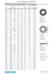
Figure 1: Tightening Sequence<br />
Tightening sequence for lo cking<br />
scr ews.
Ringfeder® Locking Elements RfN 8006 / Type GSA<br />
3 Tighten the lo cking scr ews evenly and in s everal steps foll owing the<br />
diamet rically opposite sequence illustrated i Figure n 1: Tightening Sequence.<br />
a Tighten the scr ews by hand until a slight positi ve contact is esta blished .<br />
Make final alignment adjustments to the connection.<br />
b Tighten the scr ews to appr ox. one-half the specified torque using an<br />
extended key or torque wrench.<br />
c Tighten the scr ews to full tightening torque using a torque wrench.<br />
d Verify that the scr ews are fully tightened by applying the specified torqu e.<br />
4 Check distance x . The clamp ring should not ma ke contact with the face of the<br />
hub. The gap between the clamp ring and hub face should be even all the way<br />
around.<br />
REMOVAL<br />
Note: Ring feder ® locking elements are not self-lo cking.<br />
1 Remove any accumulated contaminants from the connection.<br />
2 Loosen the lo cking scr ews in s everal stages foll owing a diamet rically opposite<br />
sequenc e.<br />
3 Remove the hub and lo cking elements from the shaft . If the lo cking element is<br />
jammed, loosen it by tapping it with a light hamme r.<br />
RINGFEDER Products are available from MARYLAND METRICS<br />
P.O. Box 261 Owings Mills, MD 21117 USA email: sales@mdmetric.com web: http://mdmetric.com<br />
phones: (410)358-3130 (800)638-1830 faxes: (410)358-3142 (800)872-9329<br />
Ring feder Co rporation –Instructions <strong>LE</strong> v1.1- E<br />
2