Hkkjr ljdkj jsy ea=ky; ekuo;qDr jsy leikj xsVksa gsrq lksyj ... - rdso
Hkkjr ljdkj jsy ea=ky; ekuo;qDr jsy leikj xsVksa gsrq lksyj ... - rdso
Hkkjr ljdkj jsy ea=ky; ekuo;qDr jsy leikj xsVksa gsrq lksyj ... - rdso

You also want an ePaper? Increase the reach of your titles
YUMPU automatically turns print PDFs into web optimized ePapers that Google loves.
Approved by<br />
Prepared by<br />
JE/EM<br />
lR;eso t;rs<br />
GOVERNMENT OF INDIA<br />
MINISTRY OF RAILWAYS<br />
<strong>Hkkjr</strong> <strong>ljdkj</strong><br />
<strong>jsy</strong> <strong>ea=ky</strong>;<br />
SOLAR PHOTOVOLTAIC BASED POWER SUPPLY FOR<br />
MANNED LEVEL CROSSING GATES<br />
<strong>ekuo</strong>;<strong>qDr</strong> <strong>jsy</strong> <strong>leikj</strong> <strong>xsVksa</strong> <strong>gsrq</strong> <strong>lksyj</strong><br />
QksVksoksYVsd vk/kkfjr ikWoj lIykbZ<br />
Draft Specification No. RDSO/PE/SPEC/PS/0076 (Rev. ‘0’) - 2012<br />
fof’kf"V la0% vkjMh,lvks@ihbZ@Lisd@ih,l@0076 ¼fjoh- ‘0’½&2012<br />
ISSUED BY-<br />
ENERGY MANAGEMENT DIRECTORATE<br />
RESEARCH DESIGNS AND STANDARDS ORGANISATION<br />
MANAK NAGAR, LUCKNOW- 226011<br />
Executive Director/ EM<br />
tkjhdrkZ&<br />
ÅtkZ izcU/ku funs’kky;<br />
vuqla/kku vfHkdYi ,oa ekud laxBu<br />
ekud uxj] y[kuÅ&226011<br />
Issued by<br />
DIR (EM)
Page 2 of 31 Draft dated 03.01.2013 Draft Spec. no. RDSO/PE/SPEC/PS/0076 (Rev.‘0’) - 2012<br />
Prepared by<br />
JE/EM<br />
I N D E X<br />
S. NO. DESCRIPTION PAGE NO.<br />
1.0 Foreword 3<br />
2.0 Scope 3<br />
3.0 Reference Standards 3<br />
4.0 System Description 3<br />
5.0 General Requirements 4<br />
6.0 Technical Requirements 5<br />
7.0 Installation & Commissioning 16<br />
8.0 Documentation 16<br />
9.0 Log Books 16<br />
10.0 Design Approval 17<br />
11.0 Prototype Approval 17<br />
12.0 Tests 17<br />
Annexure – 1 23<br />
Annexure – 2 25<br />
Annexure - 3 26<br />
Annexure – 4<br />
Issued by<br />
27<br />
DIR (EM)
Page 3 of 31 Draft dated 03.01.2013 Draft Spec. no. RDSO/PE/SPEC/PS/0076 (Rev.‘0’) - 2012<br />
DRAFT SPECIFICATION FOR SOLAR PHOTOVOLTAIC BASED POWER<br />
SUPPLY FOR MANNED LEVEL CROSSING GATES<br />
1.0 FOREWORD:<br />
The Sun is an inexhaustible, reliable and non-polluting source of power.<br />
Concerns over global climate change and resource scarcity make Solar<br />
Photovoltaic (SPV) with battery backup an attractive power supply solution for<br />
locations where grid power supply is not available. Such a system is therefore<br />
well suited for manned Level Crossing Gates in non-RE sections. It will greatly<br />
help towards the safety of road-rail intersections.<br />
2.0 SCOPE:<br />
This specification covers the general and technical requirements of solar<br />
photovoltaic system with battery backup, LED luminaires and fan for manned<br />
level crossing gates in non-RE sections.<br />
3.0 REFERENCE STANDARDS:<br />
IS: 12834:1989 (reaffirmed<br />
2000)<br />
Solar Photovoltaic Energy Systems - Terminology<br />
IEC : 61215 (2005) Crystalline silicon terrestrial photovoltaic (PV)<br />
modules – Design qualification and type approval<br />
IEC: 61730 Pt 1 & 2 Photovoltaic (PV) module safety qualification -Part<br />
1: Requirements for construction<br />
Part 2: Requirements for testing<br />
IEC:60904-1(2006) Photovoltaic Devices- Part-I: Measurement of<br />
Photovoltaic current-Voltage Characteristic<br />
IEC: 61701 Salt mist corrosion testing of photovoltaic (PV)<br />
modules<br />
IEC: 60068 Environmental testing<br />
IS:9000 Basic environmental testing procedure for<br />
Electronic and electrical items.<br />
Note: Latest version of the standards shall be referred to.<br />
4.0 SYSTEM DESCRIPTION:<br />
The Solar Photovoltaic (SPV) based system shall consist of the following<br />
elements:<br />
i) Rooftop mounted SPV Modules/ Array to convert solar radiation to<br />
electricity.<br />
ii) Module(s) mounting galvanized MS structure with necessary<br />
accessories.<br />
iii) Battery bank (to be installed inside the goomti) to store the electric<br />
energy generated by SPV panel during daytime.<br />
Prepared by<br />
JE/EM<br />
Issued by<br />
DIR (EM)
Page 4 of 31 Draft dated 03.01.2013 Draft Spec. no. RDSO/PE/SPEC/PS/0076 (Rev.‘0’) - 2012<br />
iv) Following chargers/ controllers will be provided:<br />
a) Solar charge controller (to be installed inside the goomti) to maintain the<br />
battery to the highest possible State of Charge (SOC) while protecting<br />
the battery from deep discharge (by the loads) or extended overcharge<br />
(by the PV array).<br />
b) A grid supplied charger (optional; to be installed inside the goomti) that<br />
can accept 140-260 Volts, 1-phase, 50 Hz AC as input and charge the<br />
battery (it is an optional item i.e. not to be supplied unless specifically<br />
called for in the tender).<br />
v) Blocking diode, preferably a Schottky diode, connected in series with<br />
solar cells and storage battery to keep the battery from discharging<br />
through the cell when there is no output or low output from the solar cell,<br />
if such diode is not provided with the module itself. In case any<br />
alternative to Schottky diode is proposed, then technical literature and<br />
evidence in support of successful working of the same should be<br />
submitted for the consideration of RDSO/ purchaser.<br />
vi) Either a 48V to 12V DC-DC converter or a 48VDC to 230V 50Hz AC<br />
inverter (to be installed inside the goomti), depending on whether the<br />
purchaser desires to supply the loads at 12V DC or 230V 50Hz AC.<br />
vii) LED luminaires (with fixtures) for the goomti’s illumination.<br />
viii) LED outdoor luminaires (with fixtures) along with poles.<br />
ix) Fan<br />
x) All copper wires/ cables and hardwares.<br />
5.0 GENERAL REQUIREMENTS:<br />
5.1 All wiring, enclosures and fixtures that are mounted outdoor must be resistant<br />
to high humidity conditions, corrosion, insect and dust intrusion.<br />
5.2 Metal equipment cases and frames in the system shall be properly grounded.<br />
5.3 The main components shall be integrated in such a way as to allow<br />
replacement (in case of failure) with a similarly functioning component of a<br />
newer design or a different brand.<br />
5.4 Suitable resettable isolating and overcurrent protection arrangements shall be<br />
incorporated. Toggle switches shall also be provided for switching ‘on’ and<br />
‘off’ of individual equipments.<br />
5.5 Proper sealing arrangements at the points of cables entering the enclosures<br />
(if any)/ buildings should be incorporated. Though not mandatory,<br />
manufacturers are however encouraged that the cables entering into the<br />
enclosures should be sealed with modular EPDM based cable sealing and<br />
protection system based on multi-diameter technology.<br />
Prepared by<br />
JE/EM<br />
Issued by<br />
DIR (EM)
Page 5 of 31 Draft dated 03.01.2013 Draft Spec. no. RDSO/PE/SPEC/PS/0076 (Rev.‘0’) - 2012<br />
5.6 Electronic components used in controller or elsewhere in the system shall<br />
generally meet the requirements mentioned as follows (documentary<br />
evidence in support of the same should be given):<br />
i) All capacitors shall be rated for max. temp of 105° C.<br />
ii) Resistances shall preferably be made of metal film of adequate rating<br />
having a tolerance of not more than 5%.<br />
iii) Switching devices such as transistors, IGBTs, MOSFETs, etc. shall<br />
have minimum junction temp. of 150° C.<br />
iv) Devices shall have adequate thermal margin at ambient temp. of 55° C.<br />
v) Fibre glass epoxy of grade FR 4 or superior shall be used for PCB<br />
boards having a nominal board thickness 1.6mm and copper cladding<br />
thickness of 70 microns for power cards and 35 microns for control<br />
cards. Both track width and spacing between the tracks shall be 0.5<br />
mm nominal and in no case shall be less than 0.3 mm. Assembled<br />
PCBs shall be given a conformal coating.<br />
5.7 Cables leading to outdoor lighting poles must not afford direct or easy access<br />
to non-railway persons. Cable crossing underneath the tracks shall be at a<br />
minimum depth of 1 m with respect to the top surface of sleeper. The cable<br />
laying arrangement is required to be maintenance friendly so that whenever<br />
cable replacement is warranted, the same can be carried out effortlessly i.e.<br />
simply by pulling out the failed cable. Towards this end, DWC pipes or other<br />
appropriate conduit can be utilized for cable laying.<br />
6.0 TECHNICAL REQUIREMENT:<br />
6.1 The SPV modules will feed DC power to a Solar Charge Controller. The<br />
charge controller will be required to charge 48V battery bank. If the<br />
purchaser does not specify anything to the contrary, then the system shall<br />
supply the loads with 12V DC. However, the purchaser can at his option<br />
specify that the loads be supplied at 230V 50Hz AC. In case of DC system, a<br />
48V to 12V DC-DC converter shall convert the 48V DC battery output to 12V<br />
DC and the lighting and fan loads shall work at a nominal voltage of 12V DC.<br />
In case of an AC based system, an inverter shall convert the 48V DC to 230V<br />
50Hz AC and the lighting and fan loads shall then work at a nominal voltage<br />
of 230V AC (refer item 5 (i) of Annexure-3).<br />
6.1.1 System load<br />
Load shall comprise of the following:<br />
i) 2 nos. 5W (nominal) LED based luminaires with fixtures, one inside goomti<br />
and one just outside the goomti under shed (working for 12 to 20 hours/day<br />
i.e. dusk to dawn).<br />
Prepared by<br />
JE/EM<br />
Issued by<br />
DIR (EM)
Page 6 of 31 Draft dated 03.01.2013 Draft Spec. no. RDSO/PE/SPEC/PS/0076 (Rev.‘0’) - 2012<br />
ii) 2 nos. 15W (nominal) LED luminaires with fixtures for illuminating the space<br />
between the level crossing gates and the road stretches exiting from the level<br />
crossing gates i.e. one luminaire on the same side as goomti and the other<br />
one across the tracks. The 15W luminaires will be mounted on individual<br />
poles (working for 12 hours/day i.e. dusk to dawn).<br />
iii) 1 no. 20W (nominal) fan inside goomti (working for 24 hours/day in summers).<br />
6.1.2 The design of solar based power supply is based on the following factors:<br />
i) Battery autonomy: 3 (1+2) days; depending on site requirement, the<br />
purchaser can opt for lesser/ higher autonomy, in which case battery<br />
capacity requirement will get modified accordingly.<br />
ii) Operation period for indoor lighting: almost 20 hours.<br />
iii) Operation period for outdoor lighting: almost 12 hours.<br />
iv) Operation period for fan: almost 24 hours (in summer)<br />
v) Solar Insolation: 5 peak sun hours/day<br />
6.2 SPV Modules, their structure and associated accessories:<br />
6.2.1 The solar module shall be an assembly of suitable inter-connected crystalline<br />
silicon solar cells. Imported SPV module or cell will not be accepted, unless<br />
MNRE’s policy/ rules permit the same.<br />
6.2.2 Minimum total capacity of the solar panels installed shall be 640 Wp. Solar<br />
modules of minimum 80 Wp capacity shall be used.<br />
6.2.3 Individual Solar PV Module should conform to IEC:61215 Ed 2 or latest –<br />
Edition II, IEC : 61730 – I :2007, IEC : 61730 – II : 2007, manufactured in a<br />
plant certified under ISO 9001 : 2008 and also type tested by an accredited<br />
national/international testing laboratory. The Solar PV Module should be<br />
made from single/poly crystalline Silicon Solar Cell connected in series. PV<br />
modules to be used in a highly corrosive atmosphere (coastal areas, etc.)<br />
must qualify Salt Mist Corrosion testing as per IEC 61701; this compliance<br />
and certification will not be required, unless the purchaser specifically asks for<br />
the same in the tender (refer item 2(i) in Annexure - 3).<br />
6.2.4 SPV modules of similar output with ± 2% tolerance in single string shall be<br />
employed to avoid array mismatch losses.<br />
6.2.5 The conversion efficiency of Solar PV Cells used in the module shall not be<br />
less than 15% and that of the module shall be not less than 13%.<br />
6.2.6 Fill factor of the module shall not be less than 72%.<br />
6.2.7 The solar module should have toughened, high transmissivity glass in front<br />
side of the module for improved visibility and protection against environmental<br />
Prepared by<br />
JE/EM<br />
Issued by<br />
DIR (EM)
Page 7 of 31 Draft dated 03.01.2013 Draft Spec. no. RDSO/PE/SPEC/PS/0076 (Rev.‘0’) - 2012<br />
hazards (rain, hail and storm) and weather proof TEDLAR/POLYSTER back<br />
sheet.<br />
6.2.8 The transparency of toughened glass used shall be > 91%, when measured in<br />
actual sunlight by placing the glass plate perpendicular to the sun’s rays<br />
through an air mass of 1.5. Certificate to this effect from a recognized test<br />
house or their own laboratory shall be submitted at the time of type approval.<br />
6.2.9 The complete solar module shall be ensured for water-proof sealing in an<br />
anodized Aluminum frame.<br />
6.2.10 The output terminals of the module shall be provided on the back of the<br />
solar PV module.<br />
6.2.11 Terminal block shall be made of Noryl rubber or other suitable alternate<br />
materials with weatherproof design (minimum IP-65) and shall have a<br />
provision for opening/ replacing the cables, if required.<br />
6.2.12 The system shall be virtually maintenance free (except for cleaning the top<br />
glass of the solar panel depending on dust conditions at place of<br />
installation).<br />
6.2.13 The solar cell shall have surface anti-reflective coating to help to absorb<br />
more light in all weather conditions.<br />
6.2.14 A bird spike shall be provided to avoid bird sitting on the solar module at the<br />
highest point of the array/ module structure.<br />
6.2.15 SPV module shall be highly reliable, lightweight and shall have a service life<br />
of more than 25 years. SPV modules shall have a limited power loss of not<br />
more than 10% of nominal output at the end of 10 years and not more than<br />
20% at the end of 25 years.<br />
6.2.16 Wherever more than one module is required, identical modules shall be<br />
used.<br />
6.2.17 The rated output of any supplied module shall not vary by more than 3%<br />
from the rated power of the module. Each module, therefore, has to be<br />
tested and rating displayed.<br />
6.2.18 The module junction boxes (if any) shall be certified as per IEC 61215. Else,<br />
they should have the same properties as mentioned for array junction<br />
boxes. Array junction boxes shall have the following properties:<br />
a) The module/array junction boxes shall be dust, vermin- and waterproof<br />
and made of Polycarbonate - Glass Fibre Substance (PC-GFS)<br />
thermoplastic. The enclosure should be double insulated with protection<br />
class II as per IEC 61439-1. Material and the protection class shall be<br />
marked on the enclosure.<br />
Prepared by<br />
JE/EM<br />
Issued by<br />
DIR (EM)
Page 8 of 31 Draft dated 03.01.2013 Draft Spec. no. RDSO/PE/SPEC/PS/0076 (Rev.‘0’) - 2012<br />
b) The enclosure shall have a transparent front lid for enabling easy visibility.<br />
c) The enclosures shall have IP 65/66 protection in accordance with IEC<br />
60529. Third party conformance certificate is required to be given for IP<br />
65/ IP 66 degree of protection.<br />
d) Burning Behavior: Base part of Polycarbonate Enclosure shall be UL-94-<br />
V-0 compliant and Lid part of PC Enclosure shall be UL-94-V-2 compliant.<br />
e) The enclosures shall have IK 08 degree of protection for mechanical load.<br />
f) The material used shall be halogen, silicon free conforming to RoHS<br />
directive 2002/95/EC.<br />
g) The enclosure shall have a usage temperature rating of -10C to 55C.<br />
h) The enclosure should be chemically resistant to acid, lye, petrol, mineral<br />
oil and partially resistant to benzene.<br />
i) The material of the enclosure shall be UV stabilized.<br />
Unless otherwise stipulated, the properties mentioned above should be<br />
demonstrated through datasheet of the manufacturer.<br />
6.2.19 The Array Junction Box should preferably have maximum 08 input and 01<br />
output with SPD/MOV and Terminal block.<br />
6.2.20 Suitable markings shall be provided on the bus bar for easy identification<br />
and cable ferrules shall be fitted at the cable termination points for<br />
identification. Cable entry points shall be fitted with MC-4 Connectors.<br />
6.2.21 The solar module shall be able to withstand the following environmental<br />
conditions normally encountered at site:<br />
i) Temp. ranging from -10C to +85C.<br />
ii) Wind load: 200 km/h.<br />
iii) Maximum mean hourly rainfall of 40 mm.<br />
iv) Humidity level upto 95%.<br />
6.2.22 Each PV module must use a RF identification tag (RFID), which must<br />
contain the following information. The RFID can be inside or outside the<br />
module laminate, but must be able to withstand harsh environmental<br />
conditions.<br />
i) Name of the manufacturer of PV Module<br />
ii) Name of the Manufacturer of Solar cells<br />
iii) Month and year of manufacture (separately for solar cells and module)<br />
iv) Country of origin (separately for solar cells and module)<br />
v) I-V curve for the module<br />
vi) Peak Wattage, Im, Vm and FF for the module<br />
vii) Unique Serial No and Model No of the module<br />
viii) Date and year of obtaining IEC PV module qualification certificate<br />
ix) Name of the test lab issuing IEC certificate<br />
x) Other relevant information on traceability of solar cells and module as<br />
per ISO 9000 series.<br />
Prepared by<br />
JE/EM<br />
Issued by<br />
DIR (EM)
Page 9 of 31 Draft dated 03.01.2013 Draft Spec. no. RDSO/PE/SPEC/PS/0076 (Rev.‘0’) - 2012<br />
6.2.23 Marking:<br />
Each module shall carry the following clear and indelible markings:<br />
i) Name, monogram or symbol of manufacturer;<br />
ii) Type or model number;<br />
iii) Serial number;<br />
iv) Polarity of terminals or leads (colour coding is permissible);<br />
v) Open circuit voltage;<br />
vi) Operating voltage;<br />
vii) Maximum system voltage for which the module is suitable;<br />
viii) Operating current;<br />
ix) Short circuit current;<br />
x) Date & place of manufacture;<br />
xi) Weight of the module.<br />
6.2.24 The SPV Module and associated items shall be tested as per Clause 12.1,<br />
12.2 and 12.3 of the spec.<br />
6.2.25 The SPV modules shall normally be mounted on a structure which is<br />
designed to withstand a wind speed of 150 kmph. In coastal/ high wind<br />
areas, the support structure, design and foundation shall be designed to<br />
withstand wind speed upto 200 kmph. If the purchaser does not specify<br />
anything to the contrary, then 150 kmph wind withstanding capability shall<br />
be provided. For this compliance, contractor’s certificate of conformity will be<br />
accepted (refer Item 3 (ii) of Annexure-3).<br />
6.2.26 The array structure shall be made of hot dip galvanized MS angles of size<br />
not less than 35mmX35mmX5mm. The galvanization thickness shall be at<br />
least 85 microns. For coastal/ corrosive environments, the galvanization<br />
thickness shall be at least 120 microns. If the purchaser does not specify<br />
anything to the contrary, then galvanization thickness of 85 microns shall be<br />
provided (refer Item 3 (i) of Annexure-3).<br />
6.2.27 The foundation for module mounting structure shall be preferably 1:2:4 RCC<br />
construction or any other combination based on the local site conditions for<br />
which design details shall be submitted. The installation of SPV modules<br />
should not impact the waterproofing of the existing terrace structure. The<br />
contractor shall be responsible for restoring the waterproofing to its original<br />
condition and for provision of additional waterproofing in the areas where<br />
RCC blocks are secured on to the terrace.<br />
6.2.28 The clearance of the lowest part of the module structure and the developed<br />
ground level shall normally not be less than 200 mm. However, in<br />
exceptional cases, lower clearances may be allowed on case to case basis.<br />
6.2.29 In general, bolts, nuts, shims and other hardware should be zinc plated.<br />
Fasteners visible to the public shall generally be of stainless steel of grade<br />
SS 304. The generally applicable engineering principle will be that fasteners<br />
Prepared by<br />
JE/EM<br />
Issued by<br />
DIR (EM)
Page 10 of 31 Draft dated 03.01.2013 Draft Spec. no. RDSO/PE/SPEC/PS/0076 (Rev.‘0’) - 2012<br />
shall be equal to or of greater corrosion resistance than the most corrosion<br />
resistant metals being fastened.<br />
6.2.30 The array structure shall be grounded properly using earthing kit as per IS:<br />
3043-1987, tested and certified by CPRI or any government approved<br />
laboratory.<br />
6.3 Charge Controller, grid supplied charger and their integrated<br />
functioning:<br />
6.3.1 Solar charge controller:<br />
The Solar Charge Controller (SCC) will comply the following requirements:<br />
(i) Suitable for charging VRLA as well as LMLA battery.<br />
(ii) Suitable for receiving input from 640Wp solar PV system and<br />
charging the battery.<br />
(iii) The charge controller should generally comply IEC 62509. Set point<br />
accuracy of ±3% and self consumption of 0.2% shall be allowed.<br />
(iv) The charge controller should have IP 31 protection. Manufacturers are<br />
however encouraged to provide higher IP protection.<br />
(v) It should be capable of handling 120% of module’s rated current.<br />
(vi) MPPT technology is to be provided. Though not mandatory,<br />
manufacturers are encouraged to provide MPPT algorithm efficiency of<br />
98% or higher.<br />
(vii) Efficiency at rated output voltage and full load should not be less than<br />
90%. Even at less than full load, efficiency should not be less than 86%<br />
for up to 30% full load.<br />
(viii) Temperature compensated charging.<br />
(ix) Provision of blocking diode, preferably a Schottky diode, to prevent the<br />
battery from discharging itself through the SPV system/ charge<br />
controller. The current capacity of the blocking diode shall be 50%<br />
higher than the short circuit current at STC. The peak inverse voltage<br />
(PIV) of the diode shall be at least equal to the open circuit battery<br />
voltage. In case any alternative to Schottky diode is proposed, then<br />
technical literature and evidence in support of successful working of the<br />
same should be submitted for the consideration of RDSO/ purchaser.<br />
(x) On the SPV power source side, the charge controller shall be protected<br />
against lightning and surges. The SPD/MOVs used shall be rated for at<br />
least 10KA at 8/20 μSec. The voltage rating of the SPD/MOVs shall be<br />
at least 10% higher than the specified value of the SPV array.<br />
(xi) Protection shall also be provided against the following: battery<br />
overload, battery overcharge, short circuit and reverse polarity.<br />
Resettable reverse polarity protection should be provided. Although not<br />
mandatory, manufacturers are encouraged to provide auto resettable<br />
reverse polarity protection.<br />
Prepared by<br />
JE/EM<br />
Issued by<br />
DIR (EM)
Page 11 of 31 Draft dated 03.01.2013 Draft Spec. no. RDSO/PE/SPEC/PS/0076 (Rev.‘0’) - 2012<br />
(xii) Cable of suitable size shall be provided on both sides i.e. between<br />
panel and battery; and between battery and DC-DC converter/ inverter.<br />
(xiii) The charge controller shall incorporate the auto, bulk and float charging<br />
methods. Though not mandatory, manufacturers are however<br />
encouraged to provide equalization charging facility also.<br />
(xiv) The charge controller shall have insulation resistance of at least 50 MΩ.<br />
The test is to be performed between shorted DC output terminals and<br />
earth, shorted DC/AC input terminals and earth and shorted DC output<br />
terminals and shorted DC/AC terminals.<br />
(xv) The charge controller shall withstand a test voltage of 2,000V applied<br />
between DC line terminals and earth for one minute without any<br />
puncture and arcing.<br />
(xvi) In case the master controller is not provided, then the charge controller<br />
should have the feature of load disconnect to protect the battery from<br />
deep discharge.<br />
(xvii) The charge controller should comply the following environmental tests<br />
with the charge controller working at full load for at least last half an<br />
hour as per IEC 60068/ IS 9000. Environmental test results for solar<br />
charge controller of identical or any higher capacity of similar design<br />
will be acceptable.<br />
a) Dry Heat Test: 50C±2C for 16 hours<br />
b) Damp Heat Test (Steady state): 40C, 93% RH for 4 days<br />
c) Damp Heat Test (Cyclic): 40C, 93% RH for 6 cycles (duration of<br />
one cycle shall be 24hrs)<br />
d) Cold Test: 0C for 16 hours<br />
e) Change of temperature Test: -10C to 50C for 3 cycles (rate of<br />
change of temperature shall be 3 o C per minute)<br />
6.3.2 Grid supplied charger (optional item):<br />
If grid electricity supply is available at a level crossing gate, then the<br />
purchaser can (optionally) order a battery charger which would be fed from<br />
grid electricity supply. The charger will work with 140 – 260V, 50 Hz AC input,<br />
will be based on PWM technology and shall be suitable for charging the<br />
battery as per the various stages of battery charging as mentioned in the<br />
aforesaid technical requirements for solar charge controller. Input to the<br />
charger shall be protected against lightning and surge. Unless specifically<br />
asked for by the purchaser in the tender, the aforesaid grid fed battery<br />
charger will not be supplied (refer Item no. 4(i) of Annexure-3).<br />
6.3.3 Integrated functioning of charge controller and charger:<br />
It will be necessary that the aforesaid charge controller as also the grid fed<br />
charger (if provided) maintain the battery to the highest possible State of<br />
Charge (SOC) while protecting the battery from deep discharge or extended<br />
overcharge. Even where a grid fed charger is provided, in as far as possible,<br />
renewable energy will be utilized for battery charging. But if the battery’s<br />
state of charge drops below a point, then the battery would be charged<br />
Prepared by<br />
Issued by<br />
JE/EM<br />
DIR (EM)
Page 12 of 31 Draft dated 03.01.2013 Draft Spec. no. RDSO/PE/SPEC/PS/0076 (Rev.‘0’) - 2012<br />
through the grid power supply; it should be possible for the purchaser to set<br />
the battery voltage at which the grid fed charger will cut in. The charge<br />
controller and grid fed charger (if any) should function in an integrated<br />
manner and without necessitating manual operation. Wherever necessary, a<br />
master controller (or functionality thereof) shall be provided towards this end.<br />
The controller shall have dusk to dawn switching for outdoor lighting.<br />
6.3.4 Indications and meters:<br />
Relevant meters should be provided for voltage of battery and indication<br />
through LED for Low Battery, Battery on charge and Battery fully charged.<br />
Detailed scheme shall be submitted at design/ drawing approval stage.<br />
6.4 Voltage Converters<br />
Unless otherwise specified by the purchaser, a system suitable for 12V DC<br />
loads will be supplied. However, the purchaser can at his option specify a<br />
system suitable for 230V 50Hz AC loads (refer Item 5 (i) of Annexure-3). In<br />
case of 12V DC based loads, a 48V to 12V DC-DC converter shall be<br />
provided. In case of 230V 50Hz AC loads, an inverter shall be provided to<br />
convert the 48V DC to 230V AC.<br />
6.4.1 48V to 12V DC-DC Converter:<br />
6.4.1.1 The 48V to 12V converter shall convert 48V DC received from charge<br />
controller output to 12V DC i.e. the voltage at which the loads (LED<br />
luminaires and fan) shall function.<br />
6.4.1.2 Output current handling capacity shall be at least 10A.<br />
6.4.1.3 The converter shall have a minimum efficiency of 88% for currents ranging<br />
from 2A to less than 5A and 90% from 5A to the maximum current rating.<br />
The manufacturers are however encouraged to provide higher efficiencies,<br />
preferably in the range of 95%.<br />
6.4.1.4 Protection shall be provided against the following: overload, short circuit<br />
and reverse polarity. Resettable reverse polarity protection should be<br />
provided. Although not mandatory, manufacturers are encouraged to<br />
provide auto resettable reverse polarity protection.<br />
6.4.1.5 The output ripple shall not be more than ±3% when measured at 10A<br />
output. The manufacturers are however encouraged to offer lower ripple<br />
content, preferably in the range of ±1%.<br />
6.4.2 48V DC to 230 AC Inverter<br />
6.4.2.1 The 48V DC to 230V 50Hz AC inverter shall convert 48V DC received<br />
from charge controller output to 230V AC i.e. the voltage at which the<br />
Prepared by<br />
JE/EM<br />
Issued by<br />
DIR (EM)
Page 13 of 31 Draft dated 03.01.2013 Draft Spec. no. RDSO/PE/SPEC/PS/0076 (Rev.‘0’) - 2012<br />
loads (LED luminaires and fan) shall function. It shall be an<br />
IGBT/MOSFET based high frequency sine wave inverter.<br />
6.4.2.2 The output power rating shall be 100VA at 0.8 power factor (PF).<br />
6.4.2.3 The inverter shall have a minimum efficiency of 85% at 70% of the load<br />
(resistive).<br />
6.4.2.4 The output voltage regulation shall be less than 3% at full load.<br />
6.4.2.5 The output frequency shall be 50Hz ± 0.5Hz.<br />
6.4.2.6 The THDv shall be less than 5% and THDi shall be less than 7%.<br />
6.4.2.7 The crest factor shall be better than 3:1.<br />
6.4.2.8 The inverter shall have galvanic isolation through an output transformer.<br />
6.4.2.9 The inverter shall have inbuilt forced air cooling arrangement. Naturally<br />
cooled inverter shall also be acceptable.<br />
6.4.2.10 The inverter shall have minimum IP21 protection.<br />
6.4.2.11 The inverter shall have following protection features: automatic shutdown<br />
against overloads, low battery voltage and high battery voltage; protection<br />
against over frequency and under frequency; and protection against over<br />
current and under current at both input and output.<br />
6.4.2.12 The input and output terminals of the inverter shall be accessible outside<br />
the inverter enclosure and closed with protective covers.<br />
6.4.2.13 The output of the transformer shall be protected against lightning.<br />
6.4.2.14 The inverter should comply the following environmental tests with the<br />
inverter working at full load for at least last half an hour as per IEC 60068/<br />
IS 9000. Environmental test results for inverter of identical or any higher<br />
capacity of similar design will be acceptable. Environmental test<br />
compliance will only be required, if specifically asked for in the tender<br />
(refer item 6 (i) of Annexure-3). In respect of bulk procurements, railways<br />
should ask for the same in their tenders.<br />
a) Dry Heat Test: 50C±2C for 16 hours<br />
b) Damp Heat Test (Steady state): 40C, 93% RH for 4 days<br />
c) Damp Heat Test (Cyclic): 40C, 93% RH for 6 cycles (duration of one<br />
cycle shall be 24hrs)<br />
d) Cold Test: 0C for 16 hours<br />
e) Change of temperature Test: -10C to 50C for 3 cycles (rate of<br />
change of temperature shall be 3 o C per minute).<br />
Prepared by<br />
JE/EM<br />
Issued by<br />
DIR (EM)
Page 14 of 31 Draft dated 03.01.2013 Draft Spec. no. RDSO/PE/SPEC/PS/0076 (Rev.‘0’) - 2012<br />
6.5 Battery Bank:<br />
Unless otherwise specified by the purchaser, Battery Bank shall be Tubular<br />
Gel Valve Regulated Lead Acid Battery (VRLA) type complying IEC 60896 21<br />
& 22. Gel tubular VRLA battery (when compared to the other type of VRLA<br />
battery) offers higher life in terms of cycles as well as years, there is far lower<br />
probability of PCL 3 effect, far lower risk of thermal runaway/ dry out failures<br />
and its capacity as well as internal resistance is relatively stable during<br />
lifetime. Flooded battery is not recommended as it requires topping up and<br />
moreover, it generates acid fumes (a health hazard for unventilated small<br />
indoor living spaces) as well as gases. The purchaser may at his option<br />
decide to specify any other type of battery, if considered necessary (refer item<br />
1(i) of Annexure-3).<br />
6.5.1 Unless otherwise specified by the purchaser, the storage battery bank rating<br />
shall be 48V 100Ah (C10). The purchaser can at his option, depending on site<br />
requirements, specify a lower/ higher Ah capacity of the battery (refer item<br />
1(ii) of Annexure-3).<br />
6.5.2 The battery shall have a design life expectancy of more than 5 years at 50%<br />
DOD at 27°C.<br />
6.5.3 The permissible self-discharge rate shall be less than 2% for T-gel VRLA<br />
batteries of the rated capacity per month at 27°C.<br />
6.5.4 The charging instructions shall be provided along with the batteries.<br />
6.5.5 The T-gel type VRLA batteries shall be discharged up to 80% DOD.<br />
6.5.6 Suitable Battery Box made of Polycarbonate or M.S. fabricated with acid proof<br />
paint shall be provided to house the battery.<br />
6.5.7 Make of the battery shall be finalized at the system design stage.<br />
6.6 Battery Testing:<br />
Tubular Gel batteries shall have third party certifications for life test as per IEC<br />
61427 for minimum requirement of 13 units @150cycles / unit equaling to 5<br />
years life. All routine tests as per applicable standards shall be conducted on<br />
the batteries.<br />
Performance characteristics curves as indicated below of the offered battery<br />
shall be submitted:<br />
i) Charging-discharging characteristics at various temperature and cell voltage.<br />
ii) Self discharge at various ambient temperatures.<br />
iii) Cell voltage vs. State of charge.<br />
Prepared by<br />
JE/EM<br />
Issued by<br />
DIR (EM)
Page 15 of 31 Draft dated 03.01.2013 Draft Spec. no. RDSO/PE/SPEC/PS/0076 (Rev.‘0’) - 2012<br />
iv) Capacity vs. Rate of discharge.<br />
v) State of charge vs. Sp. Gravity of electrolyte.<br />
vi) Depth of discharge vs. No. of cycles.<br />
6.7 LED Lamp and Fixtures:<br />
Instead of designing/ manufacturing a special luminaire, a commercially<br />
available LED luminaire (or an improved version of it) of good repute/<br />
performance record, if available, will be preferable. Unless otherwise specified<br />
in the following sub-clauses, LED/ luminaire manufacturer’s data-sheet/<br />
conformance certificate will be accepted in lieu of tests.<br />
6.7.1 Rated Voltage and Power: Voltage: 12V DC or 230V AC (as specified in the<br />
tender); Power: 15W nominal for outdoor and 5W nominal for indoor (power<br />
ratings are inclusive of driver losses).<br />
6.7.2 Minimum efficacy of the luminaires shall be 80 lumen/W i.e. minimum 400 (for<br />
5W)/ 1200 (for 15W) system lumens. Third party certificates for compliance<br />
can be accepted. Else, this is required to be demonstrated through a test.<br />
6.7.3 For outdoor luminaires, LM 79 report is required to be submitted. Else, this is<br />
required to be demonstrated through a test.<br />
6.7.4 LED type – White LEDs with CCT range of 5500-6500 K temperature<br />
(preferably surface mount power LEDs). Colour Binning should comply<br />
existing ANSI standard C78.377A. White Point Stability of LED should be<br />
within 7 McAdam Step. LED used should be of SMD type only.<br />
6.7.5 Colour Rendering Index (CRI) of the LEDs used shall be 70 (nominal).<br />
6.7.6 Minimum LED efficacy shall be 100 lm @ 350mA drive current to meet<br />
required LUX level. Nominal viewing angle of the LEDs used shall be 120°.<br />
6.7.7 L70 life of LED shall be more than 50,000 hours at soldering point<br />
temperature of 85 deg C and at luminaire operating current. The life time<br />
projection should be based on LM-80 test data and corresponding TM21<br />
projection method for the corresponding driving currents at which the LEDs<br />
are driven.<br />
6.7.8 Junction to soldering point thermal resistance of the LED used should be less<br />
than 10 degC/W for outdoor luminaires.<br />
6.7.9 LED used shall be of NICHIA/ OSRAM/ SEOUL SEMICONDUCTOR/<br />
PHILLIPS LUMILEDS/ LEDNIUM/ CREE make.<br />
6.7.10 Outdoor LED fixing arrangement - Mounted on metal core PCB fixed to<br />
Aluminum heat sink for 15W luminaire.<br />
Prepared by<br />
JE/EM<br />
Issued by<br />
DIR (EM)
Page 16 of 31 Draft dated 03.01.2013 Draft Spec. no. RDSO/PE/SPEC/PS/0076 (Rev.‘0’) - 2012<br />
6.7.11 The 15W LED outdoor luminaires shall each be mounted on 5m height from<br />
ground level on galvanized 6m MS poles of nominal dia 3” with necessary<br />
accessories i.e. one luminaire on each of the two poles on either side of the<br />
track.<br />
6.7.12 Avg. illuminance delivered by outdoor luminaire shall be 4 lux at ground level<br />
(5m from the luminaire) and shall be measured using 9 point method as<br />
defined in Annexure 2. The ratio of minimum to average illumination shall be<br />
at least 0.4 and the transverse uniformity ratio i.e. minimum to maximum<br />
illumination shall be at least 0.33. Luminaires conforming to desired<br />
requirements will be acceptable. Third party certificates for compliance shall<br />
be accepted. Else, this is required to be demonstrated through a test.<br />
6.7.13 Indoor LED Fixture: ABS plastic/Aluminum fixture with acrylic cover.<br />
6.7.14 Outdoor LED Fixture: Pressure die-cast LM6 housing with IP65 protection,<br />
having toughened glass/ UV stabilized polycarbonate cover.<br />
6.7.15 The LED luminaire shall comply IEC 60598/ IS 10322. Third party certificates<br />
for compliance shall be accepted. Else, this shall be demonstrated through<br />
tests.<br />
6.7.16 The temperature of the heat sink shall not be greater than 20C above<br />
ambient temperature even after 6 hours of continuous operation. Further,<br />
soldering point temperature of the LEDs used in the luminaire shall also be<br />
demonstrated through a test.<br />
6.7.17 The LED driver DC current regulation shall be better than 3%.<br />
6.7.18 The LED control gear shall comply IS 15885 (Part 2 /Sec 13)/ IEC 61347-2-13<br />
and IS 16104/ IEC 62384. Third party certificates for compliance shall be<br />
accepted. Else, this shall be demonstrated through a test.<br />
6.7.19 Automatic dusk to dawn switching of the LED streetlights shall be integrated<br />
in the system. A separate switch and fuse arrangement for each LED light<br />
shall be provided inside the goomti for the purpose of safety and<br />
maintenance.<br />
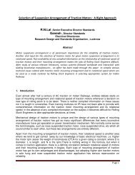
6.7.20 Typical light distribution for outdoor luminaire should be as per the following<br />
polar curve:<br />
Prepared by<br />
JE/EM<br />
Issued by<br />
DIR (EM)
Page 17 of 31 Draft dated 03.01.2013 Draft Spec. no. RDSO/PE/SPEC/PS/0076 (Rev.‘0’) - 2012<br />
6.8 Fan:<br />
A wall mounted bracket fan shall be provided. A commercially available<br />
market product of good repute/ performance record will be preferable. Unless<br />
otherwise specified, fan manufacturer’s data-sheet/ conformance certificate<br />
will be accepted in lieu of tests. Indicative technical parameters of the fan can<br />
be as follows. But if it so happens that a commercially available market<br />
product of good repute/ performance record has somewhat different<br />
parameters, the same can also be accepted by the purchaser with the overriding<br />
condition that the power consumption of fan will not exceed 25W in any<br />
case.<br />
Voltage rating: 12V DC/ 230V AC (as per system requirement)<br />
Power: 20W (nominal)<br />
Air flow: More than 0.25 m³/sec.<br />
Fan sweep: 300 mm<br />
Motor insulation: F Class<br />
Temp rise: less than 65° C above ambient.<br />
Public Safety: Shroud shall be provided for protection.<br />
6.9 Cables and Hardware:<br />
6.9.1 Cabling of the system shall be as short as possible to minimize the voltage<br />
drop in the wiring<br />
6.9.2 Cable shall meet IS 1554/ 694 Part 1:1988 and shall be of 650 V/ 1.1 kV.<br />
6.9.3 The module/ array wiring shall be water and UV resistant and suitable for<br />
Solar system application. The cables used shall be TUV 2Pfg 1169/08.2007<br />
or VDE EPV 01:2008-02 or UL4703 certified.<br />
Prepared by<br />
JE/EM<br />
Issued by<br />
DIR (EM)
Page 18 of 31 Draft dated 03.01.2013 Draft Spec. no. RDSO/PE/SPEC/PS/0076 (Rev.‘0’) - 2012<br />
6.9.4 All wiring must be sized to keep line voltage losses to less than 3% in each<br />
sub-circuit and to allow the circuit to operate within the ampere rating of the<br />
wire.<br />
6.9.5 Components and hardware shall be vandal and theft resistant. All parts shall<br />
be corrosion-resistant.<br />
6.10 Protections:<br />
6.10.1 Adequate protection shall be incorporated under no-load conditions (i.e. when<br />
the system is ON and there is no load) from master controller output side.<br />
6.10.2 If any other protection is necessary, the same will be deemed to be a part of<br />
the specification.<br />
6.11 Marking:<br />
Each system shall carry the following clear and indelible markings on the<br />
controller:<br />
- Name, monogram or symbol of system integrator;<br />
- Type or model number;<br />
- Serial number;<br />
- Polarity of terminals or leads (colour coding is permissible);<br />
- Output voltage.<br />
- Max. Power output<br />
- Date of supply<br />
- Battery type<br />
- Total AH<br />
- No./ AH of batteries<br />
7.0 INSTALLATION & COMMISSIONING:<br />
The installation shall be done by the supplier/manufacturer who is responsible<br />
for system performance, direction of installation and structural stability. The<br />
supplier shall conduct a detailed site assessment. The installer shall obtain<br />
data specific to the site, rather than relying on general data.<br />
8.0 DOCUMENTATION:<br />
The supplier shall provide easy-to-use illustrated installation and operation<br />
manual in English and local language for easy installation and trouble-free<br />
usage. The manual shall contain complete system details such as array<br />
layout, schematic of the system, working principle, clear instruction on regular<br />
maintenance, troubleshooting of the system and emergency shutdown<br />
procedures.<br />
Prepared by<br />
JE/EM<br />
Issued by<br />
DIR (EM)
Page 19 of 31 Draft dated 03.01.2013 Draft Spec. no. RDSO/PE/SPEC/PS/0076 (Rev.‘0’) - 2012<br />
9.0 LOG BOOKS:<br />
Railways shall maintain a logbook detailing inspection and operating<br />
activities. This log book must be kept in a secure place and shall be made<br />
available, whenever required for inspection. Testing of all protection devices<br />
shall be carried out at regular intervals (no longer than six months) by the<br />
customer and recorded in the log book.<br />
10.0 DESIGN APPROVAL:<br />
Design for complete system and sub-systems shall be approved by RDSO at<br />
design stage before manufacture of prototype conforming to this specification.<br />
The criteria for selection of sub-system / component shall be based on sound<br />
engineering practice conforming to the International/ Indian Standards<br />
wherever specific standard is not specified in this specification. The detailed<br />
calculation/simulated results shall be submitted in support of system/subsystem<br />
rating. Adequate safety margin as stipulated in respective<br />
specification shall be used.<br />
11.0 PROTOTYPE APPROVAL:<br />
The prototype system shall be offered to RDSO for testing and approval. For<br />
certain tests, the type testing authority i.e. RDSO may choose to rely upon<br />
previous type test reports/conformance certificates, as long as they pertain to<br />
similar design and comparable rating. However, the manufacturer cannot<br />
demand this as a matter of right.<br />
Until the railways are able to issue their vendor list, they may in the interim<br />
period invite tender/ place order with the provision of accepting the material<br />
on the basis of firm’s written clause-by-clause confirmation of the spec. and<br />
acceptance test alone, wherever this is considered necessary by CEE.<br />
12.0 TESTS:<br />
The manufacturer shall carry out routine tests at his works and shall maintain<br />
records for the same. Acceptance testing shall be carried out by the<br />
purchaser or his representative or by any agency deputed by the purchaser<br />
on his behalf.<br />
12.1 Test on SPV Module:<br />
S.N. Name of Test Type Routine Acceptance Method<br />
Test Test Test<br />
1. Visual Examination √ √ √ Refer Annexure 1<br />
2. Design Qualification √ √ √* IEC 61215 and<br />
Cl. 6.2.3<br />
3. Safety Test √ √ √* IEC 61730 and<br />
Prepared by<br />
JE/EM<br />
Issued by<br />
DIR (EM)
Page 20 of 31 Draft dated 03.01.2013 Draft Spec. no. RDSO/PE/SPEC/PS/0076 (Rev.‘0’) - 2012<br />
4. Photo Electrical<br />
Conversion Efficiency<br />
Prepared by<br />
√<br />
JE/EM<br />
√<br />
Issued by<br />
√<br />
Cl. 6.2.3<br />
By Sun simulator<br />
on each module<br />
and Cl. 6.2.5<br />
5. Fill Factor √ √ √ By Sun simulator<br />
on each module<br />
and Cl. 6.2.6<br />
6. Transmitivity of Glass √ As per Cl 6.2.8<br />
7. Rated output of<br />
module<br />
√ √ √ By Sun simulator<br />
on each module<br />
and Cl. 6.2.2<br />
8. Module mismatch test √ √ Refer Cl 6.2.17<br />
9. Array mismatch test √ Refer Cl 6.2.4<br />
10. Terminal block √ √ ∑ Refer Cl 6.2.11<br />
11. Provision of Bird Spike √ √ Refer Cl 6.2.14<br />
12. Provision of RFID tag<br />
with requisite details<br />
√ √ √ Refer Cl 6.2.22<br />
13. Environmental tests √ √** Refer Annexure<br />
1<br />
14. Insulation Resistance √ √ Refer Annexure<br />
- 1<br />
15. Provision of Earthing √ √ Refer Cl 6.2.30<br />
16. Warranty Certificate<br />
for the modules<br />
√ √ Refer Cl 6.2.15<br />
17. Marking √ √ √ Refer Cl 6.2.23<br />
* Copy of the latest conformance certificates should be asked<br />
∑ To be relied on datasheets and test reports<br />
** If compliance has already been checked during type testing, the same will be relied upon,<br />
otherwise compliance will be ensured through physical tests<br />
12.2 Tests on Module Mounting Structure:<br />
S.N. Name of Test Type Routine Acceptance<br />
Test Test Test<br />
1. Visual Examination √ √ √<br />
2. Dimension √<br />
√<br />
Method<br />
As per<br />
manufacturer’s<br />
data sheet and<br />
Cl. 6.2.26<br />
DIR (EM)
Page 21 of 31 Draft dated 03.01.2013 Draft Spec. no. RDSO/PE/SPEC/PS/0076 (Rev.‘0’) - 2012<br />
3. Design calculation on<br />
module structure<br />
withstand capability<br />
4. Clearance between<br />
module and ground<br />
Prepared by<br />
JE/EM<br />
√<br />
Issued by<br />
√<br />
Refer Cl 6.2.25<br />
√ Refer Cl 6.2.28<br />
5. Galvanization thickness √ √ Refer Cl 6.2.26<br />
6. Foundation<br />
7. Fasteners<br />
√ Refer Cl 6.2.27<br />
√ Refer Cl 6.2.29<br />
12.3 Tests on module junction box, Array sub-main and main Junction Box:<br />
S.N. Name of Test Type Routine Acceptance Method<br />
Test Test Test<br />
1. Visual Examination √ √ √ Refer Cl 6.2.18,<br />
6.2.19, 6.2.20<br />
2. Material √ √ ∑ Refer Cl 6.2.18<br />
3. IP Protection √ √ Refer Cl 6.2.18<br />
4. Surge Protection √ √ ∑ Refer Cl 6.2.19<br />
5. Cable entry and<br />
markings<br />
∑ To be relied on datasheets and test reports<br />
12.4 Test on Solar Charge Controller:<br />
S.N. Name of Test Type Routine Acceptance<br />
Test Test Test<br />
1. Visual Examination √ √ √<br />
√ Refer Cl 6.2.20<br />
Method<br />
2. Compliance to IEC: √<br />
Refer Cl.<br />
62509<br />
6.3.1-(iii)<br />
3. Functionality and rating √ √ √ Refer Cl.<br />
of the charge controller<br />
6.3.1-(ii)<br />
4. Auto, bulk, float and √<br />
√<br />
equalization charging of<br />
battery<br />
€<br />
Refer Cl.<br />
6.3.1-(xiii)<br />
5. MPPT Technology √<br />
√ α<br />
Refer Cl.<br />
6.3.1-(vi)<br />
6. Capability for handling √ √<br />
120% of rated current<br />
α Refer Cl.<br />
6.3.1-(v)<br />
7. Insulation Resistance √ √ √ Refer Cl.<br />
6.3.1-(xiv)<br />
√ α<br />
DIR (EM)
Page 22 of 31 Draft dated 03.01.2013 Draft Spec. no. RDSO/PE/SPEC/PS/0076 (Rev.‘0’) - 2012<br />
8. Efficiency √ √ € Refer Cl.<br />
6.3.1-(vii)<br />
9. Temp. Compensation √ √ α Refer Cl.<br />
6.3.1-(viii)<br />
10. Protection Tests √ √ € Refer Cl.<br />
6.3.1-(xi) &<br />
(xvi)<br />
11. IP protection √ √ Refer Cl.<br />
6.3.1-(iv)<br />
12. Surge protection √ √ Refer Cl.<br />
6.3.1-(x)<br />
13. Self-Consumption Test √ √ € Refer Cl.<br />
6.3.1-(iii)<br />
14. Blocking Diode √ √ Refer Cl.<br />
6.3.1-(ix)<br />
15. Over Voltage Test √ √*** Refer Cl.<br />
6.3.1-(xv)<br />
16. Environmental Test √ √ α Refer Cl.<br />
17. Suitability for both T-<br />
Gel VRLA as well as<br />
LMLA<br />
18. Checking of electronic<br />
components<br />
19. Output to be cut-off on<br />
80% DOD of battery<br />
20. Master Controller &<br />
charger functionality (if<br />
any)<br />
6.3.1-(xvii)<br />
√ √ α Refer Cl.<br />
6.3.1-(i)<br />
√ √ ∂ Refer Cl 5.6<br />
√ √ Refer Cl. 6.5.5<br />
√ √ √ Refer Cl. 6.3.2<br />
& 6.3.3<br />
α<br />
If compliance has already been checked during type testing, the same will be relied upon,<br />
otherwise compliance will be ensured through physical tests<br />
€<br />
On random 5% of the samples or a minimum of 2 samples<br />
*** On any one random sample<br />
∂<br />
To be relied on datasheets and test reports<br />
12.5 Tests on DC-DC Converter<br />
S.N. Name of Test Type Routine Acceptance<br />
Test Test Test<br />
1. Visual Examination √ √ √<br />
Method<br />
2. Output current handling √ Refer Cl.<br />
capacity<br />
6.4.1.2<br />
3. Efficiency √ √<br />
Prepared by<br />
Issued by<br />
JE/EM<br />
DIR (EM)<br />
∆ Refer Cl.<br />
6.4.1.3<br />
4. Protection Tests √ √ π Refer Cl.<br />
6.4.1.4<br />
5. Ripple content √ √ π Refer Cl.<br />
6.4.1.5
Page 23 of 31 Draft dated 03.01.2013 Draft Spec. no. RDSO/PE/SPEC/PS/0076 (Rev.‘0’) - 2012<br />
∆<br />
If compliance has already been checked during type testing, the same will be relied upon, otherwise<br />
compliance will be ensured through physical tests<br />
π<br />
On random 5% of the samples or a minimum of 2 samples<br />
12.6 Tests on Inverter<br />
S.N. Name of Test Type Routine Acceptance<br />
Test Test Test<br />
1. Visual Examination √ √ √<br />
Prepared by<br />
JE/EM<br />
Issued by<br />
Method<br />
2. Output power rating √ Refer Cl.<br />
6.4.2.2<br />
3. Efficiency √ √ α Refer Cl.<br />
6.4.2.3<br />
4. Output Voltage<br />
√ √<br />
Regulation<br />
Ω Refer Cl.<br />
6.4.2.4<br />
5. Output Frequency √ √ Ω Refer Cl.<br />
6.4.2.5<br />
6. THDv, THDi √ √ Ω Refer Cl.<br />
6.4.2.6<br />
7. Crest Factor √ √ Ω Refer Cl.<br />
6.4.2.7<br />
8. Provision of Galvanic √ √<br />
Isolation<br />
Ω Refer Cl.<br />
6.4.2.8<br />
9. IP Protection √ √ Ω Refer Cl.<br />
6.4.2.10<br />
10. Protection Features √ √ Ω Refer Cl.<br />
6.4.2.11<br />
11. Lightning Protection √ √ Ω Refer Cl.<br />
6.4.2.13<br />
12. Environmental Tests √ √ α Refer Cl.<br />
6.4.2.14<br />
α<br />
If compliance has already been checked during type testing, the same will be relied upon, otherwise<br />
compliance will be ensured through physical tests<br />
Ω<br />
On random 5% of the samples or a minimum of 2 samples<br />
12.7 Tests on Battery:<br />
S.N. Name of Test Type Routine Acceptance<br />
Test Test Test<br />
1. Visual Examination √ √ √<br />
Method<br />
2. Battery Type √ √ Refer Cl. 6.5<br />
3. Battery Voltage and AH √ √ £ Refer Cl. 6.5.1<br />
4. Battery Life √ £ √ £ Refer Cl. 6.5.2<br />
5. Enclosure material √ √ √ Refer Cl. 6.5.6<br />
DIR (EM)
Page 24 of 31 Draft dated 03.01.2013 Draft Spec. no. RDSO/PE/SPEC/PS/0076 (Rev.‘0’) - 2012<br />
6. Self-Discharge Test √ £ √ £ Refer Cl. 6.5.3<br />
7. Battery Characteristics √ £ √ £ Refer Cl. 6.6<br />
£ To be relied on datasheets and test reports<br />
12.8 Tests on LED Lamp and Fixture:<br />
S.N. Name of Test Type Routine Acceptance<br />
Test Test Test<br />
1. Visual Examination √ √ √<br />
2. Rated Power of the<br />
luminaire<br />
√ √ √<br />
3. Light Intensity<br />
√<br />
√ ¥<br />
Method<br />
Refer Cl. 6.7.1<br />
Refer Cl. 6.7.2<br />
4. Lumen efficacy of the<br />
luminaire<br />
√ √ µ Refer Cl. 6.7.3<br />
5. LED Type √** √** Refer Cl. 6.7.4,<br />
6.7.5, 6.7.6,<br />
6.7.7, 6.7.8,<br />
6.7.9, 6.7.10<br />
6. LM-80 and TM-21<br />
reports for L70 Life of<br />
LEDs<br />
√** √** Refer Cl. 6.7.7<br />
7. Lux Level √ √ µ Refer Cl. 6.7.12<br />
8. LED Luminaire and its √ √ Refer Cl.<br />
fixture<br />
6.7.10, 6.7.11,<br />
6.7.13, 6.7.14<br />
and 6.7.15<br />
9. IP Protection √ √ ¥ Refer Cl. 6.7.14<br />
10. Heat Sink and soldering<br />
point temperature<br />
√ √ µ Refer Cl. 6.7.16<br />
11. LED Driver Regulation √ √ Refer Cl. 6.7.17<br />
12. LED Control Gear<br />
Compliance<br />
√ √ ¥ Refer Cl. 6.7.18<br />
13. LED luminaire testing √ √ ¥ Refer Cl. 6.7.15<br />
14. Dusk to Dawn<br />
Switching<br />
√ √ µ Refer Cl. 6.7.19<br />
15. LM-79 Compliant and<br />
polar curve<br />
√ ¥ √ ¥ Refer Cl. 6.7.20<br />
16. Checking of electronic<br />
components<br />
√ √ ** Refer Cl 5.6<br />
¥ Checking of test reports<br />
** Checking of datasheets<br />
µ On random 5% of the samples or a minimum of 2 samples<br />
12.9 Tests on Cables and Hardware:<br />
S.N. Name of Test Type Routine Acceptance Method<br />
Prepared by<br />
Issued by<br />
JE/EM<br />
DIR (EM)
Page 25 of 31 Draft dated 03.01.2013 Draft Spec. no. RDSO/PE/SPEC/PS/0076 (Rev.‘0’) - 2012<br />
Test Test Test<br />
1. Visual Examination √ √<br />
√<br />
2. Voltage rating √ √ Refer Cl 6.9.2<br />
3. Voltage Drop Test √ Refer Cl 6.9.4<br />
4. Module/ array wiring √<br />
5. Type and size of cable<br />
connecting the charge<br />
controller<br />
12.10 Test on Fan:<br />
Prepared by<br />
JE/EM<br />
Issued by<br />
√<br />
Refer Cl 6.9.3<br />
√ √ Refer Cl 6.3.1 (xii)<br />
During acceptance of the system, the fan should be visually examined, its<br />
rating plate should be checked for correctness of voltage, power, motor<br />
insulation, air flow, sweep and the fan should be subjected to a simple<br />
functional check. Only power consumption at rated voltage should be<br />
measured.<br />
DIR (EM)
Page 26 of 31 Draft dated 03.01.2013 Draft Spec. no. RDSO/PE/SPEC/PS/0076 (Rev.‘0’) - 2012<br />
Quality Testing of PV-Module:<br />
Prepared by<br />
JE/EM<br />
Issued by<br />
Annexure - 1<br />
Solar PV module shall be certified according to IEC 61215. The qualification testing<br />
procedure is defined in IEC 61215 to examine the impact of mechanical, thermal and<br />
electrical stress on power output. Bidder shall submit appropriate type approval<br />
certificate for the offered solar modules from IEC accredited laboratories.<br />
Method of Testing:<br />
1.0 Visual Inspection:<br />
Each module shall be carefully inspected under an illumination of not less<br />
than1000 lux for the following conditions:<br />
i) cracked, bent, misaligned or torn external surfaces<br />
ii) broken/ cracked cells<br />
iii) faulty interconnections or joints<br />
iv) cells touching one another or the frame<br />
v) failure of adhesive bonds, bubbles or delaminations forming a<br />
continuous path between a cell and edge of the module<br />
vi) faulty terminations, exposed live electrical parts<br />
vii) Junction box should have common terminals with suitable bypass<br />
diode for preventing hot spot problem.<br />
2.0 Performance at STC: (Clause 10.1 of IEC 61215:2005)<br />
The current-voltage characteristics of the module shall be determined in<br />
accordance with IEC 60904-1 at a specific set of irradiance and temperature<br />
conditions.<br />
Performance of PV-Module shall be generally evaluated at Standard-Test-<br />
Conditions (STC) as defined in IEC 60904 standards:<br />
i) cell temp of 25° C,<br />
ii) incident solar irradiance of 1000W/m2,<br />
iii) spectral distribution of light spectrum with an air mass AM=1.5<br />
3.0 Environmental Testing:<br />
Following environmental tests shall be conducted on offered module or on<br />
module of similar design, for initial clearance of the offered system:<br />
Test Test Details Relevant standards<br />
Cold Test Temp. (-) 10 0 C<br />
Duration: 16 hrs.<br />
IEC-68-2-1<br />
Dry Heat Temp. (+) 70 0 C IEC-68-2-2<br />
DIR (EM)
Page 27 of 31 Draft dated 03.01.2013 Draft Spec. no. RDSO/PE/SPEC/PS/0076 (Rev.‘0’) - 2012<br />
Duration: 16 hrs<br />
Salt spray *<br />
Temp. (+) 35 0 C, RH<br />
95%<br />
Duration: 2 hrs spray<br />
and 22 hrs conditioning<br />
No. of Cycle : 01<br />
Wind Pressure equivalent to<br />
an air velocity of 200<br />
km/hr.<br />
Rain Test as required in the<br />
mentioned standards<br />
Dust Temp : 40°C, RH <<br />
50% Duration – 1 hr<br />
Prepared by<br />
JE/EM<br />
Issued by<br />
IEC-68-2-11 Test Ka<br />
JSS: 55555 (Test No. 12)<br />
JSS: 55555 (Test No. 14)<br />
* If compliance to IEC 61701 has been asked by the purchaser, then this test will not be required<br />
Note: Before and after each environmental test, the solar modules shall be subjected to performance<br />
test on sun simulator and insulation resistance test shall also be carried out. Degradation of<br />
the maximum output power shall not exceed 5% of the value measured before the test.<br />
4.0 Acceptance Criteria:<br />
The Module is deemed to have passed the tests if the sample meets the<br />
following criteria:<br />
There is no evidence of a major visual defect such as a cracked or<br />
broken window, bubbles or de-lamination in the encapsulant, etc.<br />
There is no cell breakage and no water infiltration into terminal boxes.<br />
No sample exhibits any open circuit or ground fault.<br />
No visible evidence of major defects that may affect the performance of<br />
the module.<br />
Insulation Resistance not less than 50M-ohm at 500 V DC.<br />
Degradation of performance may not exceed 5% after each single test<br />
or 8% after the whole sequence.<br />
-------------<br />
DIR (EM)
Page 28 of 31 Draft dated 03.01.2013 Draft Spec. no. RDSO/PE/SPEC/PS/0076 (Rev.‘0’) - 2012<br />
MEASUREMENT OF STREET LIGHTING LUX LEVELS:<br />
9 point method –<br />
Prepared by<br />
JE/EM<br />
Issued by<br />
Annexure - 2<br />
Basics:<br />
Divide the section between two poles into 4 quadrants of equal size<br />
Measure the Lux levels at four corners of each quadrant<br />
Take the average of each quadrants<br />
Find the average of the all the four quadrants<br />
Distance between two poles shall be at 15 m and the width of the road is to be<br />
taken as the height of the pole i.e. 5 m.<br />
Position Pole 1 Mid- Pole<br />
Point 2<br />
Edge of the road near<br />
light<br />
P1 P2 P3<br />
Mid road P4 P5 P6<br />
opposite edge of the<br />
road<br />
P7 P8 P9<br />
Average Lux levels = (P1+P3+P9+P7)/16 + (P2+P6+P8+P4)/8 + (P5)/16<br />
DIR (EM)
Page 29 of 31 Draft dated 03.01.2013 Draft Spec. no. RDSO/PE/SPEC/PS/0076 (Rev.‘0’) - 2012<br />
Prepared by<br />
JE/EM<br />
Issued by<br />
Annexure - 3<br />
TECHNICAL DETAILS TO BE FURNISHED BY THE PURCHASER IN HIS<br />
REQUISITION/ TENDER<br />
1. Battery:<br />
i) Battery type (see Cl. 6.5 )<br />
ii) Battery Capacity required in AH (see 6.5.1)<br />
2. SPV Module:<br />
i) Is Salt Mist Corrosion Testing required (see Cl.<br />
6.2.3) (Yes/No)<br />
3. Module mounting Structure:<br />
i) Galvanization thickness required required (see Cl.<br />
6.2.26) (120/85 microns)<br />
ii) Support structure, design and foundation wind<br />
withstanding capability required (see Cl. 6.2.25)<br />
4. Grid supplied charger:<br />
i) Is grid supplied charger required (see Cl. 4.0-iv-b,<br />
& 6.3.2) (Yes/No)<br />
5. System Type:<br />
i) Required output voltage for supplying the loads<br />
(please specify either 12V DC or 230V 50 Hz AC)<br />
[see Cl. 6.1]<br />
6. Inverter:<br />
i) Is compliance required for environmental testing<br />
of Inverter (see cl. 6.4.2.14) (Yes/No)<br />
DIR (EM)
Page 30 of 31 Draft dated 03.01.2013 Draft Spec. no. RDSO/PE/SPEC/PS/0076 (Rev.‘0’) - 2012<br />
Prepared by<br />
JE/EM<br />
Issued by<br />
Annexure - 4<br />
TECHNICAL DATA TO BE FURNISHED BY THE TENDERER IN HIS OFFER<br />
1. System Type (12V DC or 230V 50Hz AC):<br />
2. SPV Module:<br />
i) Make and model no.<br />
ii) Power rating<br />
3. SPV Mounting Structure:<br />
i) Galvanization thickness of the structure<br />
ii) Angle dimensions used<br />
4. Charge Controllers:<br />
(Please provide detail for solar charge controller; if the purchaser has also asked<br />
for a grid supplied charger, then provide details thereof)<br />
i) Make and model no.<br />
ii) Ratings<br />
5. Battery:<br />
i) Make and model no.<br />
ii) Battery type<br />
iii) VAH rating of battery (mention voltage as<br />
well as AH)<br />
6. LED luminaires:<br />
i) Make and model no.<br />
ii) Voltage Rating (V)<br />
iii) Power Rating (W)<br />
iv) Luminous efficacy of luminaire (lm/W)<br />
7. Fan:<br />
i) Make and model no.<br />
ii) Voltage Rating (V)<br />
iii) Power Rating (W)<br />
iv) Air Flow (cum/sec)<br />
v) Sweep (mm)<br />
8. DC-DC Converter (if required):<br />
DIR (EM)
Page 31 of 31 Draft dated 03.01.2013 Draft Spec. no. RDSO/PE/SPEC/PS/0076 (Rev.‘0’) - 2012<br />
i) Make and model no.<br />
ii) Minimum output current handling capacity<br />
iii) Efficiency at maximum current rating and from 2A to 5 A<br />
9. Inverter (if required):<br />
i) Make and model no.<br />
ii) Output power rating<br />
iii) Minimum efficiency at 70% of the load (resistive)<br />
Prepared by<br />
JE/EM<br />
Issued by<br />
DIR (EM)
![Hkkjrljdkj] jsy ea= ky; vuql a/ kkuvfHkdYivkSj ekudlax Bu y ... - rdso](https://img.yumpu.com/21978459/1/184x260/hkkjrljdkj-jsy-ea-ky-vuql-a-kkuvfhkdyivksj-ekudlax-bu-y-rdso.jpg?quality=85)