Determination of Main Reactor Parameters for Flibe (Li2BeF4)
Determination of Main Reactor Parameters for Flibe (Li2BeF4)
Determination of Main Reactor Parameters for Flibe (Li2BeF4)

Create successful ePaper yourself
Turn your PDF publications into a flip-book with our unique Google optimized e-Paper software.
DETERMINATION OF MAIN REACTOR PARAMETERS<br />
FOR FLIBE (<strong>Li2BeF4</strong>) COOLED PEACEFUL NUCLEAR<br />
EXPLOSIVE REACTORS (PACER)<br />
Sebahattin Ünalan* and Selahaddin Orhan Akansu<br />
Mühendislik Fakültesi, Erciyes Üniversitesi<br />
Kayseri, Turkey<br />
ﺔــﺻﻼﺨﻟا<br />
ﺔﻓﺮﻏ ﻢﺠﺡو ،رﺎﺨﺒﻟا<br />
ﻂﻐﺿ ﻞﺜﻣ ﺔﻴﺳﺎﺳﻷا ﻞﻋﺎﻔﻤﻟا ( تاﺮﺘﻴﻣارﺎﺑ)<br />
تاﺰﻴﻤﻣ ﻞﻴﻠﺤﺘﺑ ﺔﺳارﺪﻟا ﻩﺬه ﻰﻨﻌﺗ<br />
ﺔﻴﻤﻠﺴﻟا ضاﺮﻏﻸﻟ PACER ﻞﻋﺎﻔﻣ ﻲﻓ ﻲﻥوﺮﺗﻮﻴﻨﻟا كﻮﻠﺴﻟاو ،ةراﺮﺤﻟاو<br />
،ﻂﻐﻀﻟا نزاﻮﺗو ،رﺎﺠﻔﻥﻻا<br />
ﺖﻣﺪﺨﺘﺳا ﺪﻗو . ةدوﺪﺤﻣ<br />
ﺔﻴﻨﻣز ةﺮﺘﻓ لﻼﺥ ةرﺮﻜﺘﻤﻟا تارﺎﺠﻔﻥﻻا ماﺪﺨﺘﺳﺎﺑ ﺔﻴﺋﺎﺑﺮﻬﻜﻟا ﺔﻗﺎﻄﻟا جﺎﺘﻥﻹ<br />
ﺎﻬﻟو ،مﻮﻴﺘیﺮﺘﻟا<br />
ﻦﻣ ﺔﻴﻓﺎآ ﺔﻴﻤآ ﻰﻠﻋ يﻮﺘﺤﺗو (DRc) ﺔﻔﻠﺘﺨﻣ ﺔآﺎﻤﺳو (DR) ﺔﻔﻠﺘﺨﻣ ﻊﺿاﻮﻣ ﻲﻓ تادﺮﺒﻣ<br />
(<strong>Li2BeF4</strong>) ﻲﺒﻴﻠﻔﻟا ماﺪﺨﺘﺳا ﺚﺤﺒﻟا اﺬه ﻲﻓ ﺎﻥﺮﺙﺁ ﺪﻗو . جﺎﻣﺪﻥﻻا ﻦﻋ ﺔﺠﺗﺎﻨﻟا ﺔﻗﺎﻄﻟا صﺎﺼﺘﻣا<br />
ﻰﻠﻋ ةرﺪﻗ<br />
تﺎﺑﺎﺴﺤﻠﻟ ًﺎﻘﻓوو . 1540 K و 823 K ﺎهرﺪﻗ ﺔﻴﺋاﺪﺘﺑا ةراﺮﺡ تﺎﺝرد ﺪﻨﻋ ﺔﻔﻠﺘﺨﻣ ﺔﻴﻤﺠﺡ ﺐﺴﻨﺑ ةدﺮﺒﻤآ<br />
ﺔﺝرد ﻰﻠﻋ لﻮﺼﺤﻟا ﻢﺗ (DRc) ـِﻟ ﺔﻨﻴﻌﻣ<br />
ﻢﻴﻗ ﺪﻨﻋ جﺎﻣﺪﻥﻻا ﺔﻗﺎﻃ صﺎﺼﺘﻣﻻو ،مﻮﻴﺘیﺮﺘﻟا<br />
جﺎﺘﻥﻹ ﺔﻴﻥوﺮﺗﻮﻴﻨﻟا<br />
ﺐﻴﺼﺨﺘﻟا ﺔﺒﺴﻨﻟ ﻊﺒﺸﺘﻟا ﻢﻴﻗ ﺖﻥﺎآو ،ًﺎﻴﺑ<br />
ً رﺎﻘﺗ ًﺎآﻮﻠﺳ صﺎﺼﺘﻣﻻاو<br />
ﺐﻴﺼﺨﺘﻟا ﻦﻣ ٌﻞآ ﻚﻠﺳ ﺚﻴﺣ ﻊﺒﺸﺘﻟا<br />
ماﺪﺨﺘﺳﺎﺑ (m) ةدﱢﺮﺒـُﻤﻟا ةدﺎﻤﻟا ﺔﻠـﺘآ بﺎﺴﺤﺑ ﺎﻨﻤﻗ ﺪﻗو . (M = 1.07)<br />
صﺎﺼﺘﻣﻻا ﺔﺒﺴﻥو (TBR = 1.27)<br />
ﻦﻴﺣ ﻦﻃ ٦٥٠٠ – ﻦﻃ ٢٠٠ ﻦﻣ ﺮﻴﻐﺘﺗ ﺚﻴﺡ (DR) ةدﺎیز ﻊﻣ دادﺰﺗ ﺎﻬﻥأ ﺎﻥﺪﺝوو (DRc) ﺔﻤﻴﻗو (DR)<br />
(TBR > 1) مﻮﻴﺘیﺮﺘﻟا<br />
ﻦﻣ ﺔﻴﻓﺎآ ﻢﻴﻗ ﻰﻠﻋ لﻮﺼﺤﻠﻟ ﻪﻥأ ﻲﻨﻌی اﺬهو ، ﻢﺳ<br />
٧٠٠ – ﻢﺳ ٥٠ ﻦﻣ (DR) دادﺰﺗ<br />
ةدﺎیز ﻰﻟإ يدﺆی ﺪﻗ اﺬه ﻦﻜﻟو ،ﺔﻨﻜﻤﻣ<br />
ﺔﻤﻴﻗ ﻞﻗأ (DR) ﺬﺨﺘﺗ ْنأ ﺐﺠی (M = 1) جﺎﻣﺪﻥﻻا ﺔﻗﺎﻃ ﻦﻣ ﻚﻟﺬآو<br />
ﺐﺠی ،ﻞﻋﺎﻔﺘﻟا ﺔﻓﺮﻏ نارﺪﺝ ةراﺮﺡ ﺔﺝرد ةدﺎیز ﻦﻋ ﺔﺠﺗﺎﻨﻟا راﺮﺿﻷا ﻞﻴﻠﻘﺘﻟو . دﺮﺒﻤﻟا ةراﺮﺡ ﺔﺝرد<br />
بﺎﺴﺤﻟ تﻻدﺎﻌﻣو ﺔﻴﺤﻴﺿﻮﺗ تﺎﻣﻮﺳر ﺚﺤﺒﻟا اﺬه ﻲﻓ درﻮُـﻥ<br />
فﻮﺳو<br />
. نارﺪﺠﻟا ﻦﻣ ًﺎﺒیﺮﻗ دﺮﺒﻤﻟا ﻊﺿو<br />
ناﺰﺗﻻا ﻂﻐﺿو ،رﺎﺨﺒﻟا ﺔﻴﻤآو ،ةدﺮﺒـُﻤﻟا<br />
ةدﺎﻤﻟا ﺔﻠﺘآو ،رﺎﺠﻔﻥﻻا ةﺮﺠﺡ ﻢﺠﺡ ﻞﺜﻣ تاﺮﺘﻴﻣارﺎﺒﻟا ﻦﻣ ﺪیﺪﻌﻟا<br />
. ﺔﻤﺋﻼﻣ ةراﺮﺡ ﺔﺝردو ﻞﻋﺎﻔﺘﻠﻟ ﺞﺗﺎﻥ يأ ﺪﻨﻋو ،تﺎﺒﺜﻟا<br />
ﺔﻟﺎﺡ ﺪﻨﻋ<br />
* To whom correspondence should be addressed.<br />
January 2004 The Arabian Journal <strong>for</strong> Science and Engineering, Volume 29, Number 1A. 27
Sebahattin Ünalan and Selahaddin Orhan Akansu<br />
ABSTRACT<br />
This study analyzed main reactor parameters such as vapor production possibility,<br />
explosion chamber volume, equilibrium pressure–temperature, and neutronic behavior<br />
<strong>of</strong> a PACER (peaceful nuclear explosive reactor) producing electrical energy by means<br />
<strong>of</strong> repetitive explosions during certain periods <strong>for</strong> different values <strong>of</strong> coolant zone<br />
position (DR) and coolant zone thickness (DRc), with enough tritium breeding and<br />
more fusion energy absorption. <strong>Flibe</strong> (<strong>Li2BeF4</strong>) with different volume fractions is<br />
preferred as a coolant. In addition, the flibe inlet temperatures were selected as<br />
Tin = 823 K and 1540 K.<br />
According to neutronic calculations, <strong>for</strong> tritium breeding and fusion energy<br />
absorption at certain DRc values, a saturation level is reached. In other words, tritium<br />
breeding and fusion energy absorption behave asymptotically after a certain DRc,<br />
although the flibe thickness increases. The saturation TBR (Tritium Breeding Ratio)<br />
and M (fusion energy absorption ratio) values are 1.27 and 1.07, respectively. The<br />
saturation points <strong>for</strong> the TBR are higher than the saturation points reached by M. This<br />
means that the flibe mass requirement <strong>for</strong> maximum M will be lower than that <strong>for</strong> TBR.<br />
The flibe mass (m) calculated by DR and the saturated DRc increase with increasing<br />
DR. Thereby, the flibe mass requirement increases from ≈200 tonnes to ≈6500 tonnes<br />
with increasing DR from 50 to 700 cm. Thus, to reduce the flibe mass required <strong>for</strong><br />
sufficient tritium breeding (TBR > 1) and more fusion neutron energy absorption<br />
(M = 1), DR must be as low as possible. However, low flibe mass can cause a higher<br />
flibe temperature in the reactor chamber. To decrease mechanical and chemical<br />
damage caused by high temperature on the chamber wall, the flibe zone must be<br />
selected at a place adjacent to the wall. Figures and equations are obtained from which<br />
the explosion chamber volume, flibe mass, vapor amount, and equilibrium pressure at<br />
saturation conditions can be calculated easily <strong>for</strong> any given explosion yield and desired<br />
flibe temperature. For example, <strong>for</strong> flibe mass higher than 2500 tonnes (DR > 400 cm)<br />
and low explosive charge yield (≈2 kt-TNT = 8.37×10 12 J), only saturated flibe vapor<br />
or heated liquid flibe can be produced at the PACER. In this case, an exchanger model<br />
with two loops, similar to those in pressurized water reactors, <strong>for</strong> vapor production<br />
should be preferred.<br />
28 The Arabian Journal <strong>for</strong> Science and Engineering, Volume 29, Number 1A. January 2004
Sebahattin Ünalan and Selahaddin Orhan Akansu<br />
DETERMINATION OF MAIN REACTOR PARAMETERS FOR FLIBE (<strong>Li2BeF4</strong>) COOLED<br />
PEACEFUL NUCLEAR EXPLOSIVE REACTORS (PACER)<br />
1. INTRODUCTION<br />
In order to produce electrical energy from fusion power, investigations have been concentrated by some researchers on<br />
three reactor models, which can be explained as based on Magnetic Confinement Fusion (MCF), Inertial Confinement<br />
Fusion (ICF), and peaceful nuclear explosive reactor (PACER). MCF and ICF fusion reactors have some complex<br />
problems such as plasma instability, high material damage, high radiation, sensitive fluid jet design, high driver power<br />
requirement, expensive material requirement, higher cost <strong>of</strong> electrical power, etc. Today, based on the energy projection<br />
<strong>of</strong> the world, it is assumed that solutions <strong>of</strong> these economical and technological problems will be impossible in a short<br />
time. However, the PACER, which has simpler problems, seems more attractive than other fusion reactors. There<strong>for</strong>e,<br />
the PACER will be a robust model <strong>for</strong> providing the world energy requirement in the near future.<br />
The PACER concept considered <strong>for</strong> electrical energy production from repetitive nuclear explosions has been studied in<br />
the literature [1–9]. In these studies, it has been assumed that the fusion explosions have been carried out in the central<br />
region <strong>of</strong> a closed explosion chamber. The explosion chamber, having a cylindrical <strong>for</strong>m or spherical <strong>for</strong>m, has been<br />
considered to be in an underground cavity because <strong>of</strong> environmental considerations. In addition, to reduce mechanical<br />
damage caused by shock <strong>for</strong>ces or shock waves from the explosions on the rock structure, a chamber wall with stainless<br />
steel liner has been considered. The liner is protected by the rock with regularly spaced and pre-stressed rock tendons.<br />
At the PACER, the energy from fusion explosions is absorbed by various working fluids flowing vertically and<br />
surrounding the explosion region <strong>for</strong> protection <strong>of</strong> the chamber wall against the explosion shocks. The fusion explosion<br />
produces neutrons <strong>of</strong> 14.1 MeV and alpha particles <strong>of</strong> 3.5 MeV, and they carry 80% and 20% <strong>of</strong> the total energy arising<br />
from a fusion explosion, respectively. Shock waves from the explosion would be produced by these particles. If these<br />
energetic neutrons and particles cannot be stopped by means <strong>of</strong> various coolant materials, they will reach the wall and,<br />
there<strong>for</strong>e, cause very high material damage to the wall <strong>of</strong> the explosion chamber. There<strong>for</strong>e, the fusion neutrons and<br />
alpha particles have to be absorbed by the coolant fluid surrounding the explosion region, be<strong>for</strong>e they can reach the<br />
chamber wall. For that purpose, the coolant fluid has to have high capability in terms <strong>of</strong> nuclear reactions such as<br />
neutron absorption and elastic scatter. In general, the coolant zone has a liquid cylindrical <strong>for</strong>m with a certain shell<br />
thickness. At the coolant zone configuration, shell thickness <strong>of</strong> the coolant zone that confines the explosion region will<br />
be important. The thickness value required <strong>for</strong> the wall protection does not vary closely as a function <strong>of</strong> the coolant zone<br />
space. A fluid having thickness <strong>of</strong> 1–2 cm can easily stop alpha particles. However, to absorb the fusion neutrons,<br />
a material having very high neutron absorption capability and enough thickness, should be preferred as a coolant<br />
material. There<strong>for</strong>e, the shock waves can be eliminated by good coolant selection. In other words, heating in the coolant<br />
zone would considerably reduce the shock waves or <strong>for</strong>ces from the fusion explosion. This approach would be valid<br />
because nuclear reactions can occur in very short time (≈10 –3 seconds). At the same time, the selected fluid is heated by<br />
the above-mentioned nuclear reactions. On the other hand, the coolant fluid heated by the explosion vaporizes wholly or<br />
partially. There<strong>for</strong>e, the energy absorbed by coolants could be converted into electricity via steam cycles. Thereby, the<br />
pressure and temperature caused by vaporization process in the closed explosion chamber vary as a function <strong>of</strong> the<br />
produced vapor amount. In previous studies, the main parameters <strong>of</strong> a reactor such as explosion yield, repetition period,<br />
and cavity radii were varied between 2-kt and 20-kt equivalent trinitrotoluene (TNT), 40 minutes and 7 hours and 20 m<br />
and 100 m, respectively [2–9]. In general, flibe (<strong>Li2BeF4</strong>) was preferred as the working fluid, because it has excellent<br />
nuclear (high tritium breeding and good neutron energy absorption) and thermal (high evaporation temperature<br />
leading to lower working pressure) per<strong>for</strong>mance [5–9]. In a recent study, neutronic per<strong>for</strong>mance and structural specifics<br />
<strong>of</strong> the PACER and the activation hazard caused by fusion neutrons in rocks and stainless steel liners have been<br />
investigated <strong>for</strong> the optimal coolant thickness required <strong>for</strong> more energy absorption, enough tritium breeding, and<br />
operation period <strong>of</strong> 30 years [9]. To determine the equilibrium pressure and temperature in the explosion chamber <strong>of</strong> the<br />
PACER with flibe, a calculation model has been derived [6]. However, in that study, different coolant zone positions in<br />
the chamber have not been considered, and it was assumed that 70% or all <strong>of</strong> the explosion energy was absorbed by a<br />
certain coolant amount in any position. This approach is not realistic because the fusion neutron flux reduces with a<br />
January 2004 The Arabian Journal <strong>for</strong> Science and Engineering, Volume 29, Number 1A. 29
Sebahattin Ünalan and Selahaddin Orhan Akansu<br />
factor R 2 (R: inner radius <strong>of</strong> the explosion region). In contrast, the fusion neutron flux from the fusion explosion expands<br />
in the radial direction as a spherical surface. In this case, <strong>for</strong> example, the energy amount absorbed by unit coolant mass<br />
varies <strong>for</strong> different places <strong>of</strong> the explosion chamber. On the other hand, <strong>for</strong> tritium breeding and energy absorption<br />
capability <strong>of</strong> the flibe, saturation was reached at a certain flibe thickness [9]. There<strong>for</strong>e, if it is assumed that the<br />
saturation values, which indicate the lowest flibe thickness required <strong>for</strong> enough tritium breeding and high fusion energy<br />
absorption, would be nearly the same <strong>for</strong> all flibe zone positions, the absorption energy <strong>of</strong> a unit flibe mass is affected by<br />
the flibe zone, since the flibe mass varies as a function <strong>of</strong> the coolant zone position. Thus, further flibe zone positions<br />
from the explosion region have higher flibe mass because <strong>of</strong> the flibe zone volume expansion with the same shell<br />
thickness. Thus, equilibrium pressure and temperature, the neutronic per<strong>for</strong>mance, and the coolant mass required <strong>for</strong><br />
absorption <strong>of</strong> all explosion energy vary as a function <strong>of</strong> the flibe zone position and the flibe zone thickness. Certainly,<br />
the flibe thickness or mass has to provide maximum fusion neutron energy absorption and tritium breeding. On the other<br />
hand, the fusion explosive yield must have minimal values due to mechanical considerations and larger explosion<br />
chamber requirement. In addition, the flibe requirement <strong>of</strong> the reactor also has to be a minimal value because <strong>of</strong><br />
economical considerations. These facts mean that the explosion yield and the required flibe mass are not arbitrary<br />
variations. There<strong>for</strong>e, <strong>for</strong> new PACER designs, knowing the relationship between the explosive-charge yield, the<br />
saturation point, coolant mass, the explosion chamber volume, and the coolant zone position is important from the<br />
standpoint <strong>of</strong> coolant vaporization. For example, this in<strong>for</strong>mation helps in determination <strong>of</strong> whether a one-loop system<br />
(without exchanger), based on vaporized liquid, or a two-loop system (with exchanger), based on heated liquid, is<br />
preferred. Temperature, pressure, and mass parameter values <strong>of</strong> vapor and liquid should be given <strong>for</strong> designing the<br />
turbine, exchanger systems, vapor separators, and the superheated system.<br />
In previous studies, the required coolant mass and the best position <strong>of</strong> the coolant zone have not been investigated in<br />
terms <strong>of</strong> the chamber volume, more energy absorption, and sufficient tritium breeding. These studies have not given the<br />
vapor production possibility, or optimal correlation between parameters such as the chamber temperature and pressure,<br />
inlet and outlet conditions <strong>of</strong> coolants, thermal and mechanical damage <strong>of</strong> the wall and pipelines, explosive-charge yield,<br />
the required flibe mass <strong>for</strong> enough tritium breeding and energy absorption, and the chamber volume. Particularly, the<br />
vapor production is affected by fuel-charge yield and chamber volume, coolant type, coolant mass, and coolant zone<br />
position. The goal <strong>of</strong> the present study is to address the above issues <strong>for</strong> the PACER cooled by flibe coolant.<br />
2. BLANKET GEOMETRY AND PROBLEM DESCRIPTION<br />
In this study, the main emphasis is on detailed neutronic per<strong>for</strong>mance, equilibrium pressure, equilibrium temperature,<br />
and the vapor production possibility as a function <strong>of</strong> the chamber volume, the fusion explosion yield, the coolant mass,<br />
and the coolant zone position <strong>for</strong> enough tritium breeding and high neutron energy absorption in the explosion chamber<br />
<strong>of</strong> the PACER. For that purpose, the neutronic calculations are carried out <strong>for</strong> various positions <strong>of</strong> the coolant zone in the<br />
chamber and different coolant thicknesses. After the neutronic calculations, equilibrium pressure and temperature in the<br />
explosion chamber are calculated <strong>for</strong> possible values <strong>of</strong> the chamber volume, the explosion yield, the coolant mass, and<br />
the coolant zone position<br />
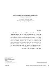
The neutronic analysis is carried out on the PACER blanket geometry described in [9]. Figure 1 shows the basic<br />
structure <strong>of</strong> the explosion chamber (a) and the coolant zone geometry (b) adapted from [9] <strong>for</strong> this work. <strong>Flibe</strong> (<strong>Li2BeF4</strong>)<br />
is selected as a coolant because <strong>of</strong> its highest neutronic per<strong>for</strong>mance and best wall protection [9]. All steel structures<br />
such as pipelines and liners are made <strong>of</strong> SS-316, which is compatible with the flibe. A realistic approach considered <strong>for</strong><br />
determination <strong>of</strong> the coolant zone corresponds to a coolant zone configuration that occurs in practice. In this approach,<br />
be<strong>for</strong>e the explosion processes, the flibe zone geometry shown in Figure 1 would occur approximately with injection <strong>of</strong><br />
cold flibe by means <strong>of</strong> the injection system on the top <strong>of</strong> the chamber, and the explosion process would carry on<br />
simultaneously with this coolant zone configuration. At the same time, the flibe injection would stop with the explosion<br />
process. The injection process is per<strong>for</strong>med by two sub-systems in the injection system. These sub-systems can provide a<br />
continuous flibe flow and a periodical flibe flow required <strong>for</strong> confinement <strong>of</strong> the explosion region by vertical and top–<br />
bottom sides, respectively. The periodical flow helps in the explosion void <strong>for</strong>mation (or the explosion region) in the<br />
coolant zone. Thereby, the coolant zone geometry is a liquid cylindrical <strong>for</strong>m surrounding the explosion region in its<br />
30 The Arabian Journal <strong>for</strong> Science and Engineering, Volume 29, Number 1A. January 2004
cylindrical <strong>for</strong>m (void). There<strong>for</strong>e,<br />
the working coolant amount as a<br />
function <strong>of</strong> the coolant zone position<br />
(DR) and the coolant zone thickness<br />
(DRc) can be calculated easily from<br />
this geometry. In addition, the flibe<br />
zone geometry serves in realistic<br />
equilibrium temperature and pressure<br />
calculations, with coolant mass<br />
calculated by the geometry and<br />
neutronic calculations in onedimensional<br />
spherical geometry,<br />
because it resembles a spherical<br />
shell <strong>of</strong> DRc thickness. Large fluid<br />
thickness at the top and bottom <strong>of</strong><br />
the flibe zone would provide higher<br />
safety <strong>for</strong> reactor parts such as the<br />
injection and circulation systems<br />
placed on the top and bottom <strong>of</strong> the<br />
explosion chamber. In the calculations,<br />
reactions such as fission or<br />
chemical reactions <strong>of</strong> burned fusion<br />
fuel, and neutronic, chemical, and<br />
mechanical effects <strong>of</strong> these reactions<br />
on the fusion neutrons, the flibe and<br />
other parts are ignored. Thereby, an<br />
anisotropic fusion neutron source <strong>of</strong><br />
14.1 MeV is assumed as a point<br />
source in the center <strong>of</strong> the explosion<br />
region or at the explosion point. For<br />
simplicity, the neutronic calculations<br />
are per<strong>for</strong>med in one-dimensional<br />
spherical geometry. At first sight,<br />
the neutronic analysis in onedimensional<br />
geometry <strong>for</strong> the flibe<br />
zone geometry may be considered<br />
invalid. However, <strong>for</strong> a neutronic<br />
analysis, the calculation dimensions<br />
are affected highly by the material<br />
composition and the source neutron<br />
flux direction. Approximately,<br />
fusion neutrons released from the<br />
explosion scatters in the radial<br />
direction <strong>of</strong> the sphere surface. If the<br />
variation <strong>of</strong> the material<br />
composition along the θ and ϕ<br />
components <strong>of</strong> the spherical<br />
coordinate system is homogeneous,<br />
the one-dimensional analysis with r<br />
The heated<br />
liquid flibe<br />
outlet<br />
The flibe<br />
vapour outlet<br />
Fusion<br />
explosive<br />
assembly<br />
The cold<br />
flibe inlet<br />
DRc<br />
DR<br />
Sebahattin Ünalan and Selahaddin Orhan Akansu<br />
January 2004 The Arabian Journal <strong>for</strong> Science and Engineering, Volume 29, Number 1A. 31<br />
The explosion<br />
region (void)<br />
The<br />
pulverized<br />
flibe<br />
H<br />
2 DR<br />
<strong>Flibe</strong><br />
injection<br />
system<br />
H = 4 (DR+DRc)<br />
Fusion<br />
explosive<br />
Continuous<br />
flibe flow<br />
Periodical<br />
flibe flow<br />
SS-316<br />
layer<br />
Underground Rock <strong>Flibe</strong> Zone<br />
Figure 1. Cross-sectional view <strong>of</strong> the explosion chamber <strong>of</strong> the PACER (a) and the flibe<br />
zone geometry (b).<br />
(b)<br />
(a)
Sebahattin Ünalan and Selahaddin Orhan Akansu<br />
component would be equal to a three-dimensional analysis. There<strong>for</strong>e, a one-dimensional spherical geometry <strong>for</strong> this<br />
study provides enough sensitivity. At the first stage <strong>of</strong> the neutronic calculations, the best position <strong>for</strong> the coolant zone<br />
(DR from the explosion point) in the reactor chamber and the optimal coolant thickness (DRc) <strong>for</strong> each position in terms<br />
<strong>of</strong> higher energy absorption and enough tritium breeding with lower flibe amount are investigated. In the calculations,<br />
while the positions <strong>of</strong> the coolant zone are selected as DR = 50, 400, 700, and 1000 cm, the coolant zone thickness are<br />
varied between DRc = 0 – 425 cm. The explosion chamber radius is assumed as 4×DR <strong>for</strong> neutronic calculations.<br />
In addition, the calculations are repeated <strong>for</strong> different volume fractions <strong>of</strong> flibe and void to symbolize the pulverization<br />
process that will occur during the flibe injection in practice. The flibe expanding to larger volume creates an easier<br />
vaporization process because the vaporization surface is increased. That is, the vaporization capability <strong>of</strong> the flibe can be<br />
increased by expanding to a higher volume by means <strong>of</strong> the pulverized flibe. For that purpose, volume fractions are<br />
preferred as 100% flibe, 25% void +75% flibe, 50% void +50% flibe, and 75% void +25% flibe. After the neutronic<br />
calculations, the equilibrium pressure and temperature is calculated by calculation models derived at previous and<br />
present papers. For these calculations, while the chamber pressure is assumed as 1 atm (= 10 5 Pa) be<strong>for</strong>e the explosion<br />
process, the preferred flibe inlet temperatures are 823 K <strong>for</strong> heated liquid flibe and saturated flibe vapor production and<br />
1540 K (the saturation temperature <strong>of</strong> flibe at 10 5 Pa) <strong>for</strong> only superheated vapor production. Atomic densities <strong>of</strong><br />
materials are not given in this text as they have been presented in [9]. In addition, the heat transfer calculation, design<br />
calculations, and more advanced in<strong>for</strong>mation <strong>for</strong> other parts such as the separators, the coolant system, and the turbine<br />
island <strong>of</strong> the PACER are not given because this is beyond the scope <strong>of</strong> the paper. Especially, the heat transferring<br />
calculations and analyzing <strong>of</strong> turbine systems will not be required because they could be directly adapted from the<br />
turbine systems <strong>of</strong> pressured water reactors (PWR).<br />
3. NUMERICAL RESULTS<br />
3.1. Calculational Tools<br />
The neutronic calculations have been per<strong>for</strong>med on a PC with a Pentium III coprocessor at 500 Mhz by solving the<br />
Boltzman Transport Equation with the neutron transport code ANISN/PC [10] using the neutron transport and activity<br />
cross section data libraries MATXS10 [11] and CLAW-IV [12]. The neutron cross sections are averaged over 30 energy<br />
groups using the Bondarenko [13] flux approximation with a fusion, fission, 1/E and thermal weight function.<br />
The energy structure has 12, 9, and 9 neutron groups between 1.353 MeV and 17 MeV, 1.235 KeV and 1.353 MeV, and<br />
0.000139 eV and 1.235 KeV, respectively. The integration <strong>of</strong> the angular neutron flux has been done in the S16–P3<br />
approximation by using Gaussian quadrature sets. The numerical output <strong>of</strong> the ANISN calculations has been further<br />
processed using the auxiliary code ERDEMLI [14] to evaluate specific in<strong>for</strong>mation <strong>for</strong> this work.<br />
3.2. Tritium Breeding and Energy Absorption<br />
While the best flibe zone position in the reactor chamber and the optimal coolant thickness is determined, main<br />
parameters are selected as high absorption <strong>of</strong> fusion neutron energy released from repetitive explosions and enough<br />
tritium breeding. There<strong>for</strong>e, high fusion neutron absorption concludes lower radiation damage on the explosion chamber<br />
wall. Namely, many <strong>of</strong> the fusion neutrons should be absorbed by the flibe to decrease damage effects on the first wall<br />
material (SS-316), to breed tritium and to capture the fusion neutron energy. However, tritium breeding <strong>of</strong> a fusion<br />
reactor must be slightly higher than tritium consumption (Tritium Breeding Ratio: TBR > 1).<br />
Figures 2–5 show M (Fusion Energy Absorption Ratio = total energy in MeV released in the reactor / 14.1 MeV) and<br />
TBR versus DRc <strong>for</strong> DR and flibe percentages <strong>of</strong> 25%, 50%, 75%, and 100%. As seen in these figures, TBR and M values<br />
increase rapidly with increasing DRc values, then a saturation with TBR = 1.27 and M = 1.07 is reached at certain DRc<br />
values. That is, TBR and M behave asymptotically after a certain DRc value, although the flibe thickness increases.<br />
The DRc values providing the saturation point, which indicates the beginning point <strong>of</strong> the asymptotic behavior, are about<br />
350, 175, 125, and 100 cm <strong>for</strong> 25%, 50%, 75%, and 100%, respectively. In practice, the flibe thickness must be equal to<br />
the saturation values because <strong>of</strong> the economical considerations. However, if DRc at the saturation point cannot provide<br />
the coolant mass requirement <strong>of</strong> the PACER, the flibe thickness can be selected higher than the saturation point.<br />
In addition, Figures 2–5 show that the effect <strong>of</strong> the coolant zone position DR on TBR and M at the saturation point can be<br />
32 The Arabian Journal <strong>for</strong> Science and Engineering, Volume 29, Number 1A. January 2004
Sebahattin Ünalan and Selahaddin Orhan Akansu<br />
Figure 2. Variation <strong>of</strong> M and TBR versus <strong>Flibe</strong> Thickness (DR C) <strong>for</strong> 25 % <strong>Flibe</strong> case.<br />
January 2004 The Arabian Journal <strong>for</strong> Science and Engineering, Volume 29, Number 1A. 33
Sebahattin Ünalan and Selahaddin Orhan Akansu<br />
Figure 3. Variation <strong>of</strong> M and TBR versus <strong>Flibe</strong> Thickness (DR C) <strong>for</strong> 50 % <strong>Flibe</strong> case.<br />
34 The Arabian Journal <strong>for</strong> Science and Engineering, Volume 29, Number 1A. January 2004
Sebahattin Ünalan and Selahaddin Orhan Akansu<br />
Figure 4. Variation <strong>of</strong> M and TBR versus <strong>Flibe</strong> Thickness (DR C) <strong>for</strong> 75 % <strong>Flibe</strong> case.<br />
January 2004 The Arabian Journal <strong>for</strong> Science and Engineering, Volume 29, Number 1A. 35
Sebahattin Ünalan and Selahaddin Orhan Akansu<br />
Figure 5. Variation <strong>of</strong> M and TBR versus <strong>Flibe</strong> Thickness (DR C) <strong>for</strong> 100 % <strong>Flibe</strong> case.<br />
36 The Arabian Journal <strong>for</strong> Science and Engineering, Volume 29, Number 1A. January 2004
Sebahattin Ünalan and Selahaddin Orhan Akansu<br />
almost ignored. In other words, the saturation point is not affected by various flibe zone positions. However, this<br />
approach has to be supported with clearer calculations because clear saturation values may not be selected from these<br />
figures. For that purpose, DRc saturation points calculated by means <strong>of</strong> linear interpolation <strong>for</strong> M = 1.07 and TBR = 1.27<br />
from Figures 2–5 are shown in Table 1. Table 1 shows that the DRc saturation values from Figures 2–5 are almost the<br />
same <strong>for</strong> all DR values and flibe percentages. The difference between TBR values calculated <strong>for</strong> DR = 50 and 1000 cm<br />
are 48 cm (= 421.9 – 374.6) and 4 cm (= 101.4 – 96.7) with 25% flibe and 100% flibe percentages, respectively.<br />
However, the same approach cannot be claimed <strong>for</strong> flibe mass values to be determined with the saturation DRc and DR<br />
because volume <strong>of</strong> the flibe zone having the cylindrical geometry is fairly affected by radius.<br />
DR<br />
[cm]<br />
Saturation value <strong>of</strong><br />
DR c (cm) <strong>for</strong> 25% flibe<br />
Table 1. DR c Saturation Points Provided by TBR = 1.27 and M = 1.07.<br />
Saturation value <strong>of</strong><br />
DR c (cm) <strong>for</strong> 50% flibe<br />
Saturation value <strong>of</strong><br />
DR c (cm) <strong>for</strong> 75% flibe<br />
Saturation value <strong>of</strong><br />
DR c (cm) <strong>for</strong> 100% flibe<br />
TBR = 1.27 M = 1.07 TBR = 1.27 M = 1.07 TBR = 1.27 M = 1.07 TBR = 1.27 M = 1.07<br />
50 421.98 312.18 208.87 151.60 140.20 99.41 101.46 74.26<br />
400 391.17 282.69 193.91 140.72 127.69 94.76 97.79 71.89<br />
700 381.84 274.37 190.97 138.16 124.83 93.70 97.21 71.39<br />
1000 374.60 270.36 188.69 136.20 124.23 92.84 96.72 70.96<br />
At this point, determination <strong>of</strong> the flibe mass values<br />
providing the saturation point would be important. In<br />
this case, the flibe mass needed <strong>for</strong> the PACER chamber<br />
can be calculated as function <strong>of</strong> DR, DRc, and flibe<br />
density (ρ) from the flibe zone geometry in Figure 1(b)<br />
by means <strong>of</strong> following equation:<br />
m = 2πρ[2(DR + DRc) 3 – DR 3 ] . (1)<br />
Variation <strong>of</strong> the flibe mass calculated by Equation (1)<br />
<strong>for</strong> DRc saturation points versus flibe zone position DR<br />
is given in Figure 6. As expected, m values providing<br />
enough tritium breeding and energy absorption increased<br />
with increasing <strong>of</strong> DR. For high TBR and M values with<br />
lower flibe amount, the flibe zone must be as close to the<br />
explosion region as possible. Thus, a lower flibe mass<br />
serves to give a lower cost <strong>for</strong> electrical energy. That is,<br />
<strong>for</strong> the best flibe zone position, DR has to be selected at<br />
the lowest value allowed by the reactor operation<br />
conditions. According to Figure 6, the flibe masses<br />
required <strong>for</strong> saturation <strong>of</strong> TBR are slightly higher than<br />
the values required <strong>for</strong> M. In this case, if the saturation<br />
point with TBR were selected, the same point would also<br />
provide high enough M values. At this stage, it would be<br />
interesting if the required flibe mass with TBR = 1.27<br />
and M = 1.07 <strong>for</strong> the flibe zone position in the explosion<br />
chamber were known analytically, because the determination<br />
<strong>of</strong> equilibrium temperatures–pressures and vapor<br />
production as a function <strong>of</strong> this flibe mass, the explosion<br />
Figure 6. Variation <strong>of</strong> m values with TBR=1.27 and M=1.07 versus DR.<br />
January 2004 The Arabian Journal <strong>for</strong> Science and Engineering, Volume 29, Number 1A. 37
Sebahattin Ünalan and Selahaddin Orhan Akansu<br />
chamber volume, and any explosive<br />
yield would be important in terms <strong>of</strong><br />
reactor operation conditions and<br />
reactor safety. For a more practical<br />
approach, the shapes <strong>of</strong> the curves<br />
in Figure 6 can be analytically<br />
explained by a polynomial function<br />
following:<br />
DR = A + B.m + C.m 2 + D.m 3 . (2)<br />
In Equation (2), DR and m are in<br />
cm and tonnes, respectively. For A,<br />
B, C, and D coefficients requiring<br />
the calculation within an accuracy <strong>of</strong><br />
1% are given in Table 2.<br />
There<strong>for</strong>e, if the m requirement is<br />
known, DR and DRc can be<br />
calculated by Equations (1) and (2).<br />
3.3. The Equilibrium Pressure–Temperature and <strong>Flibe</strong> Vapor Production<br />
In this section, flibe vapor production possibility, equilibrium pressures and temperatures <strong>for</strong> the investigated cases<br />
will be calculated. The meaning <strong>of</strong> the equilibrium is that the high turbulence that occurred in the few seconds following<br />
the explosion process has finished. <strong>Flibe</strong> vapor production possibility, equilibrium pressure, and temperature are<br />
important in terms <strong>of</strong> mechanical considerations, operation conditions, and reactor safety. Operation pressure and<br />
temperature <strong>of</strong> the reactor have to be lower than the values given <strong>for</strong> metallic parts. After the explosion process, up to a<br />
later explosion, the pressure and temperature values <strong>of</strong> the flibe vapor in the chamber decrease continuously because <strong>of</strong><br />
the vapor transferred to the turbine system. For this reason, the outlet temperature must be regulated to a constant value.<br />
This operation also depends on the equilibrium pressure and temperature. In addition, the quality <strong>of</strong> the produced vapor<br />
(saturated vapor or superheated vapor) also would be important from the standpoint <strong>of</strong> the selection <strong>of</strong> a turbine system<br />
working with or without condensation. The equations needed <strong>for</strong> calculation <strong>of</strong> the equilibrium pressure (Pf) and<br />
equilibrium temperature (Tf) can be adapted from [6] as follows:<br />
where,<br />
T<br />
f<br />
E − mv<br />
( ∆h<br />
− RTv<br />
) − mC p ( Tv<br />
−Ti<br />
n)<br />
+ mv<br />
Cv<br />
Tv<br />
= (3)<br />
m C<br />
v<br />
v<br />
mv<br />
RTf<br />
Pf<br />
= , (4)<br />
V<br />
E : the explosive energy yield = 2.95×10 24 ×[n/shot] 17.6 [MeV/n] 1.602×10 –13 [J/MeV]×M<br />
mv : mass <strong>of</strong> the vaporized flibe (m ≥ mv)<br />
V : the chamber volume <strong>of</strong> the PACER reactor [m 3 ]<br />
∆h : latent heat <strong>of</strong> flibe vapor = 2079 J/g<br />
Tv : the saturated vapor temperature: [K]<br />
Tin : inlet temperature <strong>of</strong> flibe: [K]<br />
Cv : 1.88 J/g K<br />
Cp : 2.35 J/g K<br />
R : 0.47 J/g K.<br />
Table 2. Numerical Coefficients <strong>for</strong> Equation (2).<br />
The case A B C D<br />
25%-TBR –88.0968 0.22493 –2.24936.10 –5 8.32157.10 –10<br />
50%-TBR 0.7992 0.23279 –2.58172.10 –5 9.94182.10 –10<br />
75%-TBR 21.4882 0.22411 –2.40462.10 –5 8.33179.10 –10<br />
100%-TBR 32.7906 0.20319 –1.97084.10 –5 5.91985.10 –10<br />
25%-M –42.2288 0.32536 –4.80213.10 –5 2.64298.10 –09<br />
50%-M 19.1456 0.30891 –4.58881.10 –5 2.24291.10 –09<br />
75%-M 33.1814 0.27705 –3.66058.10 –5 1.49366.10 –09<br />
100%-M 38.5927 0.24771 –2.88471.10 –5 9.98872.10 –10<br />
38 The Arabian Journal <strong>for</strong> Science and Engineering, Volume 29, Number 1A. January 2004
Sebahattin Ünalan and Selahaddin Orhan Akansu<br />
Pf and Tf can be calculated by means <strong>of</strong> Equations (3) and (4). However, the saturation temperature Tv, that depends on<br />
the saturation pressure (Pv), must be defined. According to [6], Pv in Pascal and Tv in K can be found by:<br />
v<br />
9.<br />
407−10054<br />
/ T<br />
v<br />
P = 133(<br />
10<br />
)<br />
(5)<br />
mv<br />
RTv<br />
Pv<br />
= . (6)<br />
V<br />
Considering that Equations (3–6) are closed functions, it is clear that their solutions can be found by means <strong>of</strong><br />
iteration methods. These calculations <strong>for</strong> liquid flibe and flibe vapor (assuming ideal gas behavior) are per<strong>for</strong>med in light<br />
<strong>of</strong> following scenario:<br />
• Liquid flibe having temperature <strong>of</strong> Tin will heat up to Tv at the constant pressure <strong>of</strong> 1 atm. If E values are lower than<br />
[mCp (Tv–Tin)], only the liquid flibe heated up to Tv will be obtained.<br />
• If E values are higher than [mCp (Tv–Tin)], heat the liquid flibe up to Tv and vaporize the liquid <strong>of</strong> mv at Pv pressure<br />
and constant volume. If E values are lower than [mCp(Tv–Tin) +m(∆h –RTv)], the saturated flibe vapor <strong>of</strong> mv and<br />
the heated liquid flibe <strong>of</strong> m–mv at Pv pressure and Tv temperature will be obtained.<br />
• If E values are higher than [mCp (Tv–Tin) + m(∆h – RTv)], superheat up to Tf at constant volume and calculate Pf.<br />
In this case, the superheated flibe vapor <strong>of</strong> m = mv at Pf pressure and Tf temperature will be obtained.<br />
If all the liquid flibe mass converted to the vapor phase, the mv value would be equal to the m value. In this case,<br />
superheated vapor production would be possible. If Tf = kTv and EV = E/V, Equations (2–5) can be converted as follows:<br />
133(<br />
10<br />
EV =<br />
rT<br />
9.<br />
407−10054/<br />
Tv<br />
v<br />
)<br />
[ ∆h<br />
+ C kT<br />
− C T ]<br />
v<br />
v<br />
p in<br />
, (7)<br />
where k indicates the produced vapor quality. If k = 1, the flibe vapor is at the saturation condition. For the superheated<br />
vapor production, k has to be higher than unity (k > 1). EV is the ratio <strong>of</strong> the fusion explosion yield (E) to the explosion<br />
chamber volume (V). The EV value at any k and Tv or Tf (= kTv) can be calculated from Equation (6). However, it would<br />
be more useful to show Equation (6) in a Figure because it cannot be easily solved. There<strong>for</strong>e, Tf values found <strong>for</strong><br />
various k values as a function <strong>of</strong> EV (in MJ/m 3 ) can be shown in Figure 7 <strong>for</strong> Tin = 823 K and Tin = 1540 K, respectively.<br />
On the other hand, if m = mv <strong>for</strong> full vaporization and Cp = R+Cv, the reactor volume and flibe mass required <strong>for</strong> any<br />
explosion yield E can be calculated from:<br />
E<br />
V = (8)<br />
EV<br />
E<br />
m = . (9)<br />
C T + ∆h<br />
− C T<br />
v<br />
f<br />
p in<br />
In addition, the equilibrium pressure Pf <strong>for</strong> m and V are found from Equation (4). Consequently, the equilibrium<br />
pressure (Pf), equilibrium temperature (Tf), reactor volume (V) and flibe mass (m) required <strong>for</strong> the desired explosion<br />
yield (E) value can be determined by Figures 6 and 7 and Equations (4), (8), and (9).<br />
For example, <strong>for</strong> Tin = 823 K, Tf = 2250 K, and k = 1.2 [1.2 means Tv = 1875 K and a temperature decrease <strong>of</strong> 375 K<br />
(≈2250–1875 K) at the turbine system], EV is found as 7 MJ/m 3 from Figure 7. There<strong>for</strong>e, <strong>for</strong> explosion yield <strong>of</strong><br />
8.37×10 12 J (= 2 kt equivalent TNT), m and V can be calculated as 1913 tonnes from Equation (8) and 1195714 m 3<br />
(corresponding to a spherical geometry having a radius <strong>of</strong> 65 m) from Equation (8). In addition, the equilibrium pressure<br />
is found as 17×10 5 Pa from Equation (4). At the given conditions, the critical coolant position DR with the saturation<br />
point <strong>of</strong> TBR should be about 265 cm from Equation (2) <strong>for</strong> m = 1913 tonnes and 25% flibe. In this case, the flibe zone<br />
thickness would be equal to DRc = 415 cm from Equation (1). However, an m value <strong>of</strong> 1913 tonnes also can be provided<br />
January 2004 The Arabian Journal <strong>for</strong> Science and Engineering, Volume 29, Number 1A. 39
Sebahattin Ünalan and Selahaddin Orhan Akansu<br />
Tin=823 o K<br />
Tin = 1540 K Tin = 823 K<br />
k=2.4<br />
k=2.5<br />
k=2.5<br />
k=2.4<br />
Tin=1540 o K<br />
k=2.3<br />
k=2.3<br />
k=2.2<br />
k=2.2<br />
k=2.1<br />
k=2.0<br />
k=1.9<br />
k=1.8<br />
k=1.7<br />
k=1.6<br />
k=1.5<br />
k=2.1<br />
k=2.0<br />
k=1.9<br />
k=1.8<br />
k=1.7<br />
k=1.6<br />
k=1.5<br />
Tf (K)<br />
40 The Arabian Journal <strong>for</strong> Science and Engineering, Volume 29, Number 1A. January 2004<br />
k=1.4<br />
Figure 7. Variation <strong>of</strong> T f versus EV (the explosive yield/the chamber volume) in various k values <strong>for</strong> T in=1540 K and 823 K.<br />
k=1.4<br />
k=1.3<br />
k=1.3<br />
k=1.2<br />
k=1.2<br />
k=1.1<br />
k=1.1<br />
k=1.0<br />
k=1.0<br />
0 5 10 15 20 25 30 35 40 45 50 55 60<br />
0 5 10 15 20 25 30 35 40 45 50 55 60<br />
EV (MJ/m 3 EV (MJ/m ) 3 )<br />
EV (MJ/m 3 )<br />
EV (MJ/m 3 )
Sebahattin Ünalan and Selahaddin Orhan Akansu<br />
by DR < 265 cm and DRc > 415 cm. At this point, while the case given lowest flibe mass can be preferred, it must be<br />
attended that distribution <strong>of</strong> energy absorption across the flibe zone spatial is flatted. For the flatted energy absorption in<br />
the flibe zone after the explosion process, the temperature difference between inner-side and outer-side <strong>of</strong> the flibe zone<br />
should be the lowest value. The very much temperature difference can cause instantaneous fluid explosion and unsteady<br />
behavior, which may be hazard <strong>for</strong> the reactor safety. Thereby, the DR with the saturation point will be enough. For inlet<br />
temperature <strong>of</strong> Tin = 1540 K, the same values are about 15 atm, 5 MJ/m 3 , 3100 tonnes, 1674000 m 3 , and DR ≈ 550 cm,<br />
respectively. These values show that high inlet temperature cause high chamber volume and flibe mass.<br />
Consequently, in order to design a PACER, the main parameters such as the flibe zone position, the flibe thickness, the<br />
explosion chamber volume, and flibe mass <strong>for</strong> given explosive and flibe inlet conditions can be determined by the above<br />
figures and equations. It can be decided whether a design should have a double loop with a heat exchanger, as <strong>for</strong> PWRs,<br />
with the heated liquid flibe, or one loop, as <strong>for</strong> BWRs, with the saturated flibe vapor.<br />
4. CONCLUSIONS AND RECOMMENDATIONS<br />
In this study, the vapor production possibility, the equilibrium pressure, and temperature occurring in the explosion<br />
chamber <strong>of</strong> a PACER producing electrical energy from fusion explosions repeated in a certain repetition period <strong>for</strong><br />
different coolant zone positions (DR) and coolant zone thickness (DRc), with enough tritium breeding and more fusion<br />
energy absorption, are analyzed. <strong>Flibe</strong> (<strong>Li2BeF4</strong>) with various volume fractions is preferred as a coolant. The analysis<br />
expands to two inlet temperatures (Tin) <strong>of</strong> 823 K and 1540 K. The main conclusions are as follows:<br />
1. For tritium breeding and energy absorption at a certain flibe mass (or certain flibe thickness), saturation is reached.<br />
TBR and M values calculated at the saturation point are equal to 1.27 and 1.07, respectively. The saturation mass <strong>of</strong><br />
the flibe increases with increasing DR. For the same explosive yield, low DR indicates high flibe temperature.<br />
However, <strong>for</strong> the sake <strong>of</strong> reactor safety, a high enough working temperature can be provided by higher flibe mass<br />
or high DR value. To decrease the flibe mass required <strong>for</strong> sufficient tritium breeding (TBR > 1) and more fusion<br />
neutron energy absorption (M = 1), DR must be as low as possible.<br />
2. As an example, <strong>for</strong> a working temperature <strong>of</strong> 2250 K with the explosive yield <strong>of</strong> 8.37×10 12 J (2 kt equivalent TNT)<br />
and Tin = 823 K, a flibe mass <strong>of</strong> 1913 tonnes, an explosion chamber volume <strong>of</strong> 1195714 m 3 , and DR = 265 cm are<br />
enough. For Tin = 1540 K, the flibe mass, the chamber volume, and DR values are about 3100 tonnes, 1 674 000 m 3 ,<br />
and 550 cm. There<strong>for</strong>e, high flibe inlet temperature requires higher flibe mass and chamber volume.<br />
The following recommendations can be given <strong>for</strong> future studies:<br />
1. Effects <strong>of</strong> chemical or fission mechanisms required <strong>for</strong> initiation <strong>of</strong> fusion explosions on neutronic per<strong>for</strong>mance,<br />
flibe, and other reactor parts must be determined.<br />
2. Chemical and mechanical damage caused by high impact velocity on the SS-316 liner have to be investigated <strong>for</strong><br />
better selection <strong>of</strong> flibe zone placement in the explosion chamber.<br />
3. The effects <strong>of</strong> the shock waves from the explosions on the reactor plant and the integrity <strong>of</strong> the reactor vessel must<br />
be investigated both theoretically and experimentally.<br />
REFERENCES<br />
[1] E. Teller, W. Talley, and G. Higgins, Constructive Uses <strong>of</strong> Nuclear Explosives. New York: McGraw-Hill Book Company, 1968.<br />
[2] H.W. Hubbard et al., Project PACER Final Report. RDA-TR-4100-003, R&D Associates, 1974.<br />
[3] R.P. Hammond et al., “Practical Fusion Power”, Mech. Egn., 104 (1982), p. 34.<br />
[4] W. Seifritz, “PACER: A Grand Design <strong>for</strong> Fusion Power”, Fusion, 4 (1980), p. 22.<br />
[5] R.W. Moir, “PACER Revisited”, Fusion Technology, 15 (1989), p. 1114.<br />
[6] C.J. Call and R.W. Moir, “A Novel Fusion Power Concept Based on Molten-Salt Technology: PACER Revisited”, Nuclear<br />
Science and Engineering, 104 (1990), p. 364.<br />
[7] A. Szöke and R.W. Moir, “A Practical Route to Fusion Power”, Techno. Rev., 94 (1991), p. 20.<br />
January 2004 The Arabian Journal <strong>for</strong> Science and Engineering, Volume 29, Number 1A. 41
Sebahattin Ünalan and Selahaddin Orhan Akansu<br />
[8] A. Szöke and R.W. Moir, “A Realistic, Gradual and Economical Approach to Fusion Power”, Fusion Technology, 20 (1991),<br />
p. 1012.<br />
[9] S. Şahin, R.W. Moir, and S. Ünalan, “Neutronic Investigation <strong>of</strong> A Power Plant Using Peaceful Nuclear Explosives”, Fusion<br />
Technology, 26 (1994), p. 1311.<br />
[10] W.W. Engle, Jr., ANISN, A One-Dimensional Discrete Ordinates Transport Code with Anisotropic Scattering. K1693,<br />
Oak Ridge National Laboratory, 1970.<br />
[11] R.E. MacFarlane, MATXS10, 30-Neutron, 12-Group Photon Cross Sections from ENDF/B-IV with TRANSX-2. Los Alamos<br />
National Laboratory, 1994.<br />
[12] T.A. Al-Kusayer, S. Şahin, and A. Drira, “CLAW-IV, Coupled 30 Neutrons, 12 Gamma Ray Group Cross Sections with<br />
Retrieval Programs <strong>for</strong> Radiation Transport Calculations”, Radiation Shielding In<strong>for</strong>mation Center, RSIC Newsletter, Oak Ridge<br />
National Laboratory, May 1988, p. 4.<br />
[13] Group Constants <strong>for</strong> Nuclear <strong>Reactor</strong> Calculations. ed. I.I. Bondarenko. New York: Consultants Bureau, 1964.<br />
[14] S. Şahin, H. Yapici, and S. Ünalan, ERDEMLI, A Computer Program to Process ANISN Output Data. Gazi University, Ankara,<br />
Turkey, 1991.<br />
Paper Received 6 November 2000; Revised 8 December 2001; Accepted 12 February 2003.<br />
42 The Arabian Journal <strong>for</strong> Science and Engineering, Volume 29, Number 1A. January 2004