Dipl. Ing. Matthias Mayerhofer Technische Universität München ...
Dipl. Ing. Matthias Mayerhofer Technische Universität München ...
Dipl. Ing. Matthias Mayerhofer Technische Universität München ...

Create successful ePaper yourself
Turn your PDF publications into a flip-book with our unique Google optimized e-Paper software.
Experiments 45<br />
Table 3: Biomass feedstock elemental and proximate analysis in [wt %]<br />
C waf H waf N waf S waf O waf<br />
49,9 6,8 0,1 0,1 43,2<br />
Water Ash db Volatile db Fix C db<br />
4,8 0,1 85,6 14,3<br />
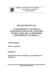
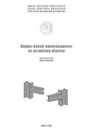
Biomass 2 kg/h<br />
Fluidised<br />
Bed<br />
800°C<br />
Steam 2kg/h<br />
Heatpipes<br />
Cyclone<br />
Particle<br />
Filter<br />
GC SPA<br />
Catalytic Test Rig Product Gas<br />
GC SPA<br />
Figure 18: Overview of the facility<br />
1<br />
2<br />
3<br />
Thermocouples<br />
Combustion chamber<br />
Catalytic Test Rig:<br />
The catalyst reactor can be seen in Figure 19. The catalyst is placed in a tube (inner diameter 2-5<br />
cm) which contains a grid at the bottom and the top to ensure that the fine particles of the catalyst<br />
are not swept away by the gas during the experiment. The dimensions of the test rig can be seen in<br />
detail in Table 4.<br />
Table 4: Dimensional details of the bed<br />
Height of the test rig Height of the tube Height of the bed<br />
400 mm 220 mm 75 mm<br />
The heating inside the catalyst bed is monitored by three thermocouples placed at the bottom, the<br />
middle and the top of the bed. Hence, an overview of the temperatures inside the bed is achieved.<br />
The measurements indicated that the temperature was uniform inside the bed during the whole<br />
experiment.