Download as a PDF
Download as a PDF
Download as a PDF

Create successful ePaper yourself
Turn your PDF publications into a flip-book with our unique Google optimized e-Paper software.
Analysis and initial synthesis of a novel linear<br />
actuator with active magnetic suspension<br />
Anton V. Lebedev, Elena A. Lomonova, Peter G. van<br />
Leuven, Joris Steinberg<br />
Electrical Engineering Department<br />
Eindhoven University of Technology<br />
Eindhoven, The Netherlands<br />
a.lebedev@tue.nl<br />
Abstract—In this paper attention is given to the initial design and<br />
experimental verification of the novel IU-shaped<br />
electromechanical actuator <strong>as</strong> a part of six degrees of freedom (6-<br />
DoF) contactless sliding system. Such a synergetic system is<br />
reached by integration of electromagnetic and mechanical<br />
structures of magnetic bearing and linear electromechanical<br />
actuator. Initially the performance of the electromagnetic module<br />
is examined. An analytical investigation of decoupled forces,<br />
originated from permanent magnets and suspension coils <strong>as</strong><br />
functions of rotor position and current values in the control coils,<br />
is performed. Numerical results (the FEM models - Maxwell 3D<br />
Ansoft Co.) are validated by static me<strong>as</strong>urements. Initial<br />
geometry is modified to demonstrate the improvement of the<br />
actuator performance.<br />
Keywords–actuators, finite element methods; magnetic forces;<br />
magnetic levitation; magnetostatics; soft magnetic materials<br />
I. INTRODUCTION<br />
An IU-shaped electromechanical actuator is a part of a new<br />
linear slider system (Fig. 1) for six degrees of freedom (6 DoF)<br />
suspension and propulsion described in [1, 2]. This system is<br />
tailored for optical discs m<strong>as</strong>tering applications and should<br />
provide the movement along one long stroke sliding direction<br />
while being stabilized in other directions.<br />
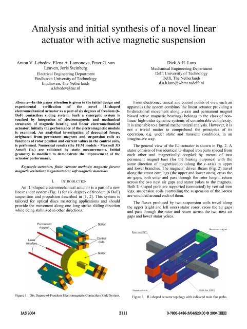
Figure 1. Six Degree-of-Freedom Electromagnetic Contactless Slide System.<br />
Dick A.H. Laro<br />
Mechanical Engineering Department<br />
Delft University of Technology<br />
Delft, The Netherlands<br />
d.a.h.laro@wbmt.tudelft.nl<br />
From electromechanical and control points of view such an<br />
apparatus (the system combines the linear actuator providing a<br />
bi-directional movement along x-axis and permanent magnet<br />
bi<strong>as</strong>ed active magnetic bearings) belongs to the cl<strong>as</strong>s of nonlinear<br />
high-order dynamic systems of considerable complexity.<br />
It is amenable to a formal mathematical analysis. However, it is<br />
not a trivial matter to comprehend the principles of its<br />
operation, e.g. under static and transient conditions, in an<br />
imaginative way.<br />
The general view of the IU–actuator is shown in Fig. 2. A<br />
stator consists of two identical U-shaped iron parts spaced from<br />
each other and magnetically coupled by means of two<br />
permanent magnet bars (for the bi<strong>as</strong>ing purposes) with the<br />
same direction of magnetization (along the y–axis) in upper<br />
and lower branches. The magnets’ driven fluxes (Fig. 2) travel<br />
along the stator core legs (the upper and lower ones), cross the<br />
air gaps, both enter and p<strong>as</strong>s through the rotor length, return<br />
across the two next air gaps and stator yokes to the magnets.<br />
Both U-shaped parts are supported (connected) by vertical iron<br />
legs, suspension coils controlling the suspension of the I-rotor<br />
are wounded around each of them.<br />
The fluxes produced by two suspension coils travel along<br />
the upper (right and left ones) stator cores, cross the air gaps<br />
and p<strong>as</strong>s through the rotor and return across the two next air<br />
gaps and lower stator yokes.<br />
Figure 2. IU-shaped actuator topology with indicated main flux paths.<br />
IAS 2004 2111<br />
0-7803-8486-5/04/$20.00 © 2004 IEEE
Four propulsion coils (Fig. 3) are placed consequently<br />
around each long iron bar (two upper and two lower stator<br />
bars). A rotor (mover) is inserted in the clearance between<br />
halves of the U-shaped stator parts. The rotor includes no field<br />
sources. All resulting forces acting on the rotor are reluctance<br />
forces, caused by the permanent magnets and the suspension<br />
coils, and the Lorenz forces caused by the propulsion coils.<br />
Usually, in magnetically levitated systems the role of the<br />
bi<strong>as</strong>ing is to improve the linearity and dynamic performance. In<br />
this paper practical application of a bi<strong>as</strong>ing scheme, b<strong>as</strong>ed on<br />
incorporating permanent magnets (PMs) into the magnetic<br />
structure, is reported. The primary advantage of this scheme is<br />
a reduction in electrical power consumption. The magnetic<br />
flux, created by the upper permanent magnets (Fig. 3 green<br />
arrows) crosses the two upper air gaps that causes reluctance<br />
forces (Fz-upper-right, Fz-upper-left) in both air gaps between two<br />
upper stator bars and rotor (mover). The magnetic flux from<br />
the lower PMs causes reluctance forces (Fz-lower-right, Fz-lower-left)<br />
in both air gaps between two lower stator bars and rotor<br />
(mover). These magnetic fluxes are called bi<strong>as</strong> fluxes.<br />
To be able to control the reluctance forces on the mover<br />
(rotor), two additional coils are placed at the ends of stator legs<br />
and the extra (control) forces are generated (Fig. 3 red arrows).<br />
These control forces are dependent on the applied current and<br />
rotor position. The total suspension force acting on the rotor is<br />
the sum of the reluctance forces and the control forces. It h<strong>as</strong> a<br />
small x-component in the direction of motion (propulsion) and<br />
a significant suspension force (z-component) along a vertical<br />
axis.<br />
Horizontal position of the rotor bar is controlled by the<br />
propulsion coils. Propulsion principle is b<strong>as</strong>ed on the<br />
interaction between the magnetic fluxes crossing the air gaps<br />
and the currents in the propulsion coils that cause the Lorenz<br />
forces acting on the rotor along the x-direction (Fig. 3 blue<br />
arrows). Obviously, the electromagnetic field generated by the<br />
propulsion coils distorts the distribution of the flux density in<br />
the stator bars and generates additional reluctance forces.<br />
The y-component of the forces is neglected, <strong>as</strong> it remains<br />
very small with respect to the other x- and z- force components.<br />
Figure 3. Forces acting on the rotor bar (colors of the arrows correspond to<br />
the colors of the electromagnetic field sources–PMs and coils.<br />
As it follows from the Fig. 5 the field distribution possesses<br />
a three-dimensional nature. Besides, the large air gaps cause<br />
significant values of leakage fluxes. Thus, the analysis of the<br />
actuator is becoming very complex.<br />
II. PRELIMINARY ANALYSIS<br />
To prove the appropriateness of the proposed IU-shaped<br />
module for being used in the above described system, the<br />
magnetostatic analysis is performed. To simplify the study it is<br />
divided into several stages. The first step of investigation is to<br />
estimate the behavior of the actuator with the permanent<br />
magnets only. The profiles of the force dependencies versus the<br />
z- and x-displacement of the rotor are obtained, and paths and<br />
values of the leakage fluxes are estimated. The same<br />
procedure, carried out for the IU-shaped module with PMs and<br />
suspension coils, forms the second step. The third, more<br />
complicated, stage is to study the actuators behavior with all<br />
three field sources. The two components of the total force<br />
acting on the rotor bar, namely Fx and Fz, are used <strong>as</strong> design<br />
functions,. They are dependent on the actuator geometry,<br />
materials, current values in the coils and position of the rotor in<br />
the xz–plane. During the analysis it w<strong>as</strong> <strong>as</strong>sumed that torques<br />
around the x– and y–axes are eliminated by the constructive<br />
arrangement of the total 6 DoF system and torque around the<br />
z–axis can be controlled by the propulsion coils.<br />
A. Analytical approach<br />
For the simplest c<strong>as</strong>e of the IU–shaped actuator structure<br />
with only permanent magnets several different approaches are<br />
used for the force computation. First of all, a coarse analytical<br />
model is created utilizing the virtual displacement method. It<br />
allows a decoupled estimation of vertical suspension force Fz<br />
resulting from permanent magnets and suspension coils. The<br />
calculation of electromagnetic forces by direct differentiation<br />
of the magnetic energy or coenergy is straightforward, and<br />
perfectly rigorous.<br />
Generally, the force fq due to the presence of permanent<br />
magnets acting on a rotor bar in an arbitrary q-direction is<br />
equal to a derivative of coenergy Wce with respect to q while<br />
the flux linkage ψ is constant.<br />
∂Wce f q =−<br />
∂q ∂ 1 2<br />
Ψ = const =− ( ⋅ Ф R m ) Ψ = const =<br />
∂q<br />
2<br />
⎡1 =− ⎢ Ф<br />
⎣2 ∂R ∂q + ФR<br />
∂Ф<br />
⎤<br />
∂q ⎥<br />
⎦<br />
1<br />
=− Ф<br />
2<br />
∂R<br />
∂q<br />
2 m 2 m<br />
m Ψ = const Ψ = const<br />
where Ф is a flux created by permanent magnet and Rm is total<br />
reluctance of magnetic circuit. The force fq due to the presence<br />
of control coils acting on a rotor bar in q-direction is<br />
∂Wce f q =−<br />
∂q ∂ 1 2<br />
Ψ = const =− ( ⋅ F Λ m ) Ψ = const =<br />
∂q<br />
2<br />
⎡1 =− ⎢ F<br />
⎣2 ∂Λ ∂q + FΛ<br />
∂F⎤<br />
∂q ⎥<br />
⎦<br />
1<br />
=− F<br />
2<br />
∂Λ<br />
∂q<br />
2 m 2 m<br />
m Ψ = const Ψ = const<br />
IAS 2004 2112<br />
0-7803-8486-5/04/$20.00 © 2004 IEEE<br />
(1)<br />
(2)
where F is magnetomotive force of the coil and Λ is a total<br />
m<br />
permeance of magnetic circuit.<br />
a) b)<br />
Figure 4. Equivalent magnetic circuits for decoupled force calculations: a)<br />
reluctance elements, b) permeance elements.<br />
To determine the above mentioned total reluctance and<br />
permeance the corresponding simple equivalent magnetic<br />
circuits (Fig. 4 a, b) have being built taking into account the<br />
leakage fluxes and fringing effects b<strong>as</strong>ed on FEM calculation<br />
results and [4]. An equivalent scheme represented in Fig. 4 a) is<br />
related to the flux originated from permanent magnet source<br />
and is <strong>as</strong>sociated with two horizontal circuits of the IU-actuator<br />
(green lines in Fig. 2). Fig. 4 b) represents the flux from<br />
another source (suspension coil) and is <strong>as</strong>sociated with vertical<br />
plane perpendicular to the rotor bar (red lines in Fig. 2).<br />
The input reluctance and permeance of the corresponding<br />
equivalent circuits are<br />
Λ<br />
m<br />
R<br />
m<br />
2 ⋅ Rδ<br />
⋅ R<br />
=<br />
2 ⋅ R + R<br />
( Λ<br />
=<br />
Λ<br />
δ1<br />
δ 1<br />
δ<br />
+ Λ<br />
+ Λ<br />
δ 2<br />
δ 2<br />
leak<br />
leak<br />
) ⋅ Λ<br />
+ Λ<br />
, (3)<br />
where index “leak” means a leakage through the permitted<br />
constructive clearance between stator bars, index δ is the air<br />
gap and indexes δ1 and δ2 are the upper and lower air gaps<br />
respectively. After substitution of the corresponding values of<br />
reluctances and permeances into (3) and (4) and further<br />
simplifications, the total reluctance and total permeance are<br />
derived <strong>as</strong> functions of the z-position (Rm(z) and Λm(z)).<br />
The method for predicting the force distribution in IUshaped<br />
actuator and its governing equations are implemented in<br />
a form of a rapid computational tool in Mathcad, and<br />
simulation results are compared with FEM calculation results.<br />
However, this simple decoupled approach does not show<br />
the interaction between the magnetic fields of the PMs and<br />
suspension coils and can not predict in a proper way the<br />
behavior of the actuator, for example, in c<strong>as</strong>e of partial<br />
saturation of the rotor or the stator bars. That w<strong>as</strong> demonstrated<br />
by a more accurate FEM analysis and me<strong>as</strong>urements on the test<br />
set-ups. A new analytical model taking into account the partial<br />
saturation of the stator and the rotor bars, leakage fluxes and<br />
leak<br />
leak<br />
(4)<br />
cross–coupling effects between the suspension and the<br />
propulsion directions is currently under development [7, 9].<br />
Figure 5. Field distribution in IU-shaped actuator with PMs and suspension<br />
coils introduced.<br />
B. FEM investigation<br />
Complicated nature (Fig. 5) of the field distribution caused<br />
by the 3D geometry and significant influence of the leakage<br />
fluxes make the analytical analysis of the actuator very<br />
difficult. The FEM magnetostatic calculations (Maxwell 3D<br />
Ansoft Co. [3]) are used for more accurate estimation of the<br />
field quantities and forces originated from the permanent<br />
magnets and the coils for the varied positions of the rotor along<br />
the z- and x-axes, [10].<br />
In Maxwell 3D Ansoft Co. the 3D FEM modification of the<br />
virtual work method (Coulomb virtual work method; [8]) is<br />
implemented. This method allows making a virtual<br />
displacement analytically. Considering the vector magnetic<br />
potential ( A ) formulation of a 3D problem in Cartesian<br />
coordinates, the coenergy is a function of A , J (current<br />
density) and coordinates x, y, z. Considering a virtual<br />
displacement in an arbitrary q–direction (x, y or z) and holding<br />
J constant<br />
∂W 'e ⎛∂W'e ∂A⎞<br />
fq= ( A, q)<br />
= ⋅ +<br />
∂q ⎜<br />
A q<br />
⎟<br />
⎝ ∂ ∂ ⎠Avarying<br />
⎛∂W'e⎞ + ⎜<br />
∂q<br />
⎟<br />
⎝ ⎠<br />
A constant<br />
It can be observed that the finite element method finds the<br />
distribution of A which makes<br />
f<br />
q<br />
∂W<br />
'<br />
∂A<br />
⎛∂W'e⎞ = ⎜<br />
∂q<br />
⎟<br />
⎝ ⎠<br />
e<br />
= 0<br />
A constant<br />
. Thus,<br />
IAS 2004 2113<br />
0-7803-8486-5/04/$20.00 © 2004 IEEE<br />
(5)<br />
(6)
which can be obtained from a straightforward initial position<br />
field solution.<br />
Force (N)<br />
150<br />
100<br />
50<br />
0<br />
-50<br />
-100<br />
-150<br />
-0.8 -0.6 -0.4 -0.2 0 0.2 0.4 0.6 0.8<br />
z-displacement (mm)<br />
Figure 6. Analytical (– –) and numerical (—) force profiles (originated by<br />
permanent magnets) dependent on the z-axis rotor position.<br />
Force (N)<br />
20<br />
15<br />
10<br />
5<br />
0<br />
-5<br />
-10<br />
-15<br />
-20<br />
-0.8 -0.6 -0.4 -0.2 0 0.2 0.4 0.6 0.8<br />
z-displacement (mm)<br />
Figure 7. Analytical (– –) and numerical (—) force profiles (originated by<br />
suspension coils) dependent on the z-axis rotor position.<br />
In Fig. 6 and Fig. 7 the comparison of the results obtained<br />
by analytical and numerical (FEM) calculations of the<br />
decoupled suspension forces created by the permanent magnets<br />
and the suspension coils is shown respectively.<br />
During the FEM simulations the isotropic properties of the<br />
stator and the rotor bars material are considered (that is valid in<br />
c<strong>as</strong>e of the use, for example, of the SMC – Somaloy TM 500,<br />
Höganäs AB; [6]). The calculations are carried out for a few<br />
permanent magnets configurations <strong>as</strong> well <strong>as</strong> for the different<br />
materials and positions of the rotor bar. The main sizes of the<br />
models, which are used for analytical, numerical and<br />
experimental studies, are presented in Table 1.<br />
TABLE I. INITIAL GEOMETRY PARAMETERS OF THE IU-MODULE<br />
4 stator bars 20 x 20 x 200 mm 3 (each)<br />
1 rotor bar 20 x 20 x 250 mm 3<br />
2 suspension coil cores 20 x 20 x 22.2 mm 3 (each)<br />
Air gap height 1.1 mm<br />
Permanent magnets 63 x 36 x 10 mm 3<br />
The analytical expression for estimation of the z-force<br />
component <strong>as</strong>sumes the flux, flowing through the working air<br />
gap, is perpendicular to the surfaces of the stator and rotor bars.<br />
Furthermore, the flux lines are <strong>as</strong>sumed to be straight, while<br />
the permeability of the magnetic material is equal to infinity<br />
(µSMC=∞) and the leakage flux value is constant. Only the<br />
reluctances or permeances of the working air gap are<br />
dependent on the z-position. FEM analysis shows that the main<br />
part of the flux does p<strong>as</strong>s the working air gap in the above<br />
mentioned way (Fig. 8, Fig. 9). Therefore, a sufficient accuracy<br />
of the analytical z-force expressions is obtained for both the<br />
force originated from the permanent magnets and the force<br />
from the suspension coils (Fig. 6, Fig. 7).<br />
Figure 8. 2D field distribution in U-shaped part of the actuator originated<br />
from the suspension coil.<br />
Figure 9. Zoomed 2D field distribution in the working air gap.<br />
According to the virtual displacement principle the x-force<br />
can be determined analytically by (1) <strong>as</strong> well. The x-component<br />
of the force acting on the rotor is generated by the magnetic<br />
IAS 2004 2114<br />
0-7803-8486-5/04/$20.00 © 2004 IEEE
flux p<strong>as</strong>sing through the side face of the rotor (red d<strong>as</strong>hed line<br />
in Fig. 9) and is actually a part of the leakage flux flowing<br />
through the constructive clearance between the two upper or<br />
the two lower stator bars. Additional permeances should be<br />
included in the equivalent circuit representing this part of the<br />
flux. However, the part of the magnetic flux entering the rotor<br />
in x–direction is significantly smaller than the one in z–<br />
direction and even than the leakage flux. Besides, the shape of<br />
the air gap through which that part of the flux is p<strong>as</strong>sing is nontrivial<br />
due to the fringing effect. This inhibits the creation of an<br />
equivalent circuit for the analytical determination of the x–<br />
force. Several topologies of equivalent circuits being<br />
investigated are proven to be of insufficient accuracy. This<br />
makes the FEM models very important on the initial stage of<br />
the development.<br />
III. SYNTHESIS OF THE GEOMETRY<br />
This subsection describes the peculiar design choices<br />
concerning the UI-module geometry leading to an improved<br />
electromagnetic performance.<br />
A. Specifications<br />
Starting point in the design is determining the set of<br />
specifications. The following specifications are required for the<br />
total 6 DoF positioning system:<br />
Suspended m<strong>as</strong>s 1 kg<br />
Acceleration in propulsion direction 10 m/s 2<br />
Positioning range (x direction) 50 mm<br />
Propulsion bandwidth 400 Hz<br />
Suspension bandwidth 400 Hz<br />
Applying these global specifications to a single IU–shaped<br />
module, the objectives and constraints for the parametric search<br />
could be defined. Satisfaction of the constraints establishes the<br />
validity of the design.<br />
B. Parametric search<br />
Because of the absence of the f<strong>as</strong>t but accurate analytical<br />
model and derivation of the objective function(s) it is<br />
impossible to perform the multi-objective optimization<br />
procedure. A parametric search is carried out to evaluate how<br />
the behavior of the IU–shaped actuator varies dependent on the<br />
deviation of the geometrical parameters–design variables.<br />
Instead of performing the search in the whole multidimensional<br />
space of design variables, the space is divided into several<br />
subspaces of two–three dimensions and the length of each<br />
dimension w<strong>as</strong> bounded by the side constraints, determined<br />
from specifications. The parametric search is made by means<br />
of FEM modeling, utilizing Ansoft Optimetrics software.<br />
Several types of characteristics are used to evaluate the<br />
improving or declining of the performance. Position stiffness is<br />
a dependence of the suspension force Fz on a displacement of<br />
the rotor bar from the central position along the z–direction<br />
(zdispl). Position stiffness characteristic is determined for the<br />
c<strong>as</strong>e of non–excited suspension and propulsion coils. Current<br />
stiffness is a dependence of the suspension force Fz on a value<br />
of the magnetomotive force (MMF) of the suspension coil<br />
(N*Isusp). Besides, current stiffness characteristics built for<br />
different values of the current in the propulsion coils elucidate<br />
the cross–coupling effect between the suspension and<br />
propulsion directions. Qu<strong>as</strong>i–efficiency characteristics show<br />
the MMF of the suspension coils that is sufficient to produce<br />
7.5 N along the suspension z-direction to compensate gravity<br />
force on the rotor. The aim of the parametric search is to find<br />
the geometry which provides the decre<strong>as</strong>ed position stiffness,<br />
incre<strong>as</strong>ed current stiffness and <strong>as</strong> little cross–coupling effect <strong>as</strong><br />
possible, while taking into account the efficiency of the<br />
suspension.<br />
The following main design variables form the design–<br />
space:<br />
• rotor bar height (along the z–direction);<br />
• rotor bar length (along the x–direction);<br />
• air gap height (along the z–direction);<br />
• stator bar height (along the z–direction);<br />
• stator bar width (along the y–direction);<br />
• clearance between the stator bars (along the y–<br />
direction);<br />
• PM height (along the z–direction);<br />
• PM width (along the y–direction);<br />
• PM length (along the x–direction).<br />
For every vector of design variables the next current<br />
variables were used to obtain the desired characteristics:<br />
• displacement of the rotor bar along the x–direction<br />
from the central position (xdispl);<br />
• displacement of the rotor bar along the x–direction<br />
from the central position (zdispl);<br />
• MMF of the suspension coils (N*Isusp);<br />
• MMF of the propulsion coils (N*Iprop);<br />
and the following outputs were monitored:<br />
• value of the flux density at the center of the rotor bar,<br />
T;<br />
• value of the flux density at the nearest to the PM part<br />
of the stator bar, T;<br />
• x–component of the total force on the rotor bar, N;<br />
• z–component of the total force on the rotor bar, N.<br />
Fig. 10 and Fig. 11 show examples of the calculated<br />
position and current stiffness characteristics for the cross–<br />
section of the stator bar 14x14 mm 2 . In Fig. 12 examples of the<br />
qu<strong>as</strong>i–efficiency characteristics are plotted.<br />
IAS 2004 2115<br />
0-7803-8486-5/04/$20.00 © 2004 IEEE
Suspension force Fz (N)<br />
1<br />
0<br />
-1<br />
-2<br />
-3<br />
-4<br />
-5<br />
-6<br />
-7<br />
-8<br />
15<br />
20<br />
-0.1 -0.08 -0.06 -0.04 -0.02 0<br />
Vertical displacement of the rotor zdispl (mm)<br />
Figure 10. Position stiffness Fz(z) for the stator bar with cross–section of<br />
14x14 mm 2 and clearance between the stator bars (10, 15, 20 mm).<br />
Suspension force Fz (N)<br />
50<br />
45<br />
40<br />
35<br />
30<br />
25<br />
20<br />
15<br />
10<br />
5<br />
0<br />
-5<br />
0 100 200 300 400 500<br />
MMF of the suspension coil N*Isusp (A*turns)<br />
10<br />
Iprop=0<br />
Iprop=300<br />
Irpop=600<br />
Figure 11. Current stiffness Fz(N*Isusp) for the stator bar with cross–section<br />
of 14x14 mm 2 , zdispl=–0.01 and clearance between the stator bars 15 mm for<br />
different values of MMF (NIprop) in propulsion coils.<br />
As a result of the parametric verification, the initial<br />
geometry of the IU–shaped module w<strong>as</strong> modified according to<br />
the above mentioned aim of the search. This geometry will be<br />
further checked by me<strong>as</strong>urements on the set-up.<br />
IV. EXPERIMENTAL SET-UPS<br />
Together with the finite element analysis several<br />
experimental setups were constructed to validate the<br />
performance IU-actuator. Only the 2 DOF set-ups were<br />
developed, integration into a 6 DOF system will commence<br />
when the desired performance is achieved with a 2 DOF<br />
system.<br />
MMF of the suspension coil (A*turns) [Fz=7.5 N]<br />
250<br />
200<br />
150<br />
100<br />
50<br />
0<br />
10<br />
15<br />
20<br />
0 50 100 150 200 250 300<br />
cross-section of the stator bar (mm2)<br />
Figure 12. Qu<strong>as</strong>i–efficiency characteristics for different values of the cross–<br />
section of the stator bars and different clearances between the stator bars (10,<br />
15, 20 mm).<br />
The first experimental set-up w<strong>as</strong> constructed at the group<br />
of Advanced Mechatronics at Delft University of Technology<br />
[2], [5]). The goal of this first set-up w<strong>as</strong> to validate the static<br />
performance of an IU-module. The static performance<br />
characterized by the forces on the rotor, due to its position and<br />
the currents through the different actuation coils. These forces<br />
were me<strong>as</strong>ured using strain gage sensors. The stator and rotor<br />
bars of this first IU-module were constructed using laminated<br />
iron. In Fig. 13 the me<strong>as</strong>ured and simulated force versus<br />
suspension position are shown.<br />
F [N]A<br />
200<br />
150<br />
100<br />
50<br />
0<br />
-50<br />
-100<br />
F(z) [N], i=0 A<br />
-150<br />
Maxwell calculation<br />
Me<strong>as</strong>urements on setup<br />
-200<br />
-0.5 -0.4 -0.3 -0.2 -0.1 0<br />
z [mm]<br />
0.1 0.2 0.3 0.4 0.5<br />
Figure 13. Force in the z-direction on the rotor versus the air gap position<br />
To make the IU-module work dynamically sensors and an<br />
air bearing were added to the static setup. The air bearing<br />
constrains the four degrees of freedom not actuated by the IUmodule.<br />
The position sensors are used to me<strong>as</strong>ure the<br />
suspension and propulsion position. These sensors signals are<br />
IAS 2004 2116<br />
0-7803-8486-5/04/$20.00 © 2004 IEEE
fed back through a digital controller. Fig. 14 shows a drawing<br />
of the full dynamic setup.<br />
The realized control bandwidths for suspension and<br />
propulsion are 180 Hz and 60 Hz respectively. The achieved<br />
resolution for suspension w<strong>as</strong> 1 micrometer suspension and 0.3<br />
micrometers for propulsion. The limitations in bandwidth and<br />
resolution do not originate in the IU-module itself, but in the<br />
sensors and air bearing surrounding it.<br />
Permanent<br />
magnet housing<br />
Propulsion coil<br />
Suspension<br />
coils<br />
Suspension<br />
Position<br />
sensor (z)<br />
Figure 14. Dynamic experimental setup<br />
Figure 15. An experimental mechanical set-up with installed IU-shaped<br />
electromagnetic module and two force bridges for static suspension force<br />
me<strong>as</strong>urements.<br />
y<br />
Air bearing<br />
Position<br />
sensor<br />
propulsion (x)<br />
Suspension<br />
direction (z)<br />
Propulsion direction (x)<br />
Although the performance of the IU-module w<strong>as</strong><br />
satisfactory, the used materials in the IU-module were not<br />
optimized. To evaluate the characteristics of different materials<br />
a new static experimental setup (Fig. 15) w<strong>as</strong> developed. In this<br />
experimental setup the laminated stator and rotor bars were<br />
replaced with the bars made of SMC materials (Somaloy 500).<br />
Fig. 16 shows the static force me<strong>as</strong>urements results for the<br />
SMC set–up. The first and l<strong>as</strong>t steps (within the wide range of<br />
the me<strong>as</strong>urement points in Fig. 16) are characterized by<br />
“hooks” - the rotor rests on the stator bars. For the<br />
me<strong>as</strong>urements with two force bridges, an equal air gap<br />
clearance of 0.25 mm is shown for both directions (the air gap<br />
clearance is 0.52 mm: 1.1 mm total air gap height minus 0.58<br />
mm propulsion coil diameter with insulation).<br />
From the results, obtained from the experimental setups, it<br />
h<strong>as</strong> become clear that the IU-module can be used in 6 DOF<br />
nanometer-accuracy setup. A new optimized geometry h<strong>as</strong><br />
been developed using the techniques described in the previous<br />
sections. The dimensions of the IU-module were modified to fit<br />
with the requirements for the 6 DOF system <strong>as</strong> mentioned in<br />
the previous section. Table II shows the dimensions of this new<br />
geometry. The important feature of the new geometry results in<br />
less cross–sections and lengths of the stator and rotor bars and<br />
sizes of the PMs, that consequently leads to the significant<br />
reduction in weight and volume of the total structure.<br />
TABLE II. IMPROVED GEOMETRY PARAMETERS OF THE IU-MODULE<br />
4 stator bars 15 x 15 x 100 mm 3 (each)<br />
1 rotor bar 10 x 10 x 85 mm 3<br />
2 suspension coil cores 15 x 15 x 12 mm 3 (each)<br />
Air gap height 1 mm<br />
Permanent magnets 36 x 15 x 10 mm 3<br />
First, a new 2 DOF prototype will be constructed to<br />
evaluate the performance of the evaluated geometry. If this<br />
performance is satisfactory, the integration into a 6 DOF<br />
system will commence.<br />
Figure 16. Static force me<strong>as</strong>urement results of IU-module (the range of<br />
possible z-displacement is limited to ± 0.25 ÷ 0.3 mm due to the presence of<br />
the propulsion coils wounded around stator bars at physical test set-up).<br />
IAS 2004 2117<br />
0-7803-8486-5/04/$20.00 © 2004 IEEE
V. CONCLUSIONS<br />
The focus of this paper h<strong>as</strong> been to analyze the<br />
electromagnetic and electromechanical behavior of the novel<br />
actuator. The analytical and 3D FEM magnetostatic models of<br />
the IU-shaped actuator have been developed to predict the field<br />
quantities and force distributions of the topology under study.<br />
Both models allow computing the forces acting on the rotor, <strong>as</strong><br />
the functions of its position and the coil currents. A set of force<br />
calculations (using analytical models and FEM models) h<strong>as</strong><br />
been performed and results have been compared with<br />
me<strong>as</strong>urements. It h<strong>as</strong> been shown that the current analytical<br />
model is not sufficiently accurate (relative errors are in the<br />
range of 15 to 25%) and can not be used for synthesis of the<br />
actuator structure. Only FEM model can describe the important<br />
features of the actuator performance caused by variation of<br />
parameters and capture the complexity of the physical<br />
phenomena in the system, such <strong>as</strong> position and current stiffness<br />
characteristics.<br />
The parametric evaluation of the actuator geometry, and<br />
force qu<strong>as</strong>i-optimization study have been performed by means<br />
of the FEM modeling (Ansoft Optimetrics software). As a<br />
result, the set of the design variables is identified for future<br />
multiobjective optimization procedure and a new modified<br />
geometry is proposed. A new test set-up will be built to verify<br />
this geometry.<br />
ACKNOWLEDGMENT<br />
The authors are grateful to Dutch “Technologiestichting<br />
STW” for granting the project on “Six Degree-of-Freedom<br />
Contactless Slide System” and acknowledge the valuable<br />
support (with soft magnetic composites) from the Höganäs AB,<br />
Sweden.<br />
REFERENCES<br />
[1] A. Molenaar, "A novel Planar Magnetic Bearing and Motor<br />
Configuration applied in a Positioning Stage", Ph.D. dissertation, Dept.<br />
of Mechanical Eng., TUDelft, 2000.<br />
[2] S.C.L. van de Ven, "Design and Realization of an IU-module", MSc.<br />
thesis, Dept of Mechanical Eng., TUDelft, Aug. 2003.<br />
[3] User Guide, Maxwell 3D, version 9.0, Ansoft Co, 2002.<br />
[4] Herbert C. Roters, Electromagnetic Devices, John Wiley & Sons, Inc,<br />
New York, 1958.<br />
[5] D.A.H. Laro, S.C.L. van de Ven, J.W. Spronck, A.V. Lebedev, E.A.<br />
Lomonova, B. Dag, “A Linear Magnetic Bearing with Integrated Long<br />
Stroke Propulsion - Design and Realization of an IU-module”, PEMD<br />
conference Proceedings, UK, CD-rom, pp.1-5.<br />
[6] P. Jansson, M. Persson, A.G. Jack and B.C. Mecrow, “Powdered soft<br />
magnetic materials for medium frequency applications,” Proc. Soft<br />
Magnetic Materials SMM’96, February 1996.<br />
[7] Jimmie J. Cathey, Electric Machines: Analysis and Design Applying<br />
MATLAB®, McGraw-Hill Higher Education, Singapore, 2001.<br />
[8] J.L. Coulomb and G. Meunier, “Finite Element Implementation of<br />
Virtual Work Principle for Magnetic or Electric Force and Torque<br />
Computation”, IEEE Transactions on magnetics, Vol. Mag-20, N0. 5,<br />
September 1984, pp. 1894-1896.<br />
[9] C.J. Carpenter, “Surface-Integral Method Of Calculating Forces On<br />
Magnetized Iron Parts”, IEE Monograph No. 342, August 1959, pp.19-<br />
28.<br />
[10] A.B.J. Reece and T.W. Preston, Finite Element Methods in Electrical<br />
Power Engineering, Oxford University Press Inc., New York, 2000.<br />
IAS 2004 2118<br />
0-7803-8486-5/04/$20.00 © 2004 IEEE