TRIMMER 50 TRIMMER 60
TRIMMER 50 TRIMMER 60
TRIMMER 50 TRIMMER 60

Create successful ePaper yourself
Turn your PDF publications into a flip-book with our unique Google optimized e-Paper software.
String mower<br />
<strong>TRIMMER</strong> <strong>50</strong> <strong>TRIMMER</strong> <strong>60</strong><br />
Instructions for use
2<br />
Contents<br />
1. Basic information<br />
2. Introduction<br />
2.1 Warning<br />
3. Operation safety<br />
3.1 Safety regulations<br />
3.2 Safety pictographs<br />
3.3 Maximum values of noise and vibrations<br />
4. Use, technical specification and technical description of the machine<br />
4.1 Use of the machine<br />
4.2 Technical specifications<br />
4.3 Technical description of the machine<br />
5. Instructions for use<br />
5.1 Machine assembly<br />
5.2 Putting into operation<br />
5.3 Starting the mowing tool<br />
5.4 Machine travel<br />
5.5 Machine stop<br />
5.6 Working with the machine<br />
5.6.1 Cutting grass stands<br />
5.6.2 String installation procedure<br />
5.6.3 Adjusting the mowing height<br />
5.6.4 Tilting of the machine<br />
5.6.5 Problems at cutting<br />
5.7 Advised accessories<br />
5.7.1 Guide wheel<br />
5.7.2 Mowing disks and saw blades<br />
5.7.2.1 Assembly of disks<br />
5.7.2.2 Working with the saw blade<br />
5.7.2.3 Working with the mowing disk<br />
6. Maintenance, care and storage<br />
6.1 Lubrication<br />
6.1.1 Engine oil replacement<br />
6.1.2 Lubrication points<br />
6.1.3 Lubrication and assembly of wheels<br />
6.1.4 Maintenance of tension pulley litz wire<br />
6.2 Tightening of bolted connections<br />
6.3 Replacement of V-belt and adjustment of tension pulley<br />
6.4 Table of service operations<br />
6.5 Washing and cleaning of the machine<br />
6.6 Storage<br />
6.7 Luquidation of packages and machine after service life expiration<br />
7. Indtructions for ordering spare parts<br />
8. Contact to manufacturer<br />
9. List of components<br />
<strong>TRIMMER</strong>-<strong>50</strong><br />
<strong>TRIMMER</strong>-<strong>60</strong>
1. Basic information<br />
! Ask your dealer to provide unpackaging of the machine and briefing.<br />
<strong>TRIMMER</strong>-<strong>50</strong><br />
<strong>TRIMMER</strong>-<strong>60</strong><br />
Fill in the following table with data on your machine. The data are important for ordering<br />
spare parts.<br />
It is advisable to have a copy of this page with all data on the machine purchase for the<br />
case of loss or theft of the original record.<br />
Type <strong>TRIMMER</strong>-<strong>50</strong> <strong>TRIMMER</strong>-<strong>60</strong><br />
Engine type<br />
Machine serial number<br />
Engine serial number<br />
Date of delivery (sale)<br />
Supplier<br />
Address<br />
Telephone/Fax<br />
TECUMSEH CENTURA 55<br />
LX T<br />
HONDA GCV-1<strong>60</strong><br />
Notes:<br />
The product’s design meets requirements of the Act No. 22/1997 Gaz. and complies<br />
with all relating legislation, decrees, regulations, directives and norms.<br />
Manufacturer reserves the right of technical modifications and machine innovations<br />
which do not impact .<br />
3
2. Introduction<br />
4<br />
<strong>TRIMMER</strong>-<strong>50</strong><br />
<strong>TRIMMER</strong>-<strong>60</strong><br />
Dear customer,<br />
Thank you for trust that you have shown by purchasing our product. You have<br />
become owner of one machine from a wide range of machines and attachments made by<br />
VARI, a.s. as a system of gardening, farming, small agricultural and communal<br />
technology.<br />
Please read the Instructions for use carefully. If you follow them properly, you<br />
will get our products performing a reliable work for years.<br />
2.1 Warning<br />
User is obliged to get acquainted with the Instructions for use and to follow all<br />
instructions for machine operation so that the user’s and other persons’ health and<br />
property do not suffer any harm.<br />
Safety instructions contained in this manual do not describe all situations or<br />
conditions possibly occurring in practical use. Safety factors such as common sense,<br />
diligence and scrupulousness are not included; it is assumed, however, that all persons<br />
authorized for machine operation or maintenance do possess the intelligence.<br />
The machine can be operated only by persons in good mental and physical condition.<br />
For the professional use of the machine the machine owner is obliged to ensure a work<br />
safety training and provide instructions on machine control for operators and to keep<br />
records on these trainings and briefings.<br />
Should some instructions in the manual be intelligible, you are encouraged to<br />
contact your dealer or directly the manufacturer of the machine. The contact address<br />
and telephone/fax connection are to be found at the end of the manual.<br />
Instructions for use supplied with the machine are an integral part of the machine.<br />
They have to be available at any time, placed at an accessible place with no risk of their<br />
damage. In the case that the machine is sold to another person, the Instructions for use<br />
must be given to the new machine owner. If the above conditions are not met, the<br />
manufacturer bears no responsibility for incurred risks, accidents and injuries resulting<br />
from the machine operation.<br />
The manufacturer bears no responsibility for damages caused by unauthorized and<br />
incorrect use of the machine and for damages caused by any machine modifications not<br />
authorized by the manufacturer.<br />
To prevent injuries of operators and other people occurring in the vicinity of the<br />
machine, it is absolutely crucial to follow safety regulations marked in the Instructions<br />
for use with the following warning safety symbol:<br />
! If<br />
you see the symbol in the manual, read<br />
the attached instructions carefully!
3 Operation safety<br />
3.1 Safety regulations<br />
<strong>TRIMMER</strong>-<strong>50</strong><br />
<strong>TRIMMER</strong>-<strong>60</strong><br />
! This international symbol indicates important messages concerning safety. When<br />
you see the symbol, be aware of a possible injury to yourself or to other persons and<br />
read attached instructions carefully.<br />
! The machine operator must be over 18 years of age. He (she) is obliged to get<br />
familiar with the instructions for use of the machine and is supposed to be informed of<br />
general principles of work safety.<br />
! Prior to carrying out any activities in the near vicinity of the machine, switch the<br />
engine off and wait until the string head stops moving! Before leaving the machine<br />
alone, switch off the engine!<br />
! Don’t stop the running out string head by pushing it to the ground (e.g. lifting the<br />
rear machine part by pulling on the handlebars).<br />
! When the string head runs out, hold the handlebars firm so that the machine could not<br />
move to the side due to the friction of support disk on the surface!<br />
! Never let the engine running at maximum speed or idling for a long time with the<br />
string head drive clutch and travel wheel drive clutch being switched off! Components<br />
of the machine drive (V-belt, belt pulley, clutch pulley, etc.) might be damaged!<br />
! Prior to each employment of the machine, check its parts (working mechanism or<br />
its casing in particular) for possible damage or loosening. Possible defects must be<br />
rectified immediately. Repairs are to be made only with the original spare parts.<br />
! Before using the machine, the stand must be cleared of solid bodies such as stones,<br />
wires, loose construction debris, etc., which could be flinging up or which might<br />
damage the machine. If these cannot be removed, don’t work the places to prevent<br />
impacts on the working tool and its premature wear or destruction.<br />
! The machine is equipped with a rotating working tool. Maximum circumferential<br />
speed is 136 m.sec -1 . Therefore, see to it that other persons move at a safe distance from<br />
the machine when it is in operation with regard to a possibility of working tool<br />
segments (string), mown grass or small solid objects occurring in the stand (stones, tree<br />
and shrub residues) flying to sides!<br />
! When the machine is in operation, all other persons (children in particular) and<br />
animals have to be outside the machine’s working space. The machine operator can<br />
continue working only after they have been shown out to a safe distance.<br />
! Machine operators should wear tight-fitting garments, sturdy shoes and working<br />
gloves!<br />
5
6<br />
<strong>TRIMMER</strong>-<strong>50</strong><br />
<strong>TRIMMER</strong>-<strong>60</strong><br />
! Protect your eyes and face by using approved working aids! Regarding the fact that<br />
the permitted noise levels are to be exceeded (see table of expositions at the end of the<br />
chapter), it is necessary to use ear protectors to CSN EN 352-1. To protect eyes and face<br />
use means of personal protection to CSN EN 1731. Ask your dealer to provide the aids.<br />
! Observe a safe distance given by the handrail grip.<br />
! Don’t start the engine in enclosed spaces! Be very careful when handling the machine<br />
since the exhaust silencer remains hot after the engine has been switched off; make sure<br />
there are no leakages and spills on engine parts when refuelling. If they happen to occur,<br />
dry out the stained parts or wait until the petrol evaporates.<br />
! Removal of any protective equipment and machine casings is forbidden.<br />
! Safe slope accessibility of the machine is 10°. Maximum inclination of engine at<br />
work is 20° for a longer time and 30° for a shorter time (up to 1 minute).<br />
! All kinds of machine repair, adjustment, lubrication and cleaning are to be made with<br />
the machine switched off and the spark plug cable disconnected.<br />
3.2 Safety pictographs<br />
The user is obliged to keep pictographs on the machine legible and to provide for<br />
their replacement in the case of their damage. There are following labels with safety<br />
pictographs on the machine:<br />
Direction of working tool rotation<br />
Location : Front part of machine<br />
casing<br />
Fitting on the string<br />
Location : Left side of the machine frame 1 2<br />
1-Instructions for use to be thoroughly studied prior to machine use.<br />
2-During the machine maintenance, the conductor should be disconnected from the spark plug
String head assembly options<br />
<strong>TRIMMER</strong>-<strong>50</strong><br />
<strong>TRIMMER</strong>-<strong>60</strong><br />
1 2 Location : Right side of the machine frame<br />
1- Putting one´s hands or feet into the working tool space is prohibited-danger of limb injury.<br />
2- Keep a safe distance from the machine –danger of injury by flying material fragments.<br />
Self-sticker for signalling danger and warning<br />
Location : Rear part of the<br />
machine<br />
1 2 3 4<br />
1- Putting one´s hands or feet into the working tool space is prohibited-danger of limb injury.<br />
2- Keep a safe distance from the machine –danger of injury flying material fragments.<br />
3- Instructions for use to be thoroughly studied prior to machine use.<br />
4- During the machine maintenance, the conductor should be disconnected from the sparkplug<br />
Self-stickers for signalling health protection and controls<br />
1-Protection of eyes and hearing.<br />
Location : Left rear part of the plate for<br />
engine.<br />
2-Positions of lever for turning the axle to<br />
sides.<br />
Location : Right part of the grip near the<br />
lever for axle arrestment.<br />
1 2 3<br />
3-Switching of the working tool clutch.<br />
Location : Left part of the grip near the<br />
operating horizontal bar.<br />
7
3.3 Maximum values of noise and vibrations.<br />
8<br />
<strong>TRIMMER</strong>-<strong>50</strong><br />
<strong>TRIMMER</strong>-<strong>60</strong><br />
Maximum values of noise and vibrations as measured by AO-206 SZZPLS Praha<br />
Test report No. 15 141 of 12 October 1999 No. 15 145 of 27 October 1999<br />
No. 15 142 of 13 October 1999 No. 15 146 of 2 November 1999<br />
Product <strong>TRIMMER</strong> <strong>50</strong> <strong>TRIMMER</strong> <strong>60</strong><br />
Acoustic output of the<br />
machine<br />
LWA [dB] 108.5 LWA [dB] 112<br />
Acoustic pressure level<br />
Weighted effective value<br />
LpAeq,T [dB]<br />
a [m.sec<br />
93.5 LpAeq,T [dB] 97.0<br />
of transmissions<br />
transmitted onto<br />
operator’s hands (vector<br />
sum of rectilinear<br />
vibrations on ind. axes-<br />
Testing method to CSN<br />
EN 1033)<br />
-2 ] 6.3 a [m.sec -2 ] 8.1<br />
Acoustic output of the<br />
machine<br />
LWA [dB] 108.5 LWA [dB] 112<br />
Min. exposition break x [min] 10 x [min] 10<br />
Max. operator’s<br />
y [min] 90 y [min] <strong>60</strong><br />
exposition per shift<br />
Exception issued by the Main hygienist of the Czech Republic for the machine use.<br />
(Valid only for the territory of the Czech Republic)<br />
Regarding the fact that the maximum permitted values of noise and vibrations at the<br />
operator’s working place are exceeded, the product cannot be in a long-term use.<br />
1) Work with the machine must be regularly interrupted with breaks of at least “x“<br />
minutes (see values in the table) and the total time of this work must not exceed “y“<br />
minutes (see values in the table) per worker and shift. Work procedures must be<br />
modified so that the breaks leading to the interruption of exposition are logical.<br />
2) At the time of these breaks which are required for health protection reasons, the<br />
operator must not be exposed to accessive noise and vibrations.<br />
3) In the case of professional work (or in the case that the maximum exposition time is<br />
exceeded), a proposal must be submitted to the appropriate competent authority for<br />
classification of this work as hazardous in terms of noise and vibrations.<br />
4 Use, technical specification and technical description of the machine<br />
4.1 Use of the machine<br />
The string mower is designed for cutting grass stands which cannot be mown by<br />
another type of cutting machine due to a risk of machine damage by solid objects<br />
occurring in the stand, or for final trimming of grass surfaces where other machines<br />
cannot be used. The string head can be replaced with a saw blade or with other types of<br />
cutting saw disks used in attached brush cutters. Another recommended attachment is a<br />
guide wheel.<br />
! Engagement width has to be always accommodated to the density of the mown<br />
stand !
4.2 Technical specifications<br />
<strong>TRIMMER</strong>-<strong>50</strong><br />
<strong>TRIMMER</strong>-<strong>60</strong><br />
Technical specification of<br />
the machine<br />
<strong>TRIMMER</strong> <strong>50</strong> <strong>TRIMMER</strong> <strong>60</strong><br />
Length mm 1251 mm 1251<br />
Width mm 572 mm 612<br />
Height mm 1032 mm 1032<br />
Weight kg 35 kg 36.5<br />
Max. engagement width cm <strong>50</strong> cm 58<br />
Working tool rotations min -1 4337 min -1 3855<br />
Max. circumferential speed<br />
(of string)<br />
m.sec -1 136 m.sec -1 121<br />
String material - plastic - plastic<br />
Advised string diameter mm 4.0 mm 4.0<br />
Possible string cross-section<br />
shapes<br />
- -<br />
Max. diameter of saw blade inch/mm 12/305 inch/m<br />
m<br />
12/305<br />
Max. diameter of mowing<br />
disk<br />
cm 35 cm 35<br />
Diameter of central hole in<br />
the disk<br />
mm 25.4 mm 25.4<br />
Thickness of blades mm 2.5 – 4 mm 2.5 – 4<br />
Travel wheel tyre type solid type solid<br />
rubber<br />
rubber<br />
Engine TECUMSEH<br />
CENTURA 55LX T<br />
HONDA GCV 1<strong>60</strong><br />
Cylinder volume cm 3 195 cm 3 1<strong>60</strong><br />
Max. output at RPM kW/min -1 4/3<strong>60</strong> kW/min<br />
0<br />
-<br />
4.1/3<strong>60</strong>0<br />
1<br />
Max torque at RPM N.m/min -1 8.4/2 N.m/mi<br />
<strong>50</strong>0 n -1<br />
11.4/2<strong>50</strong>0<br />
Max. adjusted engine speed min -1 3<strong>60</strong>0 min -1 3200<br />
Tank volume litres 1.4 litres 1.1<br />
Petrol (leadless) oct.no. 91-95 oct.no. 91-95<br />
Oil filling litres 0.6 litres 0.55<br />
Oil SAE<br />
30<br />
15W-40<br />
SAE 15W-40<br />
Spark plug CHAMPIO RJ17LM NKG BPR6ES<br />
N BRISK JR17 BRISK LR15YC<br />
9
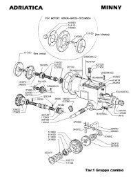
4.3 Technical description of the machine<br />
10<br />
<strong>TRIMMER</strong>-<strong>50</strong><br />
<strong>TRIMMER</strong>-<strong>60</strong><br />
The base of the machine is a rigid frame on which a combustion engine is placed.<br />
The machine is equipped with covers against flying cut material. A screen of plastic<br />
canvas placed between the wheels prevents flying chips. Tubular handlebars have an<br />
ergonomic shape and their height is adjustable. They are equipped with a control<br />
horizontal bar of string head drive clutch, lever for axle tilt arrestment and accelerator<br />
lever. The string head is driven through a V-belt. The drive is switched on by the<br />
tension pulley via the control horizontal bar. Working tool is a string head with two<br />
strings, whose design makes it possible to adjust the cutting height by realigning<br />
distance rings. The strings are fastened by passing them through the string holder and<br />
tightening. Other working attachments that can be used in place of the string head are<br />
saw blade and mowing disks (with 3-4 teeth), which are to be installed on the machine<br />
through the friction overunning clutch onto the steel hub. The mower axle can be tipped<br />
to sides (left, right) which facilitates final trimming near fences and walls. Arrestment<br />
of side d which a gear-box is tipping is controlled by a lever located on the handlebars.<br />
The wheels have plastic felloes with heavy-duty solid rubber tyres.<br />
Ochranná plenta<br />
Řezač struny<br />
Ovládací hrazda spojky pohonu<br />
Páčka aretace nápravy<br />
Páčka akcelerátoru<br />
Řídítka<br />
Kloub nastavení řidítek<br />
Pojezdová kola<br />
Krytování
Figure 1<br />
5. Instructions for use<br />
5.1 Machine assembly<br />
Páčka aretace nápravy<br />
Páčka akcelerátoru<br />
Ovládací hrazda spojky pohonu<br />
Řídítka<br />
Kloub nastavení řidítek<br />
Pojezdová kola<br />
Krytování<br />
Struna<br />
Strunová hlava<br />
Ask your dealer to provide unpackaging of the machine and briefing.<br />
<strong>TRIMMER</strong>-<strong>50</strong><br />
<strong>TRIMMER</strong>-<strong>60</strong><br />
Grip points:<br />
a) Front: - Front edge of the lower casing;<br />
b) Rear: - Handlebar grips or machine frame cross-bar when the handlebars are folded.<br />
If you assemble the machine yourself, follow the below instructions:<br />
1. Take the machine out from the box.<br />
2. Loosen the plastic rosebits of handlebars joints and turn the handlebars so that the<br />
handrails point to the rear of the machine. Adjust the height of the handrail grip so<br />
that it can be easily reached. tighten the rosebits.<br />
3. Fasten the Bowdens to handlebars by means of plastic tightening tapes.<br />
4. Make the engine ready for operation according to the manual for its use.<br />
! The machine is delivered without operational engine fillings!<br />
11
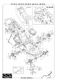
5.2 Putting into operation<br />
12<br />
<strong>TRIMMER</strong>-<strong>50</strong><br />
<strong>TRIMMER</strong>-<strong>60</strong><br />
Read the instruction for engine use thoroughly! You can prevent a possible<br />
damage to the engine.<br />
1. Fill the engine with the prescribed types and volumes of oil and petrol.<br />
2. Instructions for making the motor ready for starting and instructions for proper<br />
engine start see the operating manual for engine use.<br />
3. Let the new or cold engine running for about 1 min with the accelerator lever in the<br />
MAX position.<br />
MAX<br />
MIN STOP Axle arrestment lever<br />
CHOKE only<br />
in<br />
<strong>TRIMMER</strong>-<strong>60</strong><br />
Figure 2<br />
5.3 Starting the mowing tool<br />
Accelerator lever<br />
Control horizontal<br />
bar<br />
1. Start the engine (if it is cold, let it running for about 1 min to warm up). At doing<br />
this, follow the instructions presented in the operating manual for engine use.<br />
2. Set-up maximum engine rotations by means of accelerator lever.<br />
3. Grasp the handlebars with your left hand and pull the control horizontal bar to the<br />
handlebars with your right hand until the string head starts turning. Hold the<br />
horizontal bar near the grip at working.<br />
The start of the string head can be accompanied with rattle or whistle due to a partial<br />
slippage of the V-belt during the switching. The phenomenon usually disappears after<br />
the belt has run in.<br />
! The aerodynamic noise (whizz) resulting from a high circumferential speed of<br />
the string is characteristic of the string mowers. The phenomenon cannot be<br />
rectified and does not signal any defect or failure!
<strong>TRIMMER</strong>-<strong>50</strong><br />
<strong>TRIMMER</strong>-<strong>60</strong><br />
Note: In a new or cold engine, engine stalling may occur at the several first string<br />
head drive starts. The phenomenon disappears after the engine has warmed up.<br />
5.4 Machine travel<br />
The machine is not equipped with the travel and it must be therefore pushed into the<br />
engagement.<br />
5.5 Machine stop<br />
• The string head drive will switch off when the horizontal bar on the handlebars is<br />
released.<br />
• The engine will switch off when the lever is moved into the STOP position.<br />
! Prior to performing any activities in the near vicinity of the machine, switch off<br />
the engine and wait until the string head stops! Always switch the engine off before<br />
leaving the machine.<br />
! Don’t stop the running out string head by pressing it against the ground (e.g.<br />
lifting the rear machine part by pulling on the handlebars).<br />
! When the string head runs out, hold the handlebars firm so that the machine<br />
could not move to the side due to the friction of support disk on the surface!<br />
! Never let the engine running at maximum speed or idling with the string head<br />
drive gear clutch switched off for a long time! Machine drive components (V-belt,<br />
belt pulley, clutch pulley, etc.) might get damaged!<br />
! In the case of any critical situation, release your hold on the handlebars<br />
immediately. The horizontal bar will return to its zero position, the string head<br />
will come to a stop (while the engine is still running at adjusted rotations; this is<br />
why it is to be switched off by pushing the accelerator lever into the STOP position<br />
as soon as possible!)<br />
5.6 Working with the machine<br />
5.6.1 Mowing grass stands<br />
! Prior to the machine use, the stand must be cleared of solid bodies such as<br />
stones, wires, loose construction debris, etc., which could be flung or might<br />
otherwise damage the machine. Should these be impossible to remove, pass the<br />
places by in order to prevent impacts on the working tool and its premature wear<br />
or destruction.<br />
! Mowing engagement width has to be at all times accommodated to the stand<br />
density!<br />
13
14<br />
<strong>TRIMMER</strong>-<strong>50</strong><br />
<strong>TRIMMER</strong>-<strong>60</strong><br />
Adjust the engine speed at maximum, let the string head run on maximum rotations<br />
and then drive the machine against the stand to be cut. The mown stand will be thrown<br />
onto the right side of the machine (as viewed by the operator). Should the stand be low<br />
and not too dense or lodged, you can proceed by pushing the machine continually and<br />
slowly forward.<br />
In the case that the grass stand is high, dense or lodged, the styl of work will be<br />
different. Drive the machine into the stand, stop it, and cut the stand out by moving the<br />
machine from side to side in oscillations of about <strong>60</strong>° (as if mowing with a scythe).<br />
Caution! When cutting, the string head should be at all times slightly above the ground<br />
(2-5 cm). If this rule is not observed, the machine will be forced to sides due to the<br />
contact of the rotating string head with the ground. The phenomenon can be rectified by<br />
adding a guide wheel. Leading the string head low above the ground provides for a good<br />
balance of the machine.<br />
5.6.2 String installation procedure<br />
1) Cut a string length of max. 45 cm<br />
(<strong>TRIMMER</strong> <strong>50</strong>) or <strong>50</strong> cm<br />
(<strong>TRIMMER</strong> <strong>60</strong>) from the coil and<br />
freely bend the string to have two<br />
half-lengths.<br />
Figure 3<br />
3) Pass the loose ends through the middle<br />
eye of the holder and below the loop.<br />
Figure5<br />
2) Pass the string ends through the outer eyes<br />
of the holder<br />
Figure 4<br />
4) Tighten firm by pulling out.<br />
Figure 6<br />
! After having installed a new string, always make sure that the string does not<br />
overlap the cutter by more than 1 cm. If so, cut it by scissors or by knife. The<br />
string will shorten to its precise length after the string head has started rotating.<br />
! Use only the string size and type recommended by the manufacturer of the<br />
machine.
<strong>TRIMMER</strong>-<strong>50</strong><br />
<strong>TRIMMER</strong>-<strong>60</strong><br />
! Always replace both the strings. Poor balance of the string head may result in a<br />
machine damage.<br />
Caution! When mowing in the stand with a lot of solid objects, near walls, fences or<br />
curb stones, a string breakage occurs more frequently, resulting in the reduction of<br />
machine engagement width or in the complete string loss. It is advised that the operator<br />
has a sufficient amount of spare strings on him.<br />
! When working with the <strong>TRIMMER</strong>-<strong>50</strong> machine, don’t increase the machine<br />
engagement width above <strong>50</strong> cm. The engine may be damaged due to overloading.<br />
! When working with the <strong>TRIMMER</strong>-<strong>60</strong> machine, don’t increase the machine<br />
engagement width above 58 cm. Danger of damage to the string head protective<br />
casing.<br />
5.6.3 Adjusting the mowing height<br />
! The adjustment is to be made with the engine switched off and the spark plug<br />
cable disconnected.<br />
The machine is equipped with a string head which enables adjustment of 3 mowing<br />
heights. The mowing height adjusted by the manufacturer is the lowest one.<br />
Mowing height adjustment procedure:<br />
1. Put the machine onto a firm base so that you have a good access to it. Secure the<br />
machine against spontaneous movement.<br />
2. Loosen and unscrew the bolt with fillers (barrel spanner No. 16 supplied with the<br />
machine) fastening the string head assembly to the shaft.<br />
3. Dismount the lower support disk, disk with strings and distance rings.<br />
4. Reassemble the string head to the required mowing height according to figures 7, 8<br />
and 9.<br />
5. Screw the bolt back and tighten it properly (tightening moment is 15 N.m)<br />
Minimum<br />
Medium Maximum<br />
Figure 7 Figure 8 Figure 9<br />
15
5.6.4 Tilting of the machine<br />
16<br />
<strong>TRIMMER</strong>-<strong>50</strong><br />
<strong>TRIMMER</strong>-<strong>60</strong><br />
Machine tilting to sides (out of machine axis) is used for final trimming near curb<br />
stones, fences or walls (edges in general), i.e. at places impossible to reach with a<br />
common grass mower.<br />
Tilting is to be made as follows:<br />
1. Press the axle arrestment lever (see Fig. 1) down with the thumb of your right hand<br />
until the arrestment pin is released.<br />
2. Tilt the machine mildly backwards and turn it by means of handlebars to the desired<br />
side (left or right). The machine axis is a turning point at this moment.<br />
3. Release the axle arrestment lever and in the case that the arrestment pin does not fall<br />
in, swing the machine slightly until the pin falls in. Return the machine into its<br />
working position.<br />
5.6.5 Problems at cutting<br />
Tilting to the left Tilting to the right<br />
Figure 10 Figure 11<br />
• If the engine is markedly loosing speed (engine is choking), the engagement width<br />
and the travel speed should be accommodated to the density and height of the grass<br />
stand.<br />
• If the mown stand width does not correspond to the nominal engagement, check the<br />
strings for intactness or replace them with new ones.<br />
• If the string head rotations do not reach nominal values without load (engine is<br />
choking), remove the grass wound up onto the string head hub. If the engine is still<br />
choking, check its condition and make sure that the string head can freely turn.
5.7 Advised accessories<br />
<strong>TRIMMER</strong>-<strong>50</strong><br />
<strong>TRIMMER</strong>-<strong>60</strong><br />
A Guide wheel (Order.No. 3878) is advised to improve the leading of the string<br />
head above the terrain. A set of Disk holder (Order.No. 3881) is recommended for<br />
greater applicability of the machine to join the mowing disks or saw blades. The<br />
specification of disks see chapter Technical specifications.<br />
5.7.1 Guide wheel<br />
The guide wheel serves for a better guidance of the machine at cutting flat surfaces<br />
with low stand heights and without hidden solid objects. It is to be inserted into the<br />
holder in the front part of the machine and secured with the bolt.<br />
5.7.2 Mowing disks and saw blades<br />
5.7.2.1 Assembling the disks<br />
! Be careful when exchanging the working tools. The cutting edges are sharp.<br />
Protect your hands with the working gloves.<br />
! The exchange should always be made with the engine switched off and the spark<br />
plug cable disconnected.<br />
1. Loosen and unscrew the bolt holding the string head and dismount the string head<br />
including the distance rings.<br />
2. Insert the steel hub, friction washer, mowing disk or saw blade and fillers according<br />
to Figure 12.<br />
3. Tighten the bolt with the barrel spanner No. 16. Tightening moment is 15 N.m.<br />
When loosening and tightening the bolt, put on the round iron (ZNAČKA!) 6 mm or<br />
the imbus wrench No. 6 through the holder on the hub and tube on the machine frame so<br />
that the disk does not turn over.<br />
Hub<br />
Friction washer<br />
Packing piece-lens<br />
Filler<br />
Bolt<br />
Mowing<br />
disk or saw<br />
blade<br />
Belleville washer<br />
Figure 12<br />
17
5.7.2.2 Working with the saw blade<br />
18<br />
<strong>TRIMMER</strong>-<strong>50</strong><br />
<strong>TRIMMER</strong>-<strong>60</strong><br />
The saw blade is meant for undercutting the self-seeded trees and shrubs up to a<br />
(ZNAČKA!) of max. 5 cm.<br />
• Set-up maximum speed and switch on the working tool drive see chapter Starting<br />
the mowing tool.<br />
• Drive the saw blade slowly into the stem and cut the tree off while pushing on the<br />
machine and balancing the saw blade side reaction. (Fig. 13)<br />
! Protect your eyes and face by using approved working aids! It is necessary to<br />
use ear protectors to CSN EN 352-1. To protect eyes and face use the means of<br />
personal protection to CSN EN 1731.<br />
Figure 13<br />
! Be careful at cutting out the trees and shrubs since they can fall onto the ma-<br />
chine operator.<br />
! If the blade gets “seized“, release your hold on the clutch control horizontal bar<br />
without a delay and pull the machine out from the engagement. Switch the engine<br />
off and check fastening of the blade and its intactness.<br />
It is not advised to use the saw blade and the guide wheel at the same time.<br />
5.7.2.3 Working with the mowing disk<br />
The style of work is different from the cutting with the string head. Drive the<br />
machine into the grass stand, stop it and mow the stand by swinging the machine from<br />
side to side at about <strong>60</strong>° (as if cutting with a scythe).
6. Maintenance, care and storage<br />
<strong>TRIMMER</strong>-<strong>50</strong><br />
<strong>TRIMMER</strong>-<strong>60</strong><br />
To ensure a long-term satisfaction with our product, it must be given proper care and<br />
maintenance. Regular maintenance of the machine will prevent its early wear ensuring at<br />
the same time a correct functioning of all its parts.<br />
Follow all instructions for intervals of machine maintenance and adjustment. It is<br />
advices that you keep records on the number of machine working hours and on the<br />
conditions in which the machine was working (for service purposes). Similarly as the<br />
current maintenance, the after-season maintenance should be entrusted to one of our<br />
authorized service workshops.<br />
6.1 Lubrication<br />
6.1.1 Engine oil replacement<br />
! When replacing oils, follow the basic hygienic principles, regulations and laws on<br />
environment protection.<br />
The information on the oil replacement can be found in the operating manual for<br />
engine use. To drain oil either tilt the machine onto the side with the pour-in neck with<br />
oil gauge or dismount the engine from the machine.<br />
6.1.2 Lubrication points<br />
Machine lubrication during the<br />
season<br />
Tightening pulley arm<br />
pin ( after disassembly of<br />
upper casing)<br />
After the<br />
season<br />
min 2x Yes<br />
Bearings of travel wheels as required Yes<br />
String head drive gear<br />
clutch litz wire<br />
here<br />
min 2x Yes -<br />
19
6.1.2 Lubrication and assembly of wheels<br />
20<br />
<strong>TRIMMER</strong>-<strong>50</strong><br />
<strong>TRIMMER</strong>-<strong>60</strong><br />
• Underlay the machine so that the wheels can freely turn. The machine must be<br />
secured against spontaneous movement.<br />
• Dismount the nut and the outer cone by using the spanner No. 15. Remove the<br />
wheel from the axis.<br />
• Press the bearings out of the hub in the plastic rim. Wash them from dirt and old<br />
grease.<br />
• Fill the bearings inside with a new grease (e.g. for water pumps) and press them<br />
back into the hub in the plastic rim of the wheel. Grease the inner and outer cones as<br />
well.<br />
• Put the wheel back and screw the outer cone. Screw the nut and tighten the cone<br />
against the nut so that the wheel can freely turn but does not show any greater side<br />
clearance.<br />
6.1.3 Maintenance of tension pulley litz wire<br />
In order to guarantee a low operating force on the operating horizontal bar<br />
controlling the drive of the string head, it is adviceable to lubricate the litz wire in the<br />
Bowden at least 2x during the season with an oil available in atomiser (e.g. SILKAL,<br />
MD Spray, WD40).<br />
6.2 Tightening of bolted connections<br />
Check the tightening of bolted connections. Prior to each use of the machine, check<br />
the bolt fastening the string head to the shaft for tightness; check the tightness of bolts<br />
fastening the string holder to the string head.<br />
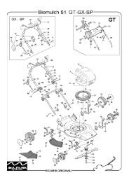
6.3 Replacement of V-belt and adjustment of tension pulley<br />
The V-belt should be replaced according to its wear (cracked sides, torn belt, sides<br />
worn out down to belt carrier fibres, belt pulled out of shape) or after about 100 hours of<br />
operation at the maximum. In this machine, the belt stretched to maximum is considered<br />
a belt in which the distance between the internal belt surfaces is lesser than 7 mm (Fig.<br />
15 bottom) with the pressed horizontal bar of string head drive clutch.<br />
Problem Cause Remedial action<br />
String head does not turn<br />
Tightening pulley does not stress Set-up tightening pulley by<br />
the belt sufficiently<br />
means of adjustment bolt (see<br />
Fig. 14)<br />
Litz wire fallen out from Put the litz wire back<br />
tightening pulley lever<br />
V-belt fallen behind tightening<br />
pulley or down from belt pulley<br />
Put the belt back<br />
V-belt torn Replace the belt with a new one<br />
Excessive belt extension (see Fig.<br />
15 bottom)<br />
Replace the belt with a new one
<strong>TRIMMER</strong>-<strong>50</strong><br />
<strong>TRIMMER</strong>-<strong>60</strong><br />
The replacement procedure is as follows:<br />
a) Drain petrol from the engine tank. Dismount the accelerator lever (2x spanner No.<br />
8) from the handlebars. Bowden cable should never be dismounted from the<br />
control on the engine!<br />
b) Unscrew three safety nuts (spanner No. 13) on the engine flange and pull the engine<br />
out from the machine frame upwards. Never use force to pull the engine from the<br />
frame!<br />
! Never put the engine on the side. Oil might get into the exhaust or into the air<br />
cleaner. The best engine seating is with the lower flange dwelling on two lintels<br />
which are at least 7 cm high.<br />
c) Dismount the upper casing (spanner No. 8, spanner No. 13). Dismount the bolt in<br />
front of the driven belt pulley (spanner No. 10). Take the old V-belt off and replace<br />
it with a new one. V-belt marking is GATES A52 BareBack.. It is also possible to<br />
use an equivalent V-belt made by other manufacturers at a size of A13x1320 Li<br />
(Li=internal belt length). However, the belt must be made without rubber on belt<br />
sides! Only this belt model will guarantee that the string head drive start will be<br />
continuous at engaging the clutch.<br />
! Should a different belt model be used, the machine manufacturer does not bear<br />
any liability for the correct and full functioning of the gear and for damage caused<br />
by the incorrect belt type!<br />
d) Put the engine back to its place, slide the belt into the groove in the belt pulley on<br />
the engine and check if the belt passes correctly around the guides. Screw the engine<br />
by using three safety nuts with flat washers. Screw the accelerator lever back onto<br />
the handlebars.<br />
e) Check the operation of the tightening pulley. With the horizontal bar on the<br />
handlebars being completely pressed down, the pulley must ensure a sufficient belt<br />
tension (spring on the litz wire being extended by about 10 mm as compared with<br />
the normal condition). Possible corrections are to be made by means of the<br />
adjustment bolt (see Fig.14). Use two spanners No. 10 or No. 9. With the lever<br />
switched off, the pulley must be leaning against the stop on the engine plate (Fig. 15<br />
top) and the litz wire in the Bowden of the tension pulley can be slightly slack. In<br />
the case that the adjustment bolt is completely unscrewed and it is necessary to<br />
tighten the V-belt, the spring on the cable can be hooked into the front hole on the<br />
tension pulley arm and to set-up the belt tension once again.<br />
f) Screw the bolt back in front of the driven belt pulley and mount back the upper<br />
casing.<br />
21
6.4 Table of service operations<br />
22<br />
Driven belt<br />
pulley<br />
7 mm<br />
V-belt<br />
Obr.14<br />
Figure 14<br />
Figure 15<br />
<strong>TRIMMER</strong>-<strong>50</strong><br />
<strong>TRIMMER</strong>-<strong>60</strong><br />
Operation During the season After<br />
season<br />
the<br />
Engine oil check prior to each use **<br />
Engine air filter check prior to each use check<br />
String holder check prior to each use<br />
***<br />
check<br />
Check of intactness of upper and prior to each use check<br />
lower disk<br />
***<br />
Check of V-belt stress as required check<br />
V-belt condition check as required check ****<br />
Cleaning of wheel hubs and - yes<br />
replacement of lubrication grease<br />
Cleaning of the machine from dirt<br />
and plant residues<br />
always after the<br />
end of work<br />
yes<br />
Driven belt<br />
pulley ( engine)<br />
Tension pulley<br />
Stop
<strong>TRIMMER</strong>-<strong>50</strong><br />
<strong>TRIMMER</strong>-<strong>60</strong><br />
**<br />
Oil replacement intervals see Operating manual for engine;<br />
***<br />
In the case of damage (even at cutting) – cracks, bending, breakage etc. – repair<br />
required immediately!<br />
****<br />
or replacement after about 100 hours.<br />
6.5 Washing and cleaning of the machine<br />
! At cleaning and washing the machine, proceed to observe valid regulations and<br />
laws on the protection of water courses and other water resources against pollution<br />
or contamination with chemical substances.<br />
! Never wash the engine with a stream of water! Electric equipment might fail<br />
when starting the engine.<br />
All dirt, debris and plant residues should be removed from the machine after the end<br />
of the season. Check the intactness of working tools (or replace them if necessary). The<br />
travel wheels should be dismounted from the axle once in a season, cleaned and the hub<br />
inside filled with a new filling of plastic lubricant.<br />
! The engine has to be switched off and the cable termination to spark plug<br />
disconnected!<br />
6.6 Storage<br />
Prior to a longer storage, clean the machine from all dirt, debris and plant residues.<br />
Repair the damaged places on painted machine parts. Prevent the access of<br />
unauthorized persons to the machine. Protect the machine from weather impacts but<br />
don’t use the air-tight protection due to a possibly increased corrosion under it.<br />
6.7 Liquidation of packaging and machine after service life expiration<br />
After unpacking the machine, you are obliged to provide for the liquidation of<br />
packaging with using the secondary raw-materials according to Waste Law No.<br />
185/2001 Gaz. (and its possible further amendments) and with respect to the decrees of<br />
local town or municipal authorities.<br />
The following procedure is recommended for machine liquidation after the end of its<br />
service life:<br />
* Dismount all parts from the machine that still can be used.<br />
* Dismount the plastic machine parts and the parts of non-ferrous metals. The stripped<br />
machine remainder and the dismounted parts are to be liquidated according to Waste<br />
Law No. 185/2001 Gaz. (and its possible further amendments) and with respect to the<br />
decrees of local town or municipal authorities.<br />
23
7 Instructions for ordering spare parts<br />
24<br />
<strong>TRIMMER</strong>-<strong>50</strong><br />
<strong>TRIMMER</strong>-<strong>60</strong><br />
The following data are to be used for easier identification when ordering the spare parts:<br />
1. Machine type, engine type, machine serial number and year of manufacture;<br />
2. Ordering number given by manufacturer and its name in the component list;<br />
3. Number of ordered pieces separately for each item;<br />
4. Precise address, telephone number, fax number or e-mail address;<br />
5. If you are not certain about the correct identification of the component, send the<br />
damaged component either to the nearest service shop or to the manufacturer;<br />
In the case of any confusions concerning the spare parts or technical issues, the<br />
VARI a.s. commercial, customer-service or technical departments are prepared to<br />
answer all your inquiries.<br />
8 Contact to manufacturer<br />
VARI, a.s. Telephone: (+42) 0324 <strong>60</strong>7111<br />
Opolanská 3<strong>50</strong> Fax: (+42) 0324 6775<strong>50</strong><br />
Libice nad Cidlinou (+42) 0324 <strong>60</strong>7264<br />
CZECH REPUBLIC E-mail: vari@vari.cz<br />
289 07 internet: www.vari.cz