NIKE Mini kW Special - Immergas
NIKE Mini kW Special - Immergas
NIKE Mini kW Special - Immergas

Create successful ePaper yourself
Turn your PDF publications into a flip-book with our unique Google optimized e-Paper software.
1 SPECIFICATIONS - <strong>NIKE</strong> <strong>Mini</strong> <strong>kW</strong> <strong>Special</strong><br />
Wall-hung conventional flue boiler for central heating and instant<br />
production of domestic hot water (Appliance type B 11BS ) with a nominal<br />
heating output of 24 <strong>kW</strong> (20,640 kcal/h) and 27.9 <strong>kW</strong> (24,000<br />
kcal/h), forced circulation.<br />
The boiler comprises:<br />
• a stainless steel multigas burner with 12 (mod. 24) or 14 ramps<br />
(mod. 28), with aspirated air featuring ignition electrodes and an<br />
ionisation detection electrode, electric gas valve with double shutter<br />
and built-in modulating coil;<br />
• high performance primary gas/water exchanger in copper, consisting<br />
of four pipes connected in series fitted in a lamellar battery protected<br />
by a corrosion proof alloy;<br />
• combustion chamber in steel sheet insulated internally with ceramic<br />
panels;<br />
• draught diverter in steel sheet with a device to protect against<br />
draught and wind and a flue control device;<br />
• secondary water/water exchanger for the production of domestic<br />
hot water made in stainless steel with 14 (mod. 24) or 16 plates<br />
(mod. 28);<br />
• hydraulic unit comprising a 3-way electric valve, an adjustable speed<br />
circulation pump with built-in air separator, an automatic by-pass,<br />
a system draining fitting and a cock for filling the system;<br />
• d.h.w. flow switch for detecting when hot water is being drawn;<br />
• 6-litre capacity system diaphragm expansion vessel (actual capacity<br />
4.5 litres) for model 24 or 7.5-litre capacity (actual capacity 4.5)<br />
for model 28 with preload at 1.0 bar, 3-bar system safety valve and<br />
manometer;<br />
• overtemperature safety thermostat;<br />
• ionisation controlled electronic ignition;<br />
• knob for setting central heating temperature, knob for setting<br />
domestic hot water temperature, main selector with functions<br />
1<br />
<strong>NIKE</strong> <strong>Mini</strong> <strong>kW</strong> <strong>Special</strong><br />
Wall-mounted instant boilers<br />
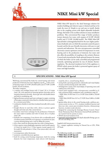
<strong>NIKE</strong> <strong>Mini</strong> <strong>kW</strong> <strong>Special</strong> is the ideal <strong>Immergas</strong> solution for<br />
modern building and wherever space is limited and has to be<br />
made the most of. Simple to use and easy to install, thanks<br />
also to the coupling system with depth adjustable hydraulic<br />
fittings, this boiler is the excellent solution to many installation<br />
problems. This conventional flue range of boilers produces<br />
instant domestic hot water, with outputs of 24 <strong>kW</strong> (20,640<br />
kcal/h) and 27.9 <strong>kW</strong> (24,000 kcal/h). The <strong>NIKE</strong> <strong>Mini</strong> <strong>kW</strong><br />
<strong>Special</strong> boiler is distinguished both for the new, higher performance<br />
hydraulic unit, on which the automatic system by-pass is<br />
located, and for the user-friendly electronics with easy-to-read<br />
controls and indications. The new microprocessor controlled<br />
electronics ensures optimum control of temperatures in room<br />
heating and in the production of domestic hot water and<br />
also offers the possibility of coupling to the exclusive Remote<br />
Control and external probe (both optional features) by means<br />
of which the boiler can be easily controlled and programmed<br />
remotely, optimising operation by way of climatic thermoregulation.<br />
The electrical insulation level of this appliance is<br />
IPX4D which means the boiler is protected against sprays of<br />
water and high humidity.<br />
(stand-by, d.h.w., central heating, Reset);<br />
• setting boiler operating parameters with knobs and visual display<br />
of status and functioning mode with LEDs;<br />
• self-diagnostics system with visual display of operating status and<br />
malfunctions with LEDs;<br />
• control panel equipped with a microprocessor controlled p.c.b.<br />
with continuous flame modulation and a modulation range of:<br />
- <strong>NIKE</strong> <strong>Mini</strong> 24 <strong>kW</strong> from 9.3 to 24 <strong>kW</strong> (from 8,000 to 20,640<br />
kcal/h);<br />
- <strong>NIKE</strong> <strong>Mini</strong> 28 <strong>kW</strong> from 10.5 to 27.9 <strong>kW</strong> (from 9,000 to 24,000<br />
kcal/h);<br />
• ignition delay device in the central heating mode, antifreeze protection<br />
system (as low as -5°C), circulator antiblock function and<br />
three-way valve, system post-circulation function, chimneysweep<br />
function, circulator mode selection;<br />
• designed for connecting the <strong>Immergas</strong> Remote Control, Timer/<br />
Room Thermostat, Room Thermostat, External Probe and Electronic<br />
Control Unit for systems in zones;<br />
• IPX4D electrical insulation level.<br />
• (optional) connecting group with depth adjustable fittings, gas cut<br />
off cock and filling valve.<br />
Supplied with bottom protection cap.<br />
II 2H3+ category appliance running on Natural Gas or LPG. With<br />
CE mark.<br />
The following models are available:<br />
• <strong>NIKE</strong> <strong>Mini</strong> 24 <strong>kW</strong> <strong>Special</strong> cod. 3.018871<br />
• <strong>NIKE</strong> <strong>Mini</strong> 28 <strong>kW</strong> <strong>Special</strong> cod. 3.018921
2<br />
<strong>NIKE</strong> <strong>Mini</strong> <strong>kW</strong> <strong>Special</strong><br />
2 MAIN COMPONENTS - <strong>NIKE</strong> <strong>Mini</strong> 24 <strong>kW</strong> <strong>Special</strong><br />
LEGEND:<br />
1 - Burner<br />
2 - D.h.w. flow switch<br />
3 - Gas valve<br />
4 - Filling valve<br />
5 - Flue safety thermostat<br />
6 - Flue hood<br />
7 - Flow probe<br />
8 - Safety thermostat<br />
9 - System expansion vessel<br />
10 - Combustion chamber<br />
90° gas cock axis - wall dimension = 90 mm<br />
11 - Boiler pump<br />
12 - 3-bar safety valve<br />
13 - Automatic by-pass<br />
14 - 3-way valve (motorized)<br />
15 - Draining valve<br />
16 - Primary heat exchanger<br />
17 - Ignition and detection electrodes<br />
18 - Automatic vent valve<br />
19 - D.h.w. heat exchanger
3<br />
<strong>NIKE</strong> <strong>Mini</strong> <strong>kW</strong> <strong>Special</strong><br />
2.1 MAIN COMPONENTS - <strong>NIKE</strong> <strong>Mini</strong> 28 <strong>kW</strong> <strong>Special</strong><br />
LEGEND:<br />
1 - Burner<br />
2 - D.h.w. flow switch<br />
3 - Gas valve<br />
4 - Filling valve<br />
5 - Flue safety thermostat<br />
6 - Flue hood<br />
7 - Flow probe<br />
8 - Safety thermostat<br />
9 - System expansion vessel<br />
10 - Combustion chamber<br />
90° gas cock axis - wall dimension = 150 mm<br />
11 - Boiler pump<br />
12 - 3-bar safety valve<br />
13 - Automatic by-pass<br />
14 - 3-way valve (motorized)<br />
15 - Draining valve<br />
16 - Primary heat exchanger<br />
17 - Ignition and detection electrodes<br />
18 - Automatic vent valve<br />
19 - D.h.w. heat exchanger
4<br />
<strong>NIKE</strong> <strong>Mini</strong> <strong>kW</strong> <strong>Special</strong><br />
3 MAIN DIMENSIONS - <strong>NIKE</strong> <strong>Mini</strong> 24 <strong>kW</strong> <strong>Special</strong><br />
Model<br />
<strong>NIKE</strong> <strong>Mini</strong> 24 <strong>kW</strong> <strong>Special</strong><br />
Height (mm)<br />
770<br />
Width (mm)<br />
450<br />
3.1 CONNECTIONS<br />
Model<br />
<strong>NIKE</strong> <strong>Mini</strong> 24 <strong>kW</strong><br />
<strong>Special</strong><br />
Flow<br />
M<br />
3/4"<br />
Return<br />
R<br />
3/4"<br />
Hot outlet<br />
AC<br />
1/2"<br />
Depth (mm)<br />
250<br />
Cold inlet<br />
AF<br />
1/2"<br />
Gas<br />
G<br />
3/4"<br />
Flue Ø (mm)<br />
130<br />
Note: Coupling system (OPTIONAL)<br />
Expansion vessel<br />
Litres<br />
6 (real 4.5)
5<br />
<strong>NIKE</strong> <strong>Mini</strong> <strong>kW</strong> <strong>Special</strong><br />
4 MAIN DIMENSIONS - <strong>NIKE</strong> <strong>Mini</strong> 28 <strong>kW</strong> <strong>Special</strong><br />
Model<br />
<strong>NIKE</strong> <strong>Mini</strong> 28 <strong>kW</strong><br />
Height (mm)<br />
770<br />
Width (mm)<br />
450<br />
4.1 CONNECTIONS<br />
Model<br />
<strong>NIKE</strong> <strong>Mini</strong> 28 <strong>kW</strong><br />
<strong>Special</strong><br />
Flow<br />
M<br />
3/4"<br />
Return<br />
R<br />
3/4"<br />
Hot outlet<br />
AC<br />
1/2"<br />
Depth (mm)<br />
310<br />
Cold inlet<br />
AF<br />
1/2"<br />
Gas<br />
G<br />
3/4"<br />
Flue Ø (mm)<br />
130<br />
Note: Coupling system (OPTIONAL)<br />
Expansion vessel<br />
Litres<br />
7.5 (real 4.5)
5 PUMP HEAD AND FLOW RATE GRAPH<br />
The "<strong>NIKE</strong> <strong>Mini</strong> <strong>kW</strong> <strong>Special</strong>" boilers are supplied with the<br />
pump incorporated. The circulation pump is already fitted with<br />
a condenser.The graph shows the system’s available head (with<br />
5.1 PUMP - <strong>NIKE</strong> <strong>Mini</strong> 24 <strong>kW</strong> <strong>Special</strong><br />
Head (kPa)<br />
WILO OTSL 15/5-3<br />
5.2 PUMP - <strong>NIKE</strong> <strong>Mini</strong> 28 <strong>kW</strong> <strong>Special</strong><br />
Head (kPa)<br />
WILO OTSL 15/6.7-3<br />
A = Head available to the system at third speed (with automatic by-pass).<br />
B = Head available to the system at second speed (with automatic by-pass).<br />
6<br />
<strong>NIKE</strong> <strong>Mini</strong> <strong>kW</strong> <strong>Special</strong><br />
automatic by-pass) which depends on the flow rate.<br />
To optimize boiler operation, the circulation pump in new systems<br />
(single-pipe and module) should be used at top speed.<br />
B<br />
B<br />
A<br />
A<br />
Flow rate l/h<br />
Flow rate l/h<br />
Head (m H 2 O)<br />
Head (m H 2 O)
6 WIRING DIAGRAM - <strong>NIKE</strong> <strong>Mini</strong> 24-28 <strong>kW</strong><br />
AMBIENT THERMOSTAT OR REMOTE CONTROL<br />
The boiler is pre-engineered for installation of the Amico Remote<br />
Control (CAR), which must be connected to terminals<br />
42 and 43 in compliance with the polarity and eliminating<br />
jumper X40.<br />
The boiler is pre-engineered for installation of the roomther- <br />
<br />
<br />
<br />
<br />
<br />
<br />
<br />
<br />
<br />
<br />
<br />
<br />
LEGEND:<br />
A5 - CAR interface board<br />
B1 - Flow probe<br />
B4 - External probe (optional)<br />
CAR - Comando Amico Remoto remote control<br />
(optional)<br />
CRD - Digital remote control (optional)<br />
E1 - Ignition electrodes<br />
E2 - Detection electrode<br />
E4 - Safety thermostat<br />
E6 - Flue thermostat<br />
F1 - Neutral fuse<br />
F2 - Line fuse<br />
<br />
<br />
7<br />
<strong>NIKE</strong> <strong>Mini</strong> <strong>kW</strong> <strong>Special</strong><br />
mostat (S20), programmable On/Off thermostat, programmable<br />
timer or a Digital Remote Control (CRD), which must be<br />
connected to terminals 40 - 41 and remove the jumper X40.<br />
The external probe (B4) must be connected to terminals 38<br />
and 39 on the integrated electronic board.<br />
<br />
<br />
<br />
<br />
<br />
<br />
<br />
<br />
<br />
<br />
<br />
<br />
<br />
<br />
M1 - Boiler pump<br />
M30 - 3-way valve<br />
R5 - D.h.w. temperature trimmer<br />
R6 - Heating temperature trimmer<br />
R10 - Main switch<br />
S4 - D.h.w. flow switch<br />
S8 - Gas type selector<br />
S20 - Room thermostat (optional)<br />
T2 - Ignition transformer<br />
X40 - Room thermostat jumper<br />
Y1 - Gas valve<br />
Y2 - Gas valve modulator
8<br />
<strong>NIKE</strong> <strong>Mini</strong> <strong>kW</strong> <strong>Special</strong><br />
7 HYDRAULIC LAYOUT - <strong>NIKE</strong> <strong>Mini</strong> 24-28 <strong>kW</strong> <strong>Special</strong><br />
LEGEND:<br />
1 - D.h.w. flow switch<br />
2 - Flow limiter<br />
3 - Filling valve<br />
4 - Gas valve<br />
5 - Burner<br />
6 - Primary heat exchanger<br />
7 - Flue hood<br />
8 - Flue safety thermostat<br />
9 - Flow probe<br />
10 - Safety thermostat<br />
11 - System expansion vessel<br />
12 - Automatic vent valve<br />
13 - Boiler pump<br />
14 - D.h.w. heat exchanger<br />
15 - 3-way valve (motorized)<br />
16 - Automatic by-pass<br />
17 - Draining valve<br />
18 - 3-bar safety valve
9<br />
<strong>NIKE</strong> <strong>Mini</strong> <strong>kW</strong> <strong>Special</strong><br />
8 TECHNICAL SPECIFICATIONS - <strong>Mini</strong> 24-28 <strong>kW</strong> <strong>Special</strong><br />
Maximum nominal heat input <strong>kW</strong> (kcal/h) 26.7 (22,933) 30.9 (26,571)<br />
Maximum nominal heat output <strong>kW</strong> (kcal/h) 24.0 (20,640) 27.9 (24,000)<br />
<strong>Mini</strong>mum nominal heat input <strong>kW</strong> (kcal/h) 10.8 (9,322) 12.0 (10,356)<br />
<strong>Mini</strong>mum nominal heat output <strong>kW</strong> (kcal/h) 9.3 (8,000) 10.5 (9,000)<br />
Efficiency at 100% Pn % 90.0 90.3<br />
Efficiency at 30% % 89.2 89.3<br />
Central Heating circuit<br />
C.H. temperature adjustment °C 38-85 38-85<br />
C.H. max temperature °C 90 90<br />
C.H. max pressure bar 3 3<br />
Nom. / (real) system expansion vessel capacity litres 6 / (4.5) 7.5 / (4.5)<br />
Expansion vessel preload pressure bar 1.0 1.0<br />
Available pump head with flow 1000 l/h kPa (m H 2 O) 23.7 (2.42) 25.9 (2.64)<br />
Domestic Hot Water circuit<br />
D.H.W. nominal heat output <strong>kW</strong> (kcal/h) 24.0 (20,640) 27.9 (24,000)<br />
D.H.W. temperature adjustment °C 30 - 60 30 - 60<br />
<strong>Mini</strong>mum D.H.W. pressure bar 0.3 0.3<br />
Maximum D.H.W. circuit pressure bar 10 10<br />
<strong>Mini</strong>mum D.H.W. demand litres/min 1.5 1.5<br />
Continuous max D.H.W. production (∆t 30°C) litres/min 11.4 13.2<br />
Gas supply<br />
<strong>NIKE</strong> 24 <strong>NIKE</strong> 28<br />
NATURAL GAS (G20) MIN - MAX mbar 2.10 - 11.90 2.00 - 12.00<br />
nozzles n°- ø mm 12 x 1.30 14 x 1.30<br />
LPG (G30) MIN - MAX mbar 4.70 - 27.80 4.10 - 27.70<br />
nozzles n°- ø mm 12 x 0.78 14 x 0.78<br />
LPG (G31) MIN - MAX mbar 6.30 - 35.50 5.60 - 35.90<br />
nozzles n°- ø mm 12 x 0.78 14 x 0.78<br />
Supply voltage V/Hz 230 - 50 230 - 50<br />
Nominal power absorption A 0.41 0.44<br />
Installed electric power W 90 100<br />
Power absorbed by pump W 73.2 77.4<br />
Electric insulation degree IP X4D X4D<br />
Boiler water content litres 2.7 2.9<br />
Empty boiler weight kg 30 31
10<br />
<strong>NIKE</strong> <strong>Mini</strong> <strong>kW</strong> <strong>Special</strong><br />
9 COMBUSTION SPECIFICATIONS - <strong>NIKE</strong> <strong>Mini</strong> 24 <strong>kW</strong> <strong>Special</strong><br />
The gas flow rates refer to the NHV at 15°C and with 1013 mbar pressure.<br />
The fumes temperature values refer to a 15°C inlet air temperature.<br />
Nat. gas (G20) LPG (G30) LPG (G31)<br />
100% Pn combustion efficiency % 92.7 92.7 92.7<br />
P min combustion efficiency % 89.0 89.0 89.0<br />
Stack losses with burner on (100% Pn) % 7.3 7.3 7.3<br />
Stack losses with burner on (P min) % 11.0 11.0 11.0<br />
Stack losses with burner off % 0.59 0.59 0.59<br />
Outer casing losses with burner off % 0.84 0.84 0.84<br />
Outer casing losses with burner on (100% Pn) % 2.7 2.7 2.7<br />
Outer casing losses with burner on (P min) % 3.2 3.2 3.2<br />
Exhaust flue temp. at Max. nominal heat input °C 111 116 112<br />
Exhaust flue temp. at Min. nominal heat input °C 82 85 84<br />
Fumes flow rate at Max. nominal heat input kg/h 67 65 68<br />
Fumes flow rate at Min. nominal heat input kg/h 60 58 59<br />
CO 2 at Maximum Heat Input % 5.60 6.70 6.40<br />
CO 2 at <strong>Mini</strong>mum Heat Input % 2.44 2.92 2.87<br />
CO at Maximum Heat Input mg/<strong>kW</strong>h 81 124 63<br />
CO at <strong>Mini</strong>mum Heat Input mg/<strong>kW</strong>h 36 40 40<br />
NO x at Maximum Heat Input mg/<strong>kW</strong>h 245 349 325<br />
NO x at <strong>Mini</strong>mum Heat Input mg/<strong>kW</strong>h 138 161 155<br />
Weighted CO mg/<strong>kW</strong>h 21 - -<br />
Weighted NO x mg/<strong>kW</strong>h 146 - -<br />
NO x category - 3 3 3<br />
Boiler fumes circuit resistance Pa 1.3 1.3 1.3<br />
Clear draught switch area m 2 0.0226 0.0226 0.0226<br />
Draught switch localized loss coefficient 28.9 28.9 28.9
11<br />
<strong>NIKE</strong> <strong>Mini</strong> <strong>kW</strong> <strong>Special</strong><br />
9.1 COMBUSTION SPECIFICATIONS - <strong>NIKE</strong> <strong>Mini</strong> 28 <strong>kW</strong> <strong>Special</strong><br />
The gas flow rates refer to the NHV at 15°C and with 1013 mbar pressure.<br />
The fumes temperature values refer to a 15°C inlet air temperature.<br />
Nat. gas (G20) LPG (G30) LPG (G31)<br />
100% Pn combustion efficiency % 93.9 93.9 93.9<br />
P min combustion efficiency % 90.2 90.2 90.2<br />
Stack losses with burner on (100% Pn) % 6.1 6.1 6.1<br />
Stack losses with burner on (P min) % 9.8 9.8 9.8<br />
Stack losses with burner off % 0.24 0.24 0.24<br />
Outer casing losses with burner off % 1.07 1.07 1.07<br />
Outer casing losses with burner on (100% Pn) % 3.6 3.6 3.6<br />
Outer casing losses with burner on (P min) % 3.0 3.0 3.0<br />
Exhaust flue temp. at Max. nominal heat input °C 100 106 103<br />
Exhaust flue temp. at Min. nominal heat input °C 78 79 79<br />
Fumes flow rate at Max. nominal heat input kg/h 73 70 72<br />
Fumes flow rate at Min. nominal heat input kg/h 63 63 62<br />
CO 2 at Maximum Heat Input % 6.00 7.30 7.00<br />
CO 2 at <strong>Mini</strong>mum Heat Input % 2.56 3.00 3.00<br />
CO at Maximum Heat Input mg/<strong>kW</strong>h 67 108 75<br />
CO at <strong>Mini</strong>mum Heat Input mg/<strong>kW</strong>h 34 43 39<br />
NO x at Maximum Heat Input mg/<strong>kW</strong>h 617 242 747<br />
NO x at <strong>Mini</strong>mum Heat Input mg/<strong>kW</strong>h 388 179 222<br />
Weighted CO mg/<strong>kW</strong>h 43 - -<br />
Weighted NO x mg/<strong>kW</strong>h 125 - -<br />
NO x category - 3 3 3<br />
Boiler fumes circuit resistance Pa 1.3 1.3 1.3<br />
Clear draught switch area m 2 0.0283 0.0283 0.0283<br />
Draught switch localized loss coefficient 35.9 35.9 35.9
10 OPTIONALS <strong>NIKE</strong> <strong>Mini</strong> <strong>kW</strong> <strong>Special</strong><br />
Comando Amico Remoto remote control<br />
code 3.011236<br />
Weekly digital chrono-thermostat<br />
code 3.014438<br />
External probe<br />
code 3.014083<br />
Connections set kit (only for <strong>NIKE</strong> <strong>Mini</strong> 24 <strong>Special</strong>)<br />
code 3.015229<br />
Control unit kit for zone-based systems<br />
code 3.011668<br />
12<br />
<strong>NIKE</strong> <strong>Mini</strong> <strong>kW</strong> <strong>Special</strong><br />
Digital Remote Control<br />
code 3.016362<br />
Radio-chrono-thermostat (wireless)<br />
code 3.014439<br />
Remote control<br />
code 3.013305<br />
Connections set kit (only for <strong>NIKE</strong> <strong>Mini</strong> 28 <strong>Special</strong>)<br />
code 3.016671<br />
Universal connection ki<br />
code 3.011667<br />
GSM remote control kit code 3.017182 Polyphosphate dispenser kit code 3.016305<br />
On-off valve kit code 3.4297 Boiler anti-theft kit (mechanical) code 3.016283<br />
The boiler can be coupled to the DIM (Multi-system Distribution Manifold) available in 5 recessed kits.
APPENDIX<br />
13<br />
<strong>NIKE</strong> <strong>Mini</strong> <strong>kW</strong> <strong>Special</strong><br />
11 COMANDO AMICO REMOTO REMOTE CONTROL (OPTIONAL)<br />
11.1 FEATURES<br />
Connection to the boiler takes place with 2 cables (min.<br />
section 0.50 mm 2 and max. 2.5 mm 2 ) with maximum length<br />
of 50 metres.<br />
The Comando Amico Remoto remote control is divided into<br />
two completely independent sectors:<br />
• TEMPERATURE REGULATION AND BOILER OPE-<br />
RATIONAL MODE SECTOR.<br />
Possibility of operation in anti-freeze position: with the<br />
selector in the 0 position, the remote control controls the<br />
ignition of the boiler only when the room temperature goes<br />
under +5°C The display shows OFF, if the room probe has<br />
not been disabled.<br />
Summer position: the regulator enables the domestic hot<br />
water function. The hot water temperature regulation is<br />
carried out using the appropriate knob. The display shows<br />
the value during regulation.<br />
Winter position: the regulator enables the operation of both<br />
the domestic hot water circuit and the heating circuit. The<br />
specific knobs allow the user to select the required temperatures.<br />
The display shows the value during regulation.<br />
• TIME PERIOD AND ROOM TEMPERATURE PRO-<br />
GRAMMING SECTOR.<br />
Manual operation: operating range between 5°C and<br />
30°C.<br />
Automatic operation: 2 different levels of room temperature<br />
(comfort and reduced) managed within the day and the<br />
week.<br />
Automatic operation with pre-set program: the Comando<br />
Amico Remoto remote control contains a "standard" weekly<br />
The Comando Amico Remoto remote control allows the<br />
user to manage, control and program boiler operation from<br />
a distance.<br />
It has been designed to guarantee ideal temperature conditions<br />
at any moment of the day and night for each individual day<br />
of the week. The main characteristics which make the <strong>Immergas</strong><br />
Comando Amico Remoto remote control stand out<br />
are the simplicity and clarity of the controls and the ease of<br />
connection to the boiler control panel. Using only two cables,<br />
it receives electrical power and sends regulation and control<br />
commands.<br />
programmer which is already memorised.<br />
Diagnostics: the Comando Amico Remoto remote control<br />
continuously controls the boiler operational status and<br />
highlights any anomalies, showing the corresponding error<br />
code on the display.<br />
On the display, it is possible to visualise: the flow temperature,<br />
the set room temperature and the external temperature<br />
(if the external probe is connected).<br />
Additional functions: the Comando Amico Remoto remote<br />
control is capable of excluding the internal room temperature<br />
probe.<br />
The Comando Amico Remoto remote control can operate<br />
with ON-OFF or Modulating regulation. The appliance is<br />
supplied with the modulating operation setting which can<br />
be excluded by switching to ON-OFF mode.<br />
Boiler with external probe: the boiler P.CB. is capable of<br />
supporting an external probe.<br />
Rotating the heating adjustment selector, it is possible to<br />
set the relationship between the external temperature and<br />
the temperature of the heating water according to 9 pre-set<br />
curves.<br />
The display shows a number between 0 and 9 relative to the<br />
curve selected.
14<br />
<strong>NIKE</strong> <strong>Mini</strong> <strong>kW</strong> <strong>Special</strong><br />
12 COMANDO AMICO REMOTO REMOTE CONTROL - DIMENSIONS<br />
12.1 TECHNICAL DATA<br />
• Connection to the boiler via two-wire cable (to be connected following polarity sequence)<br />
• Remote control unit connection available as standard<br />
• Graphic display : ................................................................................................................................. LCD<br />
• Dimensions (mm) : ............................................................................................................................. 128 x 82 x 31<br />
• Correct operational range for room probe: .......................................................................................... +0 / +40°C<br />
• Reduced temperature adjustment range : ............................................................................................ +5°C / +25°C<br />
• Comfort temperature adjustment range : ............................................................................................ +5°C / +30°C<br />
• Room anti-freeze intervention temperature : ....................................................................................... +5°C<br />
• Room anti-freeze intervention end temperature : ................................................................................ +5.6°C<br />
• Boiler temperature thermostat intervention temperature ON (modulating) : ...................................... set point<br />
• Boiler temperature thermostat intervention temperature OFF (modulating) : ..................................... set point +0.6°C<br />
• Boiler temperature thermostat intervention temperature ON (On - Off) : .......................................... set point<br />
• Boiler temperature thermostat intervention temperature OFF (On - Off) : ......................................... set point +0.3°C<br />
• Resolution visualised : ......................................................................................................................... 0.1 °C<br />
• Clock programmer charge reserve time : ............................................................................................. 8 hours<br />
• Timer programming resolution : ......................................................................................................... 30 minutes<br />
• Maximum number of ignitions and switch-offs per day : .................................................................... 48<br />
• Number of standard programs inserted : ............................................................................................. 1
13 EXTERNAL PROBE (OPTIONAL)<br />
15<br />
<strong>NIKE</strong> <strong>Mini</strong> <strong>kW</strong> <strong>Special</strong><br />
The electrical connection of the EXTERNAL PROBE must take place at terminals 38-39 on the boiler P.C.B.<br />
Attention: The external probe CANNOT be combined with the Digital Remote Control.<br />
13.1 EXTERNAL PROBE ADJUSTMENT FUNCTIONS<br />
TM-MAX/MIN = Flow temp. range selected.<br />
Te = External temperature.
14 DIGITAL REMOTE CONTROL (OPTIONAL)<br />
14.1 FEATURES<br />
Connection to the boiler takes place with 2 cables (min. section<br />
0.50 mm 2 and max. 2.5 mm 2 ) with maximum length of 50<br />
metres even without the need to respect polarity.<br />
The Digital Remote Control allows the user to regulate the<br />
temperature in the domestic hot water and heating phases and<br />
to select the boiler operation modes.<br />
Operation in anti-freeze position: with the selector in the<br />
Stand-by position, the remote control controls the ignition<br />
of the boiler only when the room temperature goes under<br />
+5°C.<br />
Summer position: the regulator enables the domestic hot<br />
water function. The hot water temperature regulation is<br />
carried out using the appropriate keys. The display shows<br />
the value during regulation.<br />
Winter position: the regulator enables the operation of both<br />
the domestic hot water circuit and the heating circuit. The<br />
regulation of the relative temperatures (domestic hot water<br />
and heating) is carried out using the appropriate keys. The<br />
display shows the value during regulation.<br />
Manual operation: operates in range of between 5°C and<br />
30°C.<br />
Automatic operation: 2 different levels of room temperature<br />
(comfort and reduced) managed over the day and the<br />
week.<br />
Automatic operation with pre-set program: the Digital<br />
Remote Control contains a "standard" weekly programmer<br />
which is already memorised.<br />
Diagnostics: the Digital Remote Control continuously<br />
controls the boiler operational status and highlights any<br />
anomalies, showing the corresponding error code on the<br />
display.<br />
16<br />
<strong>NIKE</strong> <strong>Mini</strong> <strong>kW</strong> <strong>Special</strong><br />
The Digital Remote Control allows the user to manage, control<br />
and program boiler operation from a distance.<br />
It has been designed to guarantee ideal temperature conditions<br />
at any moment of the day and night for each individual day of<br />
the week. The main characteristics which make the <strong>Immergas</strong><br />
Digital Remote Control stand out are the simplicity and clarity<br />
of the controls and the ease of connection to the boiler control<br />
panel. Using only two cables, it receives electrical power and<br />
sends regulation and control commands.<br />
Display messages: on the Digital Remote Control display,<br />
it is possible to visualise: the flow temperature, the set room<br />
temperature. In addition, using the appropriate key, it is<br />
possible to access further information regarding the boiler<br />
opertional status.<br />
Additional functions: The Digital Remote Control has a<br />
special menu reserved for the technician inside which it<br />
is possible to set various parameters, the main ones including:<br />
- possibility to exclude the internal room temperature<br />
probe.<br />
- possibility to operate with ON-OFF or Modulating<br />
regulation. The appliance is supplied with the setting for<br />
modulating operation which can be excluded by switching<br />
to ON-OFF mode.<br />
- possibility to operate with a self-learning system which<br />
allows the user to reduce oscillation in room temperature<br />
(in time) to a minimum.<br />
- possibility to operate with a system which takes in to<br />
account the dimensions and inactivity of the heating<br />
system in order to optimise the speed at which the system<br />
arrives at the correct temperature.
17<br />
<strong>NIKE</strong> <strong>Mini</strong> <strong>kW</strong> <strong>Special</strong><br />
15 DIGITAL REMOTE CONTROL - DIMENSIONS<br />
15.1 TECHNICAL DATA<br />
• Power supply ................................................................................................................................Using communication bus<br />
• Absorbed power: .....................................................................................................................................................200 mW<br />
• Room temperature: ..................................................................................................................................................0 - 40°C<br />
• Warehouse temperature: ..................................................................................................................................... -10 - +65°C<br />
• Protection class according to EN 60730: ............................................................................................................................ II<br />
• Protection class according to EN 60529: ...................................................................................................................... IP 20<br />
• Casing dimensions (LxHxD): .......................................................................................................................... 110 x 73 x 25<br />
• Connection technique: .........................................................................................................................2 non-polarised wires<br />
• Charge reserve time: ............................................................................................... 24 hours (with at least 2 charging hours)<br />
• Max. length of connection cable: ........................................................................................... 50 m (with cable 2x0.75mm 2 )<br />
• Room temperature indication precision: ...................................................................................................... +/- 1°C to 25°C<br />
• NTC room temperature sensor: ........................................................................................................................50 k to 25°C<br />
• Clock indication deviation ................................................................................................................... +/- 15 minutes / year<br />
15.2 FACTORY SETTINGS<br />
• On ignition: ............................................................................................................................................................ Stand-by<br />
• Domestic hot water set: ................................................................................................................................................. 50°C<br />
• Winter status:............................................................................................................................................................ Manual<br />
• Comfort room temperature ........................................................................................................................................... 20°C<br />
• Reduced room temperature ........................................................................................................................................... 16°C<br />
• RISL .......................................................................................................................................................................... 85.0°C<br />
• ANTIG ........................................................................................................................................................................ 5.0°C<br />
• AMBCR ...................................................................................................................................................................... 0.0°C<br />
• AMBON ............................................................................................................................................................................ 1<br />
• MODUL ............................................................................................................................................................................ 1<br />
• ITALN ................................................................................................................................................................................ 1<br />
• K REG ............................................................................................................................................................................. 3.0<br />
• DIMEN ........................................................................................................................................................................... 5.0<br />
• AUTOA .............................................................................................................................................................................. 1
During the operating<br />
life of the products, performance<br />
is influenced<br />
by external factors, e.g.<br />
domestic water hardness,<br />
atmospheric<br />
agents, deposits in the<br />
system and so on. The<br />
data declared refers to<br />
products which have<br />
been correctly installed<br />
and used, in conformity<br />
with current regulations.<br />
N.B.: it is advisable to<br />
have correct maintenance<br />
carried out periodically.<br />
42041 Brescello (RE) Italy - Tel. 0522.689011 - Fax 0522.689102<br />
www.immergas.com<br />
<strong>Immergas</strong> reserves the right to make all modifications to the models considered necessary for product development without prior notice.<br />
product.Code S.0089 rev. 000 - 01/2008 - Technical Documentation Office - <strong>Immergas</strong> Marketing Office