ECL Comfort 210/310, A275/A375 Installation Guide - Danfoss ...
ECL Comfort 210/310, A275/A375 Installation Guide - Danfoss ...
ECL Comfort 210/310, A275/A375 Installation Guide - Danfoss ...

You also want an ePaper? Increase the reach of your titles
YUMPU automatically turns print PDFs into web optimized ePapers that Google loves.
<strong>Installation</strong> <strong>Guide</strong> <strong>ECL</strong> <strong>Comfort</strong> <strong>210</strong> / <strong>310</strong>, application <strong>A275</strong> / <strong>A375</strong><br />
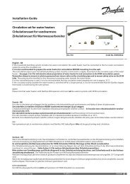
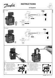
Application <strong>A375</strong>.2 / <strong>A375</strong>.3 (burner steps 7–8)<br />
Double-insulated (two-chamber) transformer<br />
Terminal Description Max. load<br />
5 Phase for control of burner steps 7 and 8<br />
4 Connection for motorized control valve - opening, circuit 2 (<strong>A375</strong>.3) 1 A / 24 V a.c.<br />
3 Connection for motorized control valve - closing, circuit 2 (<strong>A375</strong>.3) 1 A / 24 V a.c.<br />
2 K7 Auxilliary relay for control of burner step 7 1 A / 24 V a.c.<br />
1 K8 Auxilliary relay for control of burner step 8 1 A / 24 V a.c.<br />
Do not connect 230 V a.c. powered components to a 24 V a.c. power<br />
supplied controller directly. Use auxilliary relays (K) to separate 230<br />
V a.c. from 24 V a.c.<br />
Wire cross section: 0.5 - 1.5 mm²<br />
Incorrect connection can damage the electronic outputs.<br />
Max. 2 x 1.5 mm² wires can be inserted into each screw terminal.<br />
<strong>Danfoss</strong> District Energy VI.GU.L1.02 DEN-SMT/DK 69