ECL Comfort 210/310, A275/A375 Installation Guide - Danfoss ...
ECL Comfort 210/310, A275/A375 Installation Guide - Danfoss ...
ECL Comfort 210/310, A275/A375 Installation Guide - Danfoss ...

Create successful ePaper yourself
Turn your PDF publications into a flip-book with our unique Google optimized e-Paper software.
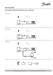
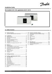
<strong>Installation</strong> <strong>Guide</strong> <strong>ECL</strong> <strong>Comfort</strong> <strong>210</strong> / <strong>310</strong>, application <strong>A275</strong> / <strong>A375</strong><br />
8.8.9 Communication<br />
Modbus addr. 38<br />
Circuit Setting range Factory setting<br />
1 ... 247 1<br />
Set the Modbus address if the controller is part of a Modbus network.<br />
1 ... 247: Assign the Modbus address within the stated setting<br />
range.<br />
<strong>ECL</strong> 485 addr. (master / slave address) 2048<br />
Circuit Setting range Factory setting<br />
0 ... 15 15<br />
This settting is relevant if more controllers are working in the same <strong>ECL</strong><br />
<strong>Comfort</strong> system (connected via the <strong>ECL</strong> 485 communication bus) and / or<br />
Remote Control Units (ECA 30 / 31) are connected.<br />
0: The controller works as slave.<br />
The slave receives information about the outdoor<br />
temperature (S1), system time, and signal for DHW<br />
demand in the master.<br />
1 ... 9: The controller works as slave.<br />
The slave receives information about the outdoor<br />
temperature (S1), system time, and signal for DHW<br />
demand in the master. The slave sends information<br />
about the desired flow temperature to the master.<br />
10 ... 14: Reserved.<br />
15: The <strong>ECL</strong> 485 communication bus is active.<br />
The controller is master. The master sends information<br />
about the outdoor temperature (S1) and system time.<br />
Connected Remote Control Units (ECA 30 / 31) are<br />
powered.<br />
The <strong>ECL</strong> <strong>Comfort</strong> controllers can be connected via the <strong>ECL</strong> 485<br />
communication bus to perform a larger system (the <strong>ECL</strong> 485<br />
communication bus can connect to max. 16 devices).<br />
Each slave must be configured with its own address (1 ... 9).<br />
However, more slaves can have the address 0 if they only have to<br />
receive information about outdoor temperature and system time<br />
(listeners).<br />
Service Pin 2150<br />
Circuit Setting range Factory setting<br />
This setting is only used in connection with set-up of Modbus<br />
communication.<br />
0: Service pin not activated.<br />
1: Activation of service pin.<br />
0 / 1 0<br />
The total cable length of max. 200 m (all devices incl. the internal <strong>ECL</strong><br />
485 communication bus) should not be exceeded.<br />
Cable lengths of more than 200 m may cause noise sensibility (EMC).<br />
<strong>Danfoss</strong> District Energy VI.GU.L1.02 DEN-SMT/DK 165