Power Planer Original Instruction Manual Електричний ... - Makita
Power Planer Original Instruction Manual Електричний ... - Makita
Power Planer Original Instruction Manual Електричний ... - Makita

You also want an ePaper? Increase the reach of your titles
YUMPU automatically turns print PDFs into web optimized ePapers that Google loves.
ENGLISH (<strong>Original</strong> instructions)<br />
1-1. Knob<br />
2-1. Switch trigger<br />
3-1. Lock button / Lock-off button<br />
3-2. Switch trigger<br />
4-1. Socket wrench<br />
4-2. Bolt<br />
5-1. Bolt<br />
5-2. Drum<br />
5-3. <strong>Planer</strong> blade<br />
5-4. Drum cover<br />
5-5. Adjusting plate<br />
6-1. Inside edge of gauge plate<br />
6-2. Blade edge<br />
6-3. <strong>Planer</strong> blade<br />
6-4. Adjusting plate<br />
6-5. Screws<br />
6-6. Heel<br />
6-7. Back side of gauge base<br />
6-8. Gauge plate<br />
6-9. Gauge base<br />
7-1. Socket wrench<br />
7-2. Bolt<br />
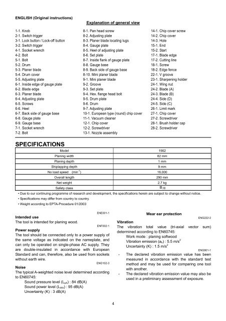
SPECIFICATIONS<br />
Explanation of general view<br />
8-1. Pan head screw<br />
8-2. Adjusting plate<br />
8-3. <strong>Planer</strong> blade locating lugs<br />
8-4. Gauge plate<br />
8-5. Heel of adjusting plate<br />
8-6. Set plate<br />
8-7. Inside flank of gauge plate<br />
8-8. Gauge base<br />
8-9. Back side of gauge base<br />
8-10. Mini planer blade<br />
9-1. Mini planer blade<br />
9-2. Groove<br />
9-3. Set plate<br />
9-4. Hex. flange head bolt<br />
9-5. Drum plate<br />
9-6. Drum<br />
9-7. Adjusting plate<br />
10-1. European type (round) chip cover<br />
11-1. Vacuum cleaner<br />
12-1. Chip cover<br />
12-2. Screwdriver<br />
13-1. Nozzle assembly<br />
4<br />
14-1. Chip cover screw<br />
14-2. Chip cover<br />
14-3. Hole<br />
15-1. End<br />
15-2. Start<br />
17-1. Blade edge<br />
17-2. Cutting line<br />
18-1. Screw<br />
18-2. Edge fence<br />
22-1. V groove<br />
23-1. Sharpening holder<br />
24-1. Wing nut<br />
24-2. Blade (A)<br />
24-3. Blade (B)<br />
24-4. Side (D)<br />
24-5. Side (C)<br />
26-1. Limit mark<br />
27-1. Chip cover<br />
27-2. Screwdriver<br />
28-1. Brush holder cap<br />
28-2. Screwdriver<br />
Model 1902<br />
Planing width 82 mm<br />
Planing depth 1 mm<br />
Shiplapping depth 9 mm<br />
No load speed (min -1 ) 16,000<br />
Overall length 290 mm<br />
Net weight 2.7 kg<br />
Safety class /II<br />
• Due to our continuing programme of research and development, the specifications herein are subject to change without notice.<br />
• Specifications may differ from country to country.<br />
• Weight according to EPTA-Procedure 01/2003<br />
Intended use<br />
The tool is intended for planing wood.<br />
ENE001-1<br />
ENF002-1<br />
<strong>Power</strong> supply<br />
The tool should be connected only to a power supply of<br />
the same voltage as indicated on the nameplate, and<br />
can only be operated on single-phase AC supply. They<br />
are double-insulated in accordance with European<br />
Standard and can, therefore, also be used from sockets<br />
without earth wire.<br />
ENG102-3<br />
Noise<br />
The typical A-weighted noise level determined according<br />
to EN60745:<br />
Sound pressure level (LpA) : 84 dB(A)<br />
Sound power level (LWA) : 95 dB(A)<br />
Uncertainty (K) : 3 dB(A)<br />
Wear ear protection<br />
ENG222-2<br />
Vibration<br />
The vibration total value (tri-axial vector sum)<br />
determined according to EN60745:<br />
Work mode : planing softwood<br />
Vibration emission (ah) : 5.5 m/s 2<br />
Uncertainty (K) : 1.5 m/s 2<br />
•<br />
ENG901-1<br />
The declared vibration emission value has been<br />
measured in accordance with the standard test<br />
method and may be used for comparing one tool<br />
with another.<br />
• The declared vibration emission value may also be<br />
used in a preliminary assessment of exposure.