M12 Oncore Users Guide Supplement - deetc - isel
M12 Oncore Users Guide Supplement - deetc - isel
M12 Oncore Users Guide Supplement - deetc - isel

Create successful ePaper yourself
Turn your PDF publications into a flip-book with our unique Google optimized e-Paper software.
<strong>M12</strong> User’s <strong>Guide</strong><br />
<strong>Supplement</strong>
<strong>M12</strong> <strong>Oncore</strong><br />
User’s <strong>Guide</strong> <strong>Supplement</strong><br />
1. Product Specifications<br />
2. Basic Description<br />
3. Mechanical<br />
4. Environmental<br />
5. Electrical<br />
6. RF Characteristics of Receiver<br />
7. RF Requirements for Antenna<br />
8. Performance<br />
9. Features<br />
10. Serial I/O Messages<br />
11. Receiver/Controller Command Descriptions<br />
Motorola GPS Products<br />
<strong>M12</strong> <strong>Oncore</strong> User’s <strong>Guide</strong> <strong>Supplement</strong><br />
Revision 1.0 01/25/00<br />
2
General<br />
Characteristics<br />
Performance<br />
Characteristics<br />
Serial<br />
Communication<br />
Electrical<br />
Characteristics<br />
Environmental<br />
Characteristics<br />
Miscellaneous<br />
Motorola GPS Products<br />
<strong>M12</strong> <strong>Oncore</strong> User’s <strong>Guide</strong> <strong>Supplement</strong><br />
Revision 1.0 01/25/00<br />
Receiver Architecture • 12 parallel channels<br />
• L1 1575.42 MHz<br />
• C/A code (1.023 MHz chip rate)<br />
• Code plus carrier tracking (carrier aided tracking)<br />
Tracking Capability • 12 simultaneous satellites<br />
Dynamics • Velocity: 515 m/s (1000 knots); >515 m/s at altitudes < 18,000 m<br />
• Acceleration: 4 g<br />
• Jerk: 5 m/s 3<br />
• Vibration: 7.7G per Military Standard 810E<br />
Acquisition Time •
2. Basic Description<br />
2.1 Receiver architecture<br />
Channels 12 parallel<br />
Frequency 1575.42 MHz<br />
Code C/A<br />
Tracking Carrier aided<br />
2.2 Description<br />
The highly integrated single board GPS receiver module is optimized specifically for automotive<br />
applications. The GPS receiver tracks the NAVSTAR GPS constellation of satellites. The satellite<br />
signals received by an active antenna are tracked with 12 parallel channels of L1, C/A code then<br />
downconverted to an IF frequency and digitally processed to obtain a full navigation solution of<br />
position, velocity, time and heading. The solution is then sent over the serial link via the 10-pin<br />
connector.<br />
Motorola GPS Products<br />
<strong>M12</strong> <strong>Oncore</strong> User’s <strong>Guide</strong> <strong>Supplement</strong><br />
Revision 1.0 01/25/00<br />
4
3. Mechanical<br />
3.1 Mechanical Drawings<br />
3.1.1 <strong>M12</strong> <strong>Oncore</strong> with right angle power/data connector<br />
3.1.2 <strong>M12</strong> <strong>Oncore</strong> with straight power/data connector<br />
Motorola GPS Products<br />
<strong>M12</strong> <strong>Oncore</strong> User’s <strong>Guide</strong> <strong>Supplement</strong><br />
Revision 1.0 01/25/00<br />
5
3.2 Size<br />
Motorola GPS Products<br />
<strong>M12</strong> <strong>Oncore</strong> User’s <strong>Guide</strong> <strong>Supplement</strong><br />
Revision 1.0 01/25/00<br />
Dimensions 40.0 x 60.0 x 10.0 mm<br />
3.3 Weight < 25 g<br />
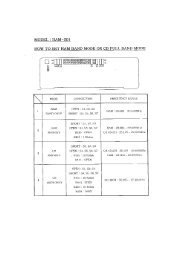
3.4 Connectors<br />
4. Environmental<br />
Power/Data Straight: Samtec, FW-05-03-L-D-156-156, 10-pin<br />
Right Angle: Samtec, ASP62522-01-M, 10-pin<br />
Antenna RF Sub-miniature MMCX connector type<br />
4.1 Temperature<br />
Operating -40°C to +85°C<br />
Storage -40°C to +105°C<br />
4.2 Relative humidity<br />
Operating 95% over dry bulb range of +38°C to +85°C<br />
4.3 Vibration 0.04 G 2 /Hz, 20 Hz to 1000 Hz<br />
5. Electrical<br />
5.1 Pin Outputs<br />
7.7 G per Military Standard 810E<br />
Pin # Signal Description<br />
1 TTL TXD1 Transmit 3 V logic<br />
2 TTL RXD1 Receive 3 V logic<br />
3 +3.0 V PWR +3 V regulated main power<br />
4 1 PPS One pulse per second signal<br />
5 GROUND Ground (receiver)<br />
6 BATTERY Externally applied backup power (1.8 to 3.2 V)<br />
7 Reserved Not currently used<br />
8 RTCM IN RTCM input only<br />
9 ANTENNA VOLTAGE 3 V or 5 V antenna input voltage<br />
10 Reserved Not currently used<br />
6
5.2 Main power<br />
Motorola GPS Products<br />
<strong>M12</strong> <strong>Oncore</strong> User’s <strong>Guide</strong> <strong>Supplement</strong><br />
Revision 1.0 01/25/00<br />
Voltage 2.8 to 3.2 Vdc regulated<br />
50 mV maximum peak-to-peak ripple<br />
Power 0.225 W maximum (without antenna)<br />
5.3 Backup power<br />
Voltage 1.8 V to 3.2 V<br />
Current 5 mA typical @ 2.7 V<br />
Retention Backup power retains date, time, position, satellite data,<br />
oscillator learning table and operating mode<br />
5.4 Antenna feed power out of RF connector<br />
Voltage 2.7 V to 3.2 V over current range for 3 V antenna<br />
Current 15 mA to 80 mA<br />
5.5 1PPS signal definition<br />
Level 0 V to 3 V<br />
Time mark Rising edge<br />
Width 200 ms typical<br />
5.6 Serial I/O signal definition<br />
Levels 0 V to 3 V, active low<br />
Flags set in serial data when limits exceeded<br />
Baud rate 9600 (Motorola Binary)<br />
Parity None<br />
Data bits 8<br />
Start/stop bits 1<br />
6. RF Characteristics of Receiver<br />
6.1 Dynamic range 27 dB<br />
4800 (NMEA)<br />
6.2 Saturation -110 dBm<br />
7
7. RF Requirements for Antenna<br />
7.1 General<br />
Motorola GPS Products<br />
<strong>M12</strong> <strong>Oncore</strong> User’s <strong>Guide</strong> <strong>Supplement</strong><br />
Revision 1.0 01/25/00<br />
Frequency 1575.42 MHz (L1)<br />
Bandwidth ± 1.023 MHz<br />
Polarization Right hand circular<br />
Impedance 50 Ω<br />
7.2 Gain requirement 16 dB to 30 dB (at receiver input)<br />
7.3 Gain Pattern +0 dBic minimum at zenith<br />
7.4 Noise figure 1.8 dB typical<br />
-10 dBic minimum at 0° elevation<br />
2.2 dB maximum<br />
7.5 VSWR 1.5:1 typical<br />
2.5:1 maximum<br />
7.6 Axial ratio 3 dB typical at zenith<br />
6 dB maximum at zenith<br />
7.7 1 dB compression point -14 dBm typical (at antenna output)<br />
7.8 3 dB frequency bandwidth 45 MHz maximum<br />
7.9 25 dB frequency rejection ± 95 MHz<br />
7.10 Ground plane 15 x 15 cm recommended<br />
7.11 Power<br />
Voltage 2.8 V to 3.2 V, or 4.75 V to 5.25 V<br />
Current 15 mA typical<br />
7.12 Temperature<br />
3.0 V typical, or 5.0 V typical<br />
25 mA maximum<br />
Operating -40°C to +85°C<br />
Storage -40°C to +100°C<br />
8
8. Performance<br />
8.1 Accuracy<br />
Motorola GPS Products<br />
<strong>M12</strong> <strong>Oncore</strong> User’s <strong>Guide</strong> <strong>Supplement</strong><br />
Revision 1.0 01/25/00<br />
Position 25 m SEP without SA<br />
100 m 2DRMS (95%) with SA<br />
1 to 5 m typical in differential mode<br />
Altitude 156 m RMS (95%)<br />
Velocity 0.02 m/s without SA<br />
Time pulse UTC ± 500 ns with SA on<br />
8.2 Dynamic limits<br />
Velocity 515 m/s maximum at altitudes > 18000 m<br />
Altitude -1000 m minimum<br />
Acceleration 4 G maximum<br />
Jerk 5 m/s 3 maximum<br />
8.3 Startup time (TTFF)<br />
Hot (date, time, position, almanac, ephemeris) 15 s<br />
Warm (date, time, position, almanac, olt) 45 s<br />
Cold (no stored information) 70 s<br />
8.4 Reacquisition time<br />
8.5 RFI<br />
8.6 EMI<br />
After 60 s obstruction 3.5 s<br />
Internal < 1.0 s<br />
18000 m maximum at velocities > 515 m/s<br />
Jamming resistance Resistant to narrow band CW jamming at the<br />
receiver input of +20dBm at less than 1525<br />
MHz and greater than 1625 MHz for loss of<br />
lock with a signal input of –130 dBm<br />
Burnout protection Protected from damage by RF signals at<br />
frequencies100 MHz or more from L1 with<br />
received power up to 1 W at the antenna<br />
Radiated Complies with Class B, Part 15 of FCC rules<br />
Conducted Complies with European CE requirements<br />
Tested to IEC 801-4 spec for fast transients<br />
at 500 V, 5/50 ns, 5 kHz<br />
9
9. Features<br />
9.1 Differential operation<br />
Motorola GPS Products<br />
<strong>M12</strong> <strong>Oncore</strong> User’s <strong>Guide</strong> <strong>Supplement</strong><br />
Revision 1.0 01/25/00<br />
Motorola binary corrections on TTL RXD1 (pin 2) at 9600 baud<br />
RTCM SC-104 Type 1 and Type 9 corrections on TTL RXD2 (pin 8) at 2400 or 9600 baud<br />
9.2 NMEA 0183 output<br />
NMEA 0183 Output on TTL TX1 at 4800 baud<br />
Messages supported GGA, GLL, GSA, GSV, RMC, VTG, ZDA<br />
9.3 User definable datum<br />
One user definable datum may be defined using the @@Ap command. The default datum is<br />
WGS-84.<br />
9.4 Antenna sense circuit<br />
The <strong>M12</strong> <strong>Oncore</strong> receiver is capable of detecting the presence of an antenna. The receiver<br />
utilizes an antenna sense circuit, which can detect under current (open) and over current<br />
(shorted or exceeding maximum limit) conditions. The status of the antenna circuit is<br />
reported in the Position/Status/Data Message (@@Ha), the Short Position Message (@@Hb)<br />
and the Self-Test Message (@@Ia).<br />
The antenna sense circuit is useful for verifying that the antenna is properly connected to the<br />
receiver and is drawing the proper amount of current. The antenna sense status should be<br />
checked after installation and monitored regularly.<br />
9.5 Real time clock<br />
Undercurrent indication < 8 mA<br />
Overcurrent indication > 80 mA<br />
The real-time clock (RTC) is a standard feature on the <strong>M12</strong> <strong>Oncore</strong>. It is used to minimize<br />
the time to first fix (TTFF). The date and time will be retained in the RTC if battery backup<br />
power is applied when main power is off.<br />
The user has two options regarding time initialization:<br />
1) Set the date and time BEFORE the receiver acquires any satellites<br />
2) Let the receiver automatically set the date and time AFTER acquiring the first satellite<br />
Note: The date and time cannot be manually set while the receiver is tracking satellites.<br />
Without battery backup, the receiver will start-up with a default time of 12:00:00. To obtain a<br />
faster time to first fix, the time, date and GMT offset should be initialized if both the main<br />
power and battery backup power have been disconnected.<br />
10
10. Serial I/O Messages<br />
10.1 Solution<br />
Motorola GPS Products<br />
<strong>M12</strong> <strong>Oncore</strong> User’s <strong>Guide</strong> <strong>Supplement</strong><br />
Revision 1.0 01/25/00<br />
Update rate 1 Hz maximum (Selectable 1/s – 1/255s)<br />
Latency < 1 s<br />
Reported Position, velocity, time, satellite status, receiver status,<br />
antenna status<br />
Reference WGS-84 or user defined datum<br />
10.2 Resolution<br />
Latitude/longitude 1 milliarcsecond<br />
Height 0.01 m<br />
Velocity 0.01 m/s<br />
Heading 0.1°<br />
Time 1 ns<br />
10.3 Solution quality indicators<br />
Receiver status 3D, 2D, propagation, acquisition<br />
Geometry HDOP when in 2D mode<br />
Satellite status C/No (dB)<br />
10.4 Initialization<br />
PDOP when in 3D mode<br />
Flag indicating satellite tracking status<br />
Flag indicating satellite is used in solution<br />
Startup mode Acquisition based on information available<br />
Battery backup provided No initialization required<br />
No battery backup Receiver will be in default condition, entering date, time,<br />
position and almanac will speed up acquisition process<br />
Default condition No serial messages active unless there is a power-on selftest<br />
failure<br />
10.5 RTCM Commands<br />
The <strong>M12</strong> <strong>Oncore</strong> accepts RTCM SC-104 Type 1 and Type 9 messages. The messages are<br />
input on the second communications port (pin 8) at a user selectable baud rate of 2400,<br />
4800 or 9600. The RTCM messages are buffered and processed independently from the<br />
primary communications port.<br />
11
10.6 Motorola binary I/O command list<br />
Motorola binary commands can be used to initialize, configure, control and monitor the GPS receiver.<br />
The Motorola binary commands are supported on the primary communications port at 9600 baud.<br />
The commands supported by the <strong>M12</strong> <strong>Oncore</strong> are listed in the table below, and detailed command<br />
descriptions are provided in alphabetical order by binary command on subsequent pages.<br />
Function Description Binary Controller <strong>Supplement</strong><br />
Command Command Page #<br />
Satellite Set Mask Angle @@Ag mask 14<br />
Receiver Satellite Ignore List @@Am ignore 16<br />
Setup Select Datum @@Ao datum 18<br />
Setup Set User Datum @@Ap udatum 20<br />
Setup Atmospheric Correction Mode @@Aq ion 22<br />
1PPS Position-Hold Position @@As php 24<br />
Setup Altitude-Hold Height @@Au ahp 26<br />
Time Time Mode @@Aw utc 28<br />
1PPS 1PPS Cable Delay @@Az ppsdelay 30<br />
Position Position Lock Parameters @@AM lockp 32<br />
Setup Velocity Filter @@AN filter 34<br />
Setup RTCM Port Mode @@AO p2baud 36<br />
Position Position Filter Select @@AQ pfilter 38<br />
Position Position Lock Select @@AS locke 40<br />
Satellite Visible Satellite Status @@Bb vis 42<br />
Almanac Almanac Status @@Bd alm 44<br />
Almanac Almanac Data Output @@Be almout 46<br />
Ephemeris Ephemeris Data Input @@Bf ephin 48<br />
Almanac Almanac Data Input @@Cb almin 50<br />
Time UTC Offset Status @@Bo utcoff 52<br />
Receiver UTC/Ionospheric Data Output @@Bp utcion 54<br />
DGPS Pseudorange Correction Input @@Ce n/a 56<br />
Receiver Set-to-Defaults @@Cf default 58<br />
NMEA Switch to NMEA @@Ci ioformat 60<br />
Receiver Receiver ID @@Cj id 62<br />
Receiver UTC/Ionospheric Data Input @@Co n/a 64<br />
Position ASCII Position Message @@Eq as8 66<br />
Position Combined Position @@Ga compo 68<br />
Time Combined Time @@Gb comtim 70<br />
1PPS 1PPS Control @@Gc ppscon 72<br />
Position Position Control @@Gd holdcon 74<br />
Time Leap Second Status @@Gj leap12 76<br />
Setup ID Tag @@Gk vin 78<br />
Position Position/Status/Data Message (12Ch) @@Ha ps12 80<br />
Position Short Position Message (12Ch) @@Hb psd 86<br />
Setup Self-Test Message (12Ch) @@Ia selftest12 90<br />
Receiver System Power-On Failure @@Sz n/a 92<br />
NMEA NMEA Messages n/a n/a 94-109<br />
Motorola GPS Products<br />
<strong>M12</strong> <strong>Oncore</strong> User’s <strong>Guide</strong> <strong>Supplement</strong><br />
Revision 1.0 01/25/00<br />
12
Motorola GPS Products<br />
<strong>M12</strong> <strong>Oncore</strong> User’s <strong>Guide</strong> <strong>Supplement</strong><br />
Revision 1.0 01/25/00<br />
Page intentionally left blank.<br />
13
Motorola GPS Products<br />
<strong>M12</strong> <strong>Oncore</strong> User’s <strong>Guide</strong> <strong>Supplement</strong><br />
Revision 1.0 01/25/00<br />
SATELLITE MASK ANGLE<br />
The GPS receiver will attempt to track satellites for which the elevation angle is<br />
greater than the satellite mask angle. This parameter allows the user to control the<br />
elevation angle that was used for this decision.<br />
Range: 0 to 89 degrees<br />
Default value: 0 degrees<br />
14
Input Command<br />
Response Message<br />
Motorola GPS Products<br />
<strong>M12</strong> <strong>Oncore</strong> User’s <strong>Guide</strong> <strong>Supplement</strong><br />
Revision 1.0 01/25/00<br />
SATELLITE MASK ANGLE<br />
Motorola Binary Format<br />
• Poll current mask angle:<br />
@@AgxC<br />
x 1 out of range byte $ff<br />
C checksum<br />
Message length: 8 bytes<br />
• Change current mask angle:<br />
@@AgdC<br />
d degrees 0 .. 89<br />
C checksum<br />
Message length: 8 bytes<br />
• To either command:<br />
@@AgdC<br />
d degrees 0 .. 89<br />
C checksum<br />
Message length: 8 bytes<br />
15
Motorola GPS Products<br />
<strong>M12</strong> <strong>Oncore</strong> User’s <strong>Guide</strong> <strong>Supplement</strong><br />
Revision 1.0 01/25/00<br />
SATELLITE IGNORE LIST<br />
It is useful to have the flexibility to delete particular satellite identification numbers<br />
(SVIDs) from the selection process. The GPS receiver includes, in its list of satellites<br />
to track, all satellites that are healthy and in the almanac. The user can elect to<br />
ignore particular satellites in the almanac by issuing an Ignore Satellite Command.<br />
In addition, the user can restore any previously ignored satellite IDs by issuing an<br />
Include Satellite Command. This command also affects the satellite Alert-Planning<br />
settings. Satellites that have been removed by this command are not included in the<br />
produced Alert-Planning output. The user may notice a delay between issuing this<br />
command and the actual removal or inclusion of particular satellites.<br />
Default value: All satellite SVIDs included.<br />
16
Input Command SATELLITE IGNORE LIST<br />
Motorola Binary Format<br />
Response Message<br />
Motorola GPS Products<br />
<strong>M12</strong> <strong>Oncore</strong> User’s <strong>Guide</strong> <strong>Supplement</strong><br />
Revision 1.0 01/25/00<br />
• Send Current Satellite Ignore List:<br />
@@AmxxxxxC<br />
xxxxx 5 bytes all hex 00<br />
C checksum<br />
Message Length: 12 bytes<br />
• Change Satellite Ignore List:<br />
@@AmkssssC<br />
k 00 fixed binary constant<br />
ssss 32 bit binary field. Each bit represents one SVID.<br />
(msb = SVID 32, lsb = SVID 1)<br />
1 = Ignore<br />
0 = Include<br />
C checksum<br />
Message Length: 12 bytes<br />
• To either command:<br />
@@AmkssssC<br />
k 00 fixed binary constant<br />
ssss 32 bit binary field. Each bit represents one SVID.<br />
(msb = SVID 32, lsb = SVID 1)<br />
1 = Ignore<br />
0 = Include<br />
C checksum<br />
Message Length: 12 bytes<br />
17
Motorola GPS Products<br />
<strong>M12</strong> <strong>Oncore</strong> User’s <strong>Guide</strong> <strong>Supplement</strong><br />
Revision 1.0 01/25/00<br />
SELECT DATUM<br />
The GPS receiver has one predefined datum in its internal memory and one user<br />
definable datum. The datums are referenced by an ID number. The predefined<br />
datum is number 49 and the user defined datum is number 50. The user instructs<br />
the GPS receiver which datum to use by sending the Select Datum command. The<br />
command contains the ID number of the desired datum and the GPS receiver<br />
returns the response message which gives the user the ability to validate that the<br />
input command was accepted. The user can instruct the GPS receiver to use the<br />
user defined datum by sending the Select Datum command set to 50.<br />
Default datum: WGS-84 (ID code 49)<br />
18
Input Command<br />
Response Message<br />
Motorola GPS Products<br />
<strong>M12</strong> <strong>Oncore</strong> User’s <strong>Guide</strong> <strong>Supplement</strong><br />
Revision 1.0 01/25/00<br />
SELECT DATUM<br />
Motorola Binary Format<br />
• Poll current datum ID code:<br />
@@AoxC<br />
x 1 out of range byte $ff<br />
C checksum<br />
Message length: 8 bytes<br />
• Change current datum ID code:<br />
@@AodC<br />
d datum ID 49 or 50<br />
C checksum<br />
Message length: 8 bytes<br />
• To either command:<br />
@@ApdsssffiiffffxxyyzzC<br />
d datum ID 49 or 50<br />
sssff semi-major axis (m)<br />
sss integer part 6,000,000 .. 7,000,000<br />
ff fractional part 0 .. 999 (0.0 .. 0.999)<br />
iiffff inverse flattening<br />
ii integer part 285 .. 305<br />
ffff fractional part 0 .. 999,999,999 (0.0 .. 0.999999999)<br />
xx delta X (0.1 m) -32,768 .. 32,767 (-3276.8 .. 3276.7)<br />
yy delta Y (0.1 m) -32,768 .. 32,767 (-3276.8 .. 3276.7)<br />
zz delta Z (0.1 m) -32,768 .. 32,767 (-3276.8 .. 3276.7)<br />
C checksum<br />
Message length: 25 bytes<br />
19
Motorola GPS Products<br />
<strong>M12</strong> <strong>Oncore</strong> User’s <strong>Guide</strong> <strong>Supplement</strong><br />
Revision 1.0 01/25/00<br />
SET USER DATUM<br />
The GPS receiver has one user defined datum stored as ID number 50. The User<br />
Datum command allows the user to define the constants used for a custom datum.<br />
A datum is defined by a semi-major axis, an inverse flattening constant, and an<br />
offset from the center of mass of the earth given as delta-X, delta-Y, and delta-Z<br />
parameters.<br />
Default values: WGS-84 parameters<br />
20
Input Command<br />
Response Message<br />
Motorola GPS Products<br />
<strong>M12</strong> <strong>Oncore</strong> User’s <strong>Guide</strong> <strong>Supplement</strong><br />
Revision 1.0 01/25/00<br />
SET USER DATUM<br />
Motorola Binary Format<br />
• Poll current user defined datum parameters:<br />
@@ApdxxxxxxxxxxxxxxxxxC<br />
d desired user datum 50<br />
xxxxxxxxxxxxxxxxx 17 bytes all hex 00<br />
C<br />
Message length: 25 bytes<br />
checksum<br />
• Change current user defined datum parameters:<br />
@@ApdsssffiiffffxxyyzzC<br />
d datum ID 50<br />
sssff semi-major axis (m)<br />
sss integer part 6,000,000 .. 7,000,000<br />
ff fractional part 0 .. 999 (0.0 .. 0.999)<br />
iiffff inverse flattening<br />
ii integer part 285 .. 305<br />
ffff fractional part 0 .. 999,999,999 (0.0 .. 0.999999999)<br />
xx delta X (0.1 m) -32,768 .. 32,767 (-3276.8 .. 3276.7)<br />
yy delta Y (0.1 m) -32,768 .. 32,767 (-3276.8 .. 3276.7)<br />
zz delta Z (0.1 m) -32,768 .. 32,767 (-3276.8 .. 3276.7)<br />
C checksum<br />
Message length: 25 bytes<br />
• To either command:<br />
@@ApdsssffiiffffxxyyzzC<br />
d datum ID 50<br />
sssff semi-major axis (m)<br />
sss integer part 6,000,000 .. 7,000,000<br />
ff fractional part 0 .. 999 (0.0 .. 0.999)<br />
iiffff inverse flattening<br />
ii integer part 285 .. 305<br />
ffff fractional part 0 .. 999,999,999 (0.0 .. 0.999999999)<br />
xx delta X (0.1 m) -32,768 .. 32,767 (-3276.8 .. 3276.7)<br />
yy delta Y (0.1 m) -32,768 .. 32,767 (-3276.8 .. 3276.7)<br />
zz delta Z (0.1 m) -32,768 .. 32,767 (-3276.8 .. 3276.7)<br />
C checksum<br />
Message length: 25 bytes<br />
21
Motorola GPS Products<br />
<strong>M12</strong> <strong>Oncore</strong> User’s <strong>Guide</strong> <strong>Supplement</strong><br />
Revision 1.0 01/25/00<br />
ATMOSPHERIC CORRECTION MODE<br />
The user has the flexibility of turning the GPS ionospheric and/or tropospheric<br />
correction models on or off. The models do a reasonable job of taking out the range<br />
error induced by the earth’s ionosphere and troposphere by using algorithms and<br />
parameters transmitted to the users by the satellites. For some applications, such as<br />
differential systems, the atmospheric models should be disabled since the differential<br />
corrections include the atmospheric errors.<br />
Default modes: Ionospheric model enabled<br />
Tropospheric model disabled<br />
22
Input Command<br />
Response Message<br />
Motorola GPS Products<br />
<strong>M12</strong> <strong>Oncore</strong> User’s <strong>Guide</strong> <strong>Supplement</strong><br />
Revision 1.0 01/25/00<br />
ATMOSPHERIC CORRECTION MODE<br />
Motorola Binary Format<br />
• Poll current Atmospheric Correction Mode:<br />
@@AqxC<br />
x 1 out of range byte $ff<br />
C checksum<br />
Message length: 8 bytes<br />
• Change current Atmospheric Correction Mode:<br />
@@AqsC<br />
s selection 0 = both models disabled<br />
1 = ionospheric model only enabled<br />
2 = tropospheric model only enabled<br />
3 = both models enabled<br />
C checksum<br />
Message length: 8 bytes<br />
• To either command:<br />
@@AqsC<br />
s selection 0 = both models disabled<br />
1 = ionospheric model only enabled<br />
2 = tropospheric model only enabled<br />
3 = both models enabled<br />
C checksum<br />
Message length: 8 bytes<br />
23
Motorola GPS Products<br />
<strong>M12</strong> <strong>Oncore</strong> User’s <strong>Guide</strong> <strong>Supplement</strong><br />
Revision 1.0 01/25/00<br />
POSITION-HOLD POSITION<br />
The user can specify receiver coordinates for timing applications to increase the<br />
timing accuracy. This command is used to enter the position to be held. Note that<br />
this command will only be executed if the Position Control (@@Gd) position hold is<br />
disabled.<br />
The position to be held is specified in the same units and referenced to the same<br />
datum (WGS 84) as the initial position coordinates of latitude, longitude and height<br />
(to the same resolution). The height parameter is referenced to the GPS reference<br />
ellipsoid. Note that all three parameters must be specified. The valid ranges of each<br />
parameter are the same as those specified in the Combined Position Message<br />
(@@Ga).<br />
Default values: Latitude = 0° (Equator)<br />
Longitude = 0° (Grenwich Meridian)<br />
Height = 0 m (GPS Height)<br />
24
Input Command POSITION-HOLD POSITION<br />
Motorola Binary Format<br />
Response Message<br />
Motorola GPS Products<br />
<strong>M12</strong> <strong>Oncore</strong> User’s <strong>Guide</strong> <strong>Supplement</strong><br />
Revision 1.0 01/25/00<br />
• Poll current Position-Hold Position:<br />
@@AsxxxxxxxxxxxxxC<br />
xxxxxxxxxxxx 13 out of range bytes $7fffffff7fffffff7fffffffff<br />
C checksum<br />
Message length: 20 bytes<br />
• Change current Position-Hold Position:<br />
@@AslllloooohhhhtC<br />
llll latitude in mas -324,000,000 .. 324,000,000 (-90° .. 90°)<br />
oooo longitude in mas -648,000,000 .. 648,000,000 (-180° .. 180°)<br />
hhhh height in cm -100000 .. 1,800,000 (-1,000.00 .. 18,000.00 m)<br />
t height type 0 = GPS height<br />
C checksum<br />
Message length: 20 bytes<br />
• To either command:<br />
@@AslllloooohhhhtC<br />
llll latitude in mas -324,000,000 .. 324,000,000 (-90° .. 90°)<br />
oooo longitude in mas -648,000,000 .. 648,000,000 (-180° ..180°)<br />
hhhh height in cm -100,000 .. 1,800,000 (-1,000.00 .. 18,000.00 m)<br />
t height type 0 = GPS height<br />
C checksum<br />
Message length: 20 bytes<br />
NOTE: Position-Hold Position is enabled and disabled using the Position Control command<br />
(@@Gd).<br />
25
Motorola GPS Products<br />
<strong>M12</strong> <strong>Oncore</strong> User’s <strong>Guide</strong> <strong>Supplement</strong><br />
Revision 1.0 01/25/00<br />
ALTITUDE-HOLD HEIGHT<br />
The user can specify the receiver height for manual altitude-hold applications. Use<br />
the Position Control (@@Gd) command to enable or disable the altitude-hold<br />
feature. The Altitude-Hold Height is specified in units of meters to a resolution of<br />
0.01 meters. The height is referenced to the GPS reference ellipsoid. The datum for<br />
the height is the one selected using the Select Datum command.<br />
Default value: 0 m<br />
26
Input Command<br />
Response Message<br />
Motorola GPS Products<br />
<strong>M12</strong> <strong>Oncore</strong> User’s <strong>Guide</strong> <strong>Supplement</strong><br />
Revision 1.0 01/25/00<br />
ALTITUDE-HOLD HEIGHT<br />
Motorola Binary Format<br />
• Poll current Altitude-Hold Height:<br />
@@AuxxxxxC<br />
xxxx 5 out of range bytes $7ffffffff<br />
C checksum<br />
Message length: 12 bytes<br />
• Change current Altitude-Hold Height:<br />
@@AuhhhhtC<br />
hhhh height in cm -100,000 .. 1,800,000 (-1000.00 to + 18,000.00 m)<br />
t height type 0 = GPS height<br />
C checksum<br />
Message length: 12 bytes<br />
• To either command:<br />
@@AuhhhhtC<br />
hhhh height in cm -100,000 .. 1,800,000 (-1000.00 to + 18,000.00 m)<br />
t height type 0 = GPS height<br />
C checksum<br />
Message length: 12 bytes<br />
Note: Altitude-Hold Height is enable and disabled using the Position Control command<br />
(@@Gd).<br />
27
Motorola GPS Products<br />
<strong>M12</strong> <strong>Oncore</strong> User’s <strong>Guide</strong> <strong>Supplement</strong><br />
Revision 1.0 01/25/00<br />
TIME MODE<br />
This command selects the type of time (either GPS or UTC) to be output in the<br />
Position/Status/Data and Short Position Messages. The Time Mode command will be used to<br />
determine the synchronization point for the 1PPS timing pulse.<br />
Note that if the receiver does not have the UTC parameters portion of the almanac, UTC will<br />
be output as being equal to GPS time and a flag denoting the lack of UTC parameters will be<br />
set in the Position/Status/Data message (@@Ha).<br />
The receiver will have the UTC parameters once an almanac has been downloaded from the<br />
satellites.<br />
Default mode: UTC<br />
28
Input Command<br />
Response Message<br />
Motorola GPS Products<br />
<strong>M12</strong> <strong>Oncore</strong> User’s <strong>Guide</strong> <strong>Supplement</strong><br />
Revision 1.0 01/25/00<br />
TIME MODE<br />
Motorola Binary Format<br />
• Poll current Time Mode:<br />
@@AwxC<br />
x 1 out of range byte $ff<br />
C checksum<br />
Message length: 8 bytes<br />
• Change current Time Mode:<br />
@@AwmC<br />
m mode 0 = GPS<br />
1 = UTC<br />
C checksum<br />
Message length: 8 bytes<br />
• To either command:<br />
@@AwmC<br />
m mode 0 = GPS<br />
1 = UTC<br />
C checksum<br />
Message length: 8 bytes<br />
29
Motorola GPS Products<br />
<strong>M12</strong> <strong>Oncore</strong> User’s <strong>Guide</strong> <strong>Supplement</strong><br />
Revision 1.0 01/25/00<br />
1PPS CABLE DELAY<br />
The GPS receiver outputs a 1PPS signal, the rising edge of which is placed at the top<br />
of the GPS or UTC one second time mark epoch as specified by the Time Mode. The<br />
1PPS Cable Delay command allows the user to offset the 1PPS time mark in one<br />
nanosecond increments relative to the measurement epoch.<br />
This parameter instructs the GPS receiver to output the 1PPS output pulse earlier in<br />
time to compensate for antenna cable delay. Up to one millisecond of equivalent<br />
cable delay can be removed. Zero cable delay is set for a zero-length antenna cable.<br />
The user should consult a cable data book for the delay per foot for the particular<br />
antenna cable used in order to compute the total cable delay needed for a particular<br />
installation.<br />
This parameter also allows the user to adjust the position of the 1PPS to compensate<br />
for other system delays.<br />
Range: 0.000 to 0.000999999 s<br />
Default value: 0.000 s<br />
Resolution: 1 ns<br />
30
Input Command<br />
Response Message<br />
Motorola GPS Products<br />
<strong>M12</strong> <strong>Oncore</strong> User’s <strong>Guide</strong> <strong>Supplement</strong><br />
Revision 1.0 01/25/00<br />
1PPS CABLE DELAY<br />
Motorola Binary Format<br />
• Poll current 1PPS Cable Delay:<br />
@@AzxxxxC<br />
xxxx 4 out of range bytes $ffffffff<br />
C checksum<br />
Message length: 11 bytes<br />
• Change current 1PPS Cable Delay:<br />
@@AzttttC<br />
tttt time offset in ns 0 .. 999,999 ns<br />
(0.0 to 0.000999999 s)<br />
C checksum<br />
Message length: 11 bytes<br />
• To either command:<br />
@@AzttttC<br />
tttt time offset in ns 0 .. 999,999 ns<br />
(0.0 to 0.000999999 s)<br />
C checksum<br />
Message length: 11 bytes<br />
31
Motorola GPS Products<br />
<strong>M12</strong> <strong>Oncore</strong> User’s <strong>Guide</strong> <strong>Supplement</strong><br />
Revision 1.0 01/25/00<br />
POSITION LOCK PARAMETERS<br />
This message allows the user to enter a threshold speed (default 0.5 m/sec) and a<br />
threshold distance (default 100 meters). The position will be locked if the current<br />
speed and distance traveled are both less than their respective thresholds. The<br />
parameters will be remembered through power cycles if battery back-up is provided.<br />
Default values: Speed threshold = 0.5 m/s<br />
Distance threshold = 100 m<br />
32
Input Command<br />
Response Message<br />
Motorola GPS Products<br />
<strong>M12</strong> <strong>Oncore</strong> User’s <strong>Guide</strong> <strong>Supplement</strong><br />
Revision 1.0 01/25/00<br />
POSITION LOCK PARAMETERS<br />
Motorola Binary Format<br />
• Poll Current Position Lock Paramater:<br />
@@AMxxxxC<br />
xxxx 4 out of range bytes $ffffffff<br />
C checksum<br />
Message Length: 11 bytes<br />
• Change Current Position Lock Paramaters:<br />
@@AMifddC<br />
i integer part of<br />
Speed threshold 0…255 m/s<br />
f fractional part of speed<br />
threshold 0…99 cm/s<br />
d distance threshold 0…65535 m<br />
C checksum<br />
Message Length: 11 bytes<br />
• To either command:<br />
@@AMifddC<br />
i integer part of speed<br />
threshold 0…255 m/s<br />
f fractional part of speed<br />
threshold 0…99 cm/s<br />
d distance threshold 0…65535 m<br />
C checksum<br />
Message Length: 11 bytes<br />
33
Motorola GPS Products<br />
<strong>M12</strong> <strong>Oncore</strong> User’s <strong>Guide</strong> <strong>Supplement</strong><br />
Revision 1.0 01/25/00<br />
VELOCITY FILTER<br />
The Velocity Filter command controls the velocity filtering feature. The velocity filter<br />
is useful in marine applications to filter out some of the wave motion in the reported<br />
velocity.<br />
The filter is a single order alpha filter, where alpha is the value entered by the user<br />
ranging from 10 to 100 in increments of one. Alpha is then used in the filtered<br />
velocity solution representing 10% to 100% of the last calculated velocity, the<br />
remainder of which uses the previously reported velocity. If a value of 10 is entered<br />
for alpha, the maximum filtering will be done. An alpha value this low must be used<br />
with caution; the reported velocity will have extreme latency. An alpha value of 100<br />
will result in no filtering, which is the default alpha value.<br />
Default value: 100<br />
34
Input Command<br />
Response Message<br />
Motorola GPS Products<br />
<strong>M12</strong> <strong>Oncore</strong> User’s <strong>Guide</strong> <strong>Supplement</strong><br />
Revision 1.0 01/25/00<br />
VELOCITY FILTER<br />
Motorola Binary Format<br />
• Poll current Velocity Filter parameter:<br />
@@ANxC<br />
x 1 out of range byte $ff<br />
C checksum<br />
Message length: 8 bytes<br />
• Change current Velocity Filter parameter:<br />
@@ANfC<br />
f filter parameter 10 .. 100 (max. filtering to no filtering)<br />
C checksum<br />
Message length: 8 bytes<br />
• To either command:<br />
@@ANfC<br />
f filter parameter 10 .. 100 (max. filtering to no filtering)<br />
C checksum<br />
Message length: 8 bytes<br />
35
Motorola GPS Products<br />
<strong>M12</strong> <strong>Oncore</strong> User’s <strong>Guide</strong> <strong>Supplement</strong><br />
Revision 1.0 01/25/00<br />
RTCM PORT MODE<br />
This command allows the user to select the baud rate of the RTCM serial input port<br />
(pin 8). The allowable baud rates are 2400, 4800 and 9600. The baud rate of this<br />
secondary port is independent of the status of the primary serial port.<br />
Default mode: 9600 baud<br />
36
Input Command<br />
Response Message<br />
Motorola GPS Products<br />
<strong>M12</strong> <strong>Oncore</strong> User’s <strong>Guide</strong> <strong>Supplement</strong><br />
Revision 1.0 01/25/00<br />
RTCM PORT MODE<br />
Motorola Binary Format<br />
• Poll current RTCM Port Mode:<br />
@@AObC<br />
x 1 out of range byte $ff<br />
C checksum<br />
Message length: 8 bytes<br />
• Change current RTCM Port Mode:<br />
@@AObC<br />
b RTCM port baud rate 0 = 9600<br />
1 = 4800<br />
2 = 2400<br />
C checksum<br />
Message length: 8 bytes<br />
• To either command:<br />
@@AObC<br />
b RTCM port baud rate 0 = 9600<br />
1 = 4800<br />
2 = 2400<br />
C checksum<br />
Message length: 8 bytes<br />
37
Motorola GPS Products<br />
<strong>M12</strong> <strong>Oncore</strong> User’s <strong>Guide</strong> <strong>Supplement</strong><br />
Revision 1.0 01/25/00<br />
POSITION FILTER SELECT<br />
This message enables or disables the position filter. The default value will be filter<br />
enabled. The selection will be remembered through power cycles if battery back-up<br />
is provided.<br />
Default mode: Enabled<br />
38
Input Command<br />
Response Message<br />
Motorola GPS Products<br />
<strong>M12</strong> <strong>Oncore</strong> User’s <strong>Guide</strong> <strong>Supplement</strong><br />
Revision 1.0 01/25/00<br />
POSITION FILTER SELECT<br />
Motorola Binary Format<br />
• Poll current Position Filter Selection:<br />
@@AQxC<br />
x 1 out of range byte $ff<br />
C checksum<br />
Message Length: 8 bytes<br />
• Change current Position Filter Selection:<br />
@@AQsC<br />
s selection 0 = Disabled<br />
1 = Enabled<br />
C checksum<br />
Message Length: 8 bytes<br />
• To either command:<br />
@@AQsC<br />
s selection 0 = Disabled<br />
1 = Enabled<br />
C checksum<br />
Message Length: 8 bytes<br />
39
Motorola GPS Products<br />
<strong>M12</strong> <strong>Oncore</strong> User’s <strong>Guide</strong> <strong>Supplement</strong><br />
Revision 1.0 01/25/00<br />
POSITION LOCK SELECT<br />
This message enables or disables the position lock feature. The default value will be<br />
disabled. The selection will be remembered through power cycles if battery back-up<br />
is provided.<br />
Default mode: Disabled<br />
40
Input Command<br />
Response Message<br />
Motorola GPS Products<br />
<strong>M12</strong> <strong>Oncore</strong> User’s <strong>Guide</strong> <strong>Supplement</strong><br />
Revision 1.0 01/25/00<br />
POSITION LOCK SELECT<br />
Motorola Binary Format<br />
• Poll Current Position Lock Selec:<br />
@@ASxC<br />
x 1 out of range byte $ff<br />
C checksum<br />
Message Length: 8 bytes<br />
• Change Current Position Lock Select:<br />
@@ASeC<br />
e selection 0 = Disabled<br />
1 = Enabled<br />
C checksum<br />
Message Length: 8 bytes<br />
• To either command:<br />
@@ASeC<br />
e selection 0 = Disabled<br />
1 = Enabled<br />
C checksum<br />
Message Length: 8 bytes<br />
41
Motorola GPS Products<br />
<strong>M12</strong> <strong>Oncore</strong> User’s <strong>Guide</strong> <strong>Supplement</strong><br />
Revision 1.0 01/25/00<br />
VISIBLE SATELLITE STATUS<br />
This command requests the results of the most current satellite alert computation.<br />
The response message gives a summary of the satellite visibility status showing the<br />
number of visible satellites, the Doppler frequency and the location of the currently<br />
visible satellites (up to 12 satellites). The reference position for the most recent<br />
satellite alert is the current position coordinates. Note that these coordinates may<br />
not compare to the GPS receiver’s actual position when initially turned on, since the<br />
GPS receiver may have moved a great distance since it was last used.<br />
Default mode: Polled<br />
42
Input Command<br />
Response Message<br />
Motorola GPS Products<br />
<strong>M12</strong> <strong>Oncore</strong> User’s <strong>Guide</strong> <strong>Supplement</strong><br />
Revision 1.0 01/25/00<br />
VISIBLE SATELLITE STATUS<br />
Motorola Binary Format<br />
• Poll Visible Satellite Status:<br />
@@BbmC<br />
m mode 0 = output response message once (polled)<br />
1 = output response message when visibility data changes<br />
C checksum<br />
Message length: 8 bytes<br />
• To above command:<br />
@@Bbniddeaasiddeaasiddeaasiddeaasiddeaasiddeaasid<br />
deaasiddeaasiddeaasiddeaasiddeaasiddeaasC<br />
n number of visible sats 0 .. 12<br />
For each visible satellite, up to n fields contain the following valid data<br />
i satellite ID 1 .. 32<br />
dd Doppler in Hz -5000 .. 5000<br />
e elevation in degrees 0 .. 90<br />
aa azimuth in degrees 0 .. 359<br />
s satellite health 0 = healthy and not removed<br />
C checksum<br />
Message length: 92 bytes<br />
1 = healthy and removed<br />
2 = unhealthy and not removed<br />
3 = unhealthy and removed<br />
43
Motorola GPS Products<br />
<strong>M12</strong> <strong>Oncore</strong> User’s <strong>Guide</strong> <strong>Supplement</strong><br />
Revision 1.0 01/25/00<br />
ALMANAC STATUS<br />
This command requests almanac status information corresponding to the currently<br />
used satellite almanac data stored in RAM. The GPS receiver continually captures a<br />
complete new almanac to internal RAM while tracking satellites. If an existing<br />
almanac is stored in RAM on power-up, satellite visibility information will be<br />
available immediately. If no almanac data is stored in RAM on power-up, the<br />
receiver will download a new almanac and then compute satellite visibility<br />
information.<br />
Almanac data is stored in memory only while main or battery back-up power is<br />
applied.<br />
44
Input Command<br />
Response Message<br />
Motorola GPS Products<br />
<strong>M12</strong> <strong>Oncore</strong> User’s <strong>Guide</strong> <strong>Supplement</strong><br />
Revision 1.0 01/25/00<br />
ALMANAC STATUS<br />
Motorola Binary Format<br />
• Request Almanac Status Command:<br />
@@BdmC<br />
m mode 0 = Output status once (polled)<br />
1 = Output status when RAM almanac data<br />
changes (continuous)<br />
C checksum<br />
Message Length: 8 bytes<br />
• To above command:<br />
@@BdvwtassssrrrrrrrrC<br />
RAM Almanac Status<br />
v almanac valid flag 0 = no almanac in receiver<br />
1 = valid almanac in receiver<br />
w almanac week number (raw) 0 .. 255 (ICD-GPS-200)<br />
t time of almanac (raw) 0 .. 147 (ICD-GPS-200)<br />
a number of available SVs 0 .. 32<br />
ssss SVs in almanac 0 = SV not available<br />
32 bit binary field, 1 = SV included<br />
each bit represents one SVID<br />
(msb = SVID 32; lsb = SVID 1)<br />
rrrrrrrr reserved<br />
C checksum<br />
Message Length: 23 bytes<br />
45
Motorola GPS Products<br />
<strong>M12</strong> <strong>Oncore</strong> User’s <strong>Guide</strong> <strong>Supplement</strong><br />
Revision 1.0 01/25/00<br />
ALMANAC DATA OUTPUT<br />
This command is used to output the almanac data. The user has the option of<br />
requesting the almanac data output one time (polled), or each time the almanac data<br />
changes (continuously).<br />
The state of the mode parameter is stored in RAM. If the GPS receiver was<br />
continuously outputting the almanac data when turned off, and backup power is<br />
applied, then it will begin to output this message continuously again when the main<br />
power is reapplied. If backup power is not applied during power down, then the<br />
GPS receiver will start up in polled only mode.<br />
Almanac data for the GPS satellites is transmitted in words 3 through 10 of<br />
subframe 5 (pages 1 through 25), and words 3 through 10 of subframe 4 (pages 2<br />
through 5, 7 through 10, and 25) of the satellite broadcast data message. Refer to<br />
the ICD-GPS-200 for a detailed almanac data description.<br />
The GPS receiver outputs the almanac data through a series of output messages,<br />
each of which is identified by the particular subframe and page numbers. The data<br />
fields of each individual message correspond to words 3 through 10 of the broadcast<br />
data. Each word contains 24 data bits.<br />
The entire almanac data output consists of 34 output response messages<br />
corresponding to the 25 pages of subframe 5 and the 9 pages in subframe 4 that<br />
contain almanac data (pages 2 through 5, 7 through 10, and 25). The total message<br />
output for one output request is 1122 bytes including the @@Be prefix and the<br />
checksum, carriage return, and line feed for each output. The output message<br />
begins with subframe 5 page 1.<br />
The GPS receiver will output about 750 bytes of message data for each one second<br />
output opportunity. If selected, the almanac response message is output until the<br />
total number of bytes sent in a one-second epoch exceeds 750. The remainder of the<br />
almanac message is sent in the next one-second epoch (up to the 750 byte limit per<br />
second) until all of the almanac data is output.<br />
If the user issues this command and the GPS receiver does not contain an almanac,<br />
then the GPS receiver returns one response message with the subframe and page<br />
bytes equal to zero.<br />
Default mode: Polled<br />
46
Input Command<br />
Response Message<br />
Motorola GPS Products<br />
<strong>M12</strong> <strong>Oncore</strong> User’s <strong>Guide</strong> <strong>Supplement</strong><br />
Revision 1.0 01/25/00<br />
ALMANAC DATA OUTPUT<br />
Motorola Binary Format<br />
• Request Almanac Data:<br />
@@BemC<br />
m mode 0 = output response message once (polled)<br />
1 = output response message when almanac<br />
data changes (continuous)<br />
C checksum<br />
Message length: 8 bytes<br />
• To above command:<br />
@@Cbspxxx...xxxC<br />
sp subframe/page subframe 5 / pages 1 – 25, or<br />
subframe 4 / pages 2 – 5, 7 – 10, 25<br />
xxx....xxx data words words 3 - 10, each word is 3 bytes long<br />
(format per ICD-GPS-200)<br />
C checksum<br />
Message length: 33 bytes<br />
NOTE: If an almanac is present in the GPS receiver, then the receiver outputs all of the<br />
almanac pages. Otherwise, it returns one output message with all of the<br />
message bytes set to zero.<br />
47
Motorola GPS Products<br />
<strong>M12</strong> <strong>Oncore</strong> User’s <strong>Guide</strong> <strong>Supplement</strong><br />
Revision 1.0 01/25/00<br />
EPHEMERIS DATA INPUT<br />
This command will cause the receiver to accept satellite ephemeris data input via<br />
communications port 1 (pin 2). The receiver keeps the ephemerides decoded from<br />
all satellites in RAM, as long as the 3v BATT voltage is applied to the receiver and<br />
the ephemerides are still valid (t-toe < 4 hours).<br />
The input format is identical to the format output by the previous <strong>Oncore</strong> Receivers<br />
using the output ephemeris command. This allows the same ephemeris output file<br />
to be used by the receiver for an ephemeris input file. The receiver echoes the input<br />
ephemeris data format message so the user can validate the ephemeris data with the<br />
new user supplied ephemeris upon completion of the receipt of a valid ephemeris.<br />
48
Input Command<br />
Response Message<br />
Motorola GPS Products<br />
<strong>M12</strong> <strong>Oncore</strong> User’s <strong>Guide</strong> <strong>Supplement</strong><br />
Revision 1.0 01/25/00<br />
EPHEMERIS DATA INPUT<br />
Motorola Binary Format<br />
• Input one ephemeris data page:<br />
@@Bfixxx...xxxC<br />
i SVID 1 .. 37<br />
xxx ... xxx ephemeris sf 1 – 3/words 3 – 10 (72 bytes per sat;<br />
format per ICD-GPS-200)<br />
C checksum<br />
Message length: 80 bytes<br />
• To above command:<br />
@@Ccixxx...xxxC<br />
i SVID 1 .. 37<br />
xxx ... xxx ephemeris sf 1 – 3/words 3 – 10 (72 bytes per sat;<br />
format per ICD-GPS-200)<br />
C checksum<br />
Message length: 80 bytes<br />
49
Motorola GPS Products<br />
<strong>M12</strong> <strong>Oncore</strong> User’s <strong>Guide</strong> <strong>Supplement</strong><br />
Revision 1.0 01/25/00<br />
ALMANAC DATA INPUT<br />
This input data command loads an almanac into the receiver’s random access<br />
memory (RAM) via the serial port. The entire almanac data message consists of 34<br />
unique formatted messages that correspond to the subframe and page number of the<br />
almanac data (see GPS-ICD-200 for format description).<br />
It is not necessary to input an almanac at power up. If backup power has been<br />
applied, the almanac will be retained in RAM. If the almanac is not available, it will<br />
be downloaded from the satellites. This can take anywhere from 15 to 30 minutes if<br />
satellites are tracked continuously. Manually loading an almanac will reduce the<br />
TTFF.<br />
The GPS receiver echoes the input almanac data subframe and page numbers of<br />
messages received so the user can validate that each almanac slice has been<br />
accepted. It is not necessary nor is it recommended to wait for an echo before<br />
sending the next data page. The <strong>Oncore</strong> GPS receiver will collect an entire almanac<br />
in local storage, then check the almanac for validity. The receiver will update the<br />
internal almanac data with the new user-supplied almanac upon completion of the<br />
receipt of a valid almanac.<br />
Any single input message that has an invalid subframe (i.e., not 4 or 5) will reset the<br />
almanac collection software so that the local collection of almanac data can begin<br />
fresh. Subframe 5 page 1 marks the beginning message and resets the collection<br />
process. The data for subframe 5 page 1 must appear first in the string of 34<br />
commands that make up the total almanac input data. The order for the remaining<br />
data is not important.<br />
At 9600 baud, the user can insert up to about 1K of data per second into the serial<br />
port. Consequently, the user should be aware that the 34 total messages (of 33 bytes<br />
each) that make up the almanac data will take longer than one second to input into<br />
the receiver.<br />
50
Input Command<br />
Response Message<br />
Motorola GPS Products<br />
<strong>M12</strong> <strong>Oncore</strong> User’s <strong>Guide</strong> <strong>Supplement</strong><br />
Revision 1.0 01/25/00<br />
ALMANAC DATA INPUT<br />
Motorola Binary Format<br />
• Input one almanac data page:<br />
@@Cbspxxx...xxxC<br />
sp subframe/page subframe 5 / pages 1 – 25, or<br />
subframe 4 / pages 2 – 5, 7 – 10, 25<br />
xxx....xxx data words words 3 – 10, each word is 3 bytes long<br />
(format per ICD-GPS-200)<br />
C checksum<br />
Message length: 33 bytes<br />
• To above command:<br />
@@ChspC<br />
sp subframe/page subframe 5 / pages 1 – 25, or<br />
subframe 4 / pages 2 – 5, 7 – 10, 25<br />
C checksum<br />
Message length: 9 bytes<br />
51
Motorola GPS Products<br />
<strong>M12</strong> <strong>Oncore</strong> User’s <strong>Guide</strong> <strong>Supplement</strong><br />
Revision 1.0 01/25/00<br />
UTC OFFSET STATUS<br />
This message allows the user to request the UTC offset that is currently being used<br />
in the time solution. The value reported is the integer number of seconds between<br />
UTC and GPS time. If the offset is zero, the receiver does not currently have the<br />
portion of the almanac that contains the UTC parameters. The UTC parameters are<br />
broadcast by the satellites as part of the almanac, which is repeated every 12.5<br />
minutes.<br />
The message can be set to output either once (polled), or any time the UTC offset<br />
has been updated or changed from its previous value.<br />
Default mode: Polled<br />
52
Input Command<br />
Response Message<br />
Motorola GPS Products<br />
<strong>M12</strong> <strong>Oncore</strong> User’s <strong>Guide</strong> <strong>Supplement</strong><br />
Revision 1.0 01/25/00<br />
UTC OFFSET STATUS<br />
Motorola Binary Format<br />
• Request UTC Offset Status Message:<br />
@@BomC<br />
m mode 0 = output UTC offset once (polled)<br />
1 = output UTC offset every time it is updated<br />
C checksum<br />
Message length: 8 bytes<br />
• To above command:<br />
@@BouC<br />
u UTC offset in seconds -128 ..+127<br />
C checksum<br />
Message length: 8 bytes<br />
53
Motorola GPS Products<br />
<strong>M12</strong> <strong>Oncore</strong> User’s <strong>Guide</strong> <strong>Supplement</strong><br />
Revision 1.0 01/25/00<br />
UTC/IONOSPHERIC DATA OUTPUT<br />
This message allows the user to request UTC and ionospheric data decoded from the<br />
Navigation Data Message.<br />
Default mode: Polled<br />
54
Input Command<br />
Response Message<br />
Motorola GPS Products<br />
<strong>M12</strong> <strong>Oncore</strong> User’s <strong>Guide</strong> <strong>Supplement</strong><br />
Revision 1.0 01/25/00<br />
UTC/IONOSPHERIC DATA OUTPUT<br />
Motorola Binary Format<br />
• Poll Current UTC/Ionosheric Data:<br />
@@BpmC<br />
m mode 0 = output response once (polled)<br />
1 = output response when either<br />
UTC or ionospheric data changes<br />
C checksum<br />
• To above command:<br />
@@CoabcdefghAAAAaaaadtwWnDC<br />
lonospheric Data (see ICD-GPS-200, Table 20-X for scale factors)<br />
a α 0 -128…+127 seconds<br />
b α 1 -128…+127 seconds/semi-circle<br />
c α 2 -128…+127 seconds/(semi-circle) 2<br />
d α 3 -128…+127 seconds/(semi-circle) 3<br />
e β 0 -128…+127 seconds<br />
f β 1 -128…+127 seconds/semi-circle<br />
g β 2 -128…+127 seconds/(semi-circle) 2<br />
h β 3 -128…+127 seconds/(semi-circle) 3<br />
UTC Data (see ICD-GPS-200, Table 20-IX for scale factors)<br />
AAAA A 0 -2,147,483,648…+2,147,483,647 seconds<br />
aaaa A 1 -8,388,608…+8,388,607 seconds/second<br />
d ∆t LS -128…+127 seconds<br />
t t ot 0…602,112 seconds<br />
w WN t 0…255 weeks<br />
W WN LSF 0…255 weeks<br />
n DN 1…7 days<br />
D ∆tLSF -128…+127 seconds<br />
C checksum<br />
Message Length: 29 bytes<br />
55
Motorola GPS Products<br />
<strong>M12</strong> <strong>Oncore</strong> User’s <strong>Guide</strong> <strong>Supplement</strong><br />
Revision 1.0 01/25/00<br />
PSEUDORANGE CORRECTION INPUT<br />
Enabling this option allows the GPS receiver to accept pseudorange correction<br />
messages from a differential master site receiver. The input message is structured to<br />
accept pseudorange and pseudorange-rate corrections for up to six satellites. The<br />
slave receiver uses the corrections in the input message by associating the satellite<br />
ID with the corresponding satellite (channel) that the slave is tracking. The user can<br />
specify up to 12 satellite corrections through the use of two back-to-back input<br />
commands. Back-to-back commands must be input with no time delay in between.<br />
56
Input Command<br />
Response Message<br />
Motorola GPS Products<br />
<strong>M12</strong> <strong>Oncore</strong> User’s <strong>Guide</strong> <strong>Supplement</strong><br />
Revision 1.0 01/25/00<br />
PSEUDORANGE CORRECTION INPUT<br />
Motorola Binary Format<br />
• Input pseudorange corrections (for up to six satellites):<br />
@@Cetttippprrdippprrdippprrdippprrdippprrdi<br />
ppprrdC<br />
ttt GPS time ref 0 .. 6047999 (0.0 .. 604799.9)<br />
i SVID 0..37<br />
0 = not used<br />
1-37 = SVID<br />
ppp pseudorange corr -1,048,576 ..+1,048,576<br />
0.01 meter resolution (-10485.76 ..+10485.76)<br />
rr pseudorange-rate corr -4096 .. 4096<br />
0.001 m/s resolution (-4.096 .. 4.096)<br />
d issue of data ephemeris 0 .. 255<br />
C checksum<br />
Message length: 52 bytes<br />
• To above command:<br />
@@CkC<br />
C checksum<br />
Message length: 7 bytes<br />
57
Motorola GPS Products<br />
<strong>M12</strong> <strong>Oncore</strong> User’s <strong>Guide</strong> <strong>Supplement</strong><br />
Revision 1.0 01/25/00<br />
SET-TO-DEFAULTS<br />
This command sets all of the GPS receiver parameters to their default values.<br />
Execution of this command results in all continuous messages being reset to polled<br />
only output and clears the almanac and ephemeris data. The time and date stored in<br />
the internal real-time clock will be reset to their default values.<br />
58
Input Command<br />
Response Message<br />
Motorola GPS Products<br />
<strong>M12</strong> <strong>Oncore</strong> User’s <strong>Guide</strong> <strong>Supplement</strong><br />
Revision 1.0 01/25/00<br />
SET-TO-DEFAULTS<br />
Motorola Binary Format<br />
• Set the <strong>Oncore</strong> GPS receiver to default values:<br />
@@CfC<br />
C checksum<br />
Message length: 7 bytes<br />
• To above command:<br />
@@CfC<br />
C checksum<br />
Message length: 7 bytes<br />
59
Motorola GPS Products<br />
<strong>M12</strong> <strong>Oncore</strong> User’s <strong>Guide</strong> <strong>Supplement</strong><br />
Revision 1.0 01/25/00<br />
SWITCH TO NMEA<br />
This command switches the serial data format on the primary port from Motorola<br />
binary to NMEA 0183. The baud rate of the port is switched from 9600 to 4800<br />
and input commands are recognized in NMEA format only. Note that the default<br />
mode of all of the NMEA output messages is off. To initiate NMEA output, the input<br />
commands must be utilized.<br />
60
Input Command<br />
Response Message<br />
Motorola GPS Products<br />
<strong>M12</strong> <strong>Oncore</strong> User’s <strong>Guide</strong> <strong>Supplement</strong><br />
Revision 1.0 01/25/00<br />
SWITCH TO NMEA<br />
Motorola Binary Format<br />
• Switch to NMEA format:<br />
@@CimC<br />
m format 1 = NMEA<br />
C checksum<br />
Message length: 8 bytes<br />
• There is no response message to this input command.<br />
NOTE: The Motorola DOS controller software does not support NMEA messages.<br />
61
Motorola GPS Products<br />
<strong>M12</strong> <strong>Oncore</strong> User’s <strong>Guide</strong> <strong>Supplement</strong><br />
Revision 1.0 01/25/00<br />
RECEIVER ID<br />
The GPS receiver outputs an ID message upon request. The information contained<br />
in the ID string is self-explanatory. The model number can be used to determine the<br />
type of receiver installed.<br />
62
Input Command<br />
Response Message<br />
@<br />
#<br />
R<br />
T<br />
S<br />
X<br />
X<br />
X<br />
X<br />
T<br />
S<br />
@<br />
M<br />
E<br />
W<br />
O<br />
X<br />
X<br />
X<br />
E<br />
T<br />
C<br />
O<br />
X<br />
A<br />
F<br />
X<br />
X<br />
X<br />
j<br />
T<br />
X<br />
V<br />
R<br />
T<br />
M<br />
X<br />
X<br />
X<br />
X<br />
O<br />
X<br />
E<br />
E<br />
W<br />
O<br />
X<br />
X<br />
X<br />
RECEIVER ID<br />
Motorola Binary Format<br />
• Poll Receiver ID string:<br />
@@CjC<br />
C checksum<br />
Message length: 7 bytes<br />
To above command:<br />
1 2 3 4 5 6 7 8 9 10 11 12 13 14 15 16 17 18 19 20 21 22 23 24 25<br />
(cr) (lf)<br />
Motorola GPS Products<br />
<strong>M12</strong> <strong>Oncore</strong> User’s <strong>Guide</strong> <strong>Supplement</strong><br />
Revision 1.0 01/25/00<br />
(cr) (lf)<br />
R<br />
X<br />
R<br />
A<br />
D<br />
(cr) (lf)<br />
X<br />
X<br />
X<br />
C<br />
O<br />
X<br />
R<br />
R<br />
E<br />
H<br />
X<br />
X<br />
X<br />
X<br />
O<br />
L<br />
X<br />
#<br />
E<br />
E<br />
L<br />
D<br />
X<br />
X<br />
X<br />
P Y R I G H T 1 9 9 1 – 1 9 9 x<br />
A I N C . (cr) (lf) S F T W P / N<br />
X X X X X X X X X (cr) (lf) S O F T W A<br />
X X X X X X X X X X X (cr) (lf) S O F<br />
V # X X X X X X X X X X X (cr) (lf)<br />
D A T E X X X X X X X X X X<br />
# X X X X X X X X X X X<br />
W R P / N # X X X X X X X X<br />
S E R I A L # X X X X X<br />
X X (cr) (lf) M A N U F A C T U R D A<br />
X X X X X (cr) (lf) O P T I O N S L I<br />
X X X X X X X X C (cr) (lf)<br />
(cr) (lf)<br />
63<br />
1<br />
2<br />
3<br />
4<br />
5<br />
6<br />
7<br />
8<br />
9<br />
10<br />
11<br />
12
Motorola GPS Products<br />
<strong>M12</strong> <strong>Oncore</strong> User’s <strong>Guide</strong> <strong>Supplement</strong><br />
Revision 1.0 01/25/00<br />
UTC/IONOSPHERIC DATA INPUT<br />
As well as being the response to the @@Bp message, this message allows the user to<br />
input UTC and ionospheric data into the receiver which is then echoed in the<br />
response.<br />
64
Input Command<br />
Response Message<br />
Motorola GPS Products<br />
<strong>M12</strong> <strong>Oncore</strong> User’s <strong>Guide</strong> <strong>Supplement</strong><br />
Revision 1.0 01/25/00<br />
UTC/IONOSPHERIC DATA INPUT<br />
Motorola Binary Format<br />
• Change UTC/Ionospheric Data:<br />
@@CoabcdefghAAAAaaaadtwWnDC<br />
Ionospheric Data (see ICD-GPS-200, Table 20-X for scale factors)<br />
a<br />
b<br />
α0 α1 -128…+127 seconds<br />
-128…+127 seconds/semi-circle<br />
c α2 -128…+127 seconds/(semi-circle) 2<br />
d α3 -128…+127 seconds/(semi-circle) 3<br />
e<br />
f<br />
β0 β1 -128…+127 seconds<br />
-128…+127 seconds/semi-circle<br />
g β2 -128…+127 seconds/(semi-circle) 2<br />
h β3 -128…+127 seconds/(semi-circle) 3<br />
UTC Data (see ICD-GPS-200, Table 20-IX for scale factors)<br />
AAAA A0 -2,147,483,648…+2,147,483,647 seconds<br />
aaaa<br />
d<br />
A1 ∆tLS -8,388,608…+8,388,607 seconds/second<br />
-128…+127 seconds<br />
t tot 0…602,112 seconds<br />
w WNt0…255 weeks<br />
W WNLSF 0…255 weeks<br />
n DN 1…7 days<br />
D ∆tLSF -128…+127 seconds<br />
C checksum<br />
Message Length: 29 bytes<br />
• To above command:<br />
@@CoabcdefghAAAAaaaadtwWnDC<br />
Ionospheric Data (see ICD-GPS-200, Table 20-X for scale factors)<br />
a α 0 -128…+127 seconds<br />
b α 1 -128…+127 seconds/semi-circle<br />
c α 2 -128…+127 seconds/(semi-circle) 2<br />
d α 3 -128…+127 seconds/(semi-circle) 3<br />
e β 0 -128…+127 seconds<br />
f β 1 -128…+127 seconds/semi-circle<br />
g β 2 -128…+127 seconds/(semi-circle) 2<br />
h β 3 -128…+127 seconds/(semi-circle) 3<br />
UTC Data (see ICD-GPS-200, Table 20-IX for scale factors)<br />
AAAA A0 -2,147,483,648…+2,147,483,647 seconds<br />
aaaa<br />
d<br />
A1 ∆tLS -8,388,608…+8,388,607 seconds/second<br />
-128…+127 seconds<br />
t tot 0…602,112 seconds<br />
w WNt0…255 weeks<br />
W WNLSF 0…255 weeks<br />
n DN 1…7 days<br />
D ∆tLSF -128…+127 seconds<br />
C checksum<br />
Message Length: 29 bytes<br />
65
Motorola GPS Products<br />
<strong>M12</strong> <strong>Oncore</strong> User’s <strong>Guide</strong> <strong>Supplement</strong><br />
Revision 1.0 01/25/00<br />
ASCII POSITION MESSAGE<br />
The ASCII position output message contains position, time and receiver status<br />
information. The ASCII message may be a more convenient interface for certain<br />
applications. The units and style of the data is similar to NMEA output.<br />
Default mode: Polled<br />
66
Input Command<br />
Response Message<br />
Motorola GPS Products<br />
<strong>M12</strong> <strong>Oncore</strong> User’s <strong>Guide</strong> <strong>Supplement</strong><br />
Revision 1.0 01/25/00<br />
ASCII POSITION MESSAGE<br />
Motorola Binary Format<br />
• Request ASCII Position Message:<br />
@@EqmC<br />
m mode 0 = output response message once (polled)<br />
1..255 = response message output at indicated rate (continuous)<br />
1 = once per second<br />
2 = once every two seconds<br />
255 = once every 255 seconds<br />
C checksum<br />
Message length: 8 bytes<br />
• To above command:<br />
@@Eq,mm,dd,yy,hh,mm,ss,dd,mm.mmmm,n,ddd,mm.mmmm,w,<br />
shhhhh.h,sss.s,hhh.h,m,t,dd.d,nn,rrrr,aa,CCC<br />
Date<br />
mm month 01 .. 12<br />
dd day 01 .. 31<br />
yy year 99 .. 19<br />
UTC Time<br />
hh hours 00 .. 23<br />
mm minutes 00 .. 59<br />
ss seconds 00 .. 60<br />
Latitude<br />
dd degrees 00 .. 90<br />
mm.mmmm minutes 00 .. 59.9999<br />
n direction N = North, S = South<br />
Longitude<br />
ddd degrees 000 .. 180<br />
mm.mmmm minutes 00 .. 59.9999<br />
w direction W = West, E = East<br />
Height<br />
s sign of height +/hhhhh.h<br />
height in meters -1000.0 .. 18,000.0<br />
Velocity<br />
sss.s speed in knots 000.0 .. 999.9<br />
hhh.h heading in degrees 000.0 .. 359.9<br />
Receiver status<br />
m fix mode 0 = autonomous<br />
1 = differential<br />
t fix type 0 = no fix<br />
1 = 2D fix<br />
2 = 3D fix<br />
3 = propagate mode<br />
dd.d dilution of precision (DOP) 00.0...99.9<br />
HDOP if 2D, PDOP if 3D<br />
nn number of satellites in use 00...37<br />
rrrr reference station ID 0000..1023<br />
aa age of differential data in s 00..60<br />
CCC checksum 000...255<br />
Message length: 96 bytes<br />
67
Motorola GPS Products<br />
<strong>M12</strong> <strong>Oncore</strong> User’s <strong>Guide</strong> <strong>Supplement</strong><br />
Revision 1.0 01/25/00<br />
COMBINED POSITION<br />
This message allows the user to enter an initial position estimate. The parameters<br />
will be remembered through power cycles if battery back-up is provided.<br />
Default Values: Latitude = 0 0<br />
Default mode: Polled<br />
Longitude = 0 0<br />
Height = 0m (GPS Height)<br />
68
Input Command<br />
Response Message<br />
Motorola GPS Products<br />
<strong>M12</strong> <strong>Oncore</strong> User’s <strong>Guide</strong> <strong>Supplement</strong><br />
Revision 1.0 01/25/00<br />
COMBINED POSITION<br />
Motorola Binary Format<br />
• Poll Combined Position Message:<br />
@@GaxxxxxxxxxxxxxC<br />
xxxxxxxxxxxxx 13 out of range bytes $ffffffffffffffffffffffffffffffffffff<br />
C<br />
Message Length: 20 bytes<br />
checksum<br />
• Change current Position values:<br />
@@GaaaaaoooohhhhtC<br />
aaaa latitude in mas -324,000,000 ..+324,000,000<br />
(-900 to + 900 )<br />
oooo longitude in mas -648,000,000 ..+648,000,000<br />
(-1800 to + 1800 )<br />
hhhh height -100,000 .. 1,800,000 cm (-1000 to 18000 m)<br />
t height type 0 = GPS, 1 = MSL<br />
C checksum<br />
Message Length: 20 bytes<br />
• To either input command:<br />
@@GaaaaaoooohhhhtC<br />
aaaa latitude in mas 324,000,000 .. +324,000,000<br />
milliarcseconds (-900 to + 900 )<br />
oooo longitude in mas -648,000,000 ..+648,000,000<br />
milliarcseconds (-1800 to + 1800 )<br />
hhhh GPS height in cm -100,000 .. 1,800,000 cm (-1000 to 18000 m)<br />
t height type 0 = GPS, 1 = MSL<br />
C checksum<br />
Message Length: 20 bytes<br />
69
Motorola GPS Products<br />
<strong>M12</strong> <strong>Oncore</strong> User’s <strong>Guide</strong> <strong>Supplement</strong><br />
Revision 1.0 01/25/00<br />
COMBINED TIME<br />
This message allows the user to enter an initial time estimate. The parameters will<br />
be remembered through power cycles if battery back-up is provided.<br />
Default Values: 12:00:00 1/1/99<br />
GMT offset = 0:00<br />
70
Input Command<br />
Response Message<br />
Motorola GPS Products<br />
<strong>M12</strong> <strong>Oncore</strong> User’s <strong>Guide</strong> <strong>Supplement</strong><br />
Revision 1.0 01/25/00<br />
COMBINED TIME<br />
Motorola Binary Format<br />
• Poll Current Time Parameters:<br />
@@GbxxxxxxxxxxC<br />
xxxxxxxxxx 10 out of range bytes $ffffffffffffffffffff<br />
Message Length: 17 bytes<br />
• Change current Time Parameters:<br />
@@GbmdyyhmsshmC<br />
Date<br />
m month 1…12<br />
d day 1…31<br />
yy year 1982…2100<br />
Time<br />
h hours 0…23<br />
m minutes 0…59<br />
s seconds 0…59<br />
s signed byte of GMT offset 00 = positive, ff = negative<br />
h hour of GMT offset 0…+23<br />
m minutes of GMT offset 0…59<br />
C checksum<br />
Message Length: 17 bytes<br />
• To above command:<br />
@@GbmdyyhmsshmC<br />
Date<br />
m month 1…12<br />
d day 1…31<br />
yy year 1982…2100<br />
Time<br />
h hours 0…23<br />
m minutes 0…59<br />
s seconds 0…59<br />
s signed byte of GMT offset 00 = positive, ff = negative<br />
h hour of GMT offset 0…+23<br />
m minutes of GMT offset 0…59<br />
C checksum<br />
Message Length: 17 bytes<br />
71
Motorola GPS Products<br />
<strong>M12</strong> <strong>Oncore</strong> User’s <strong>Guide</strong> <strong>Supplement</strong><br />
Revision 1.0 01/25/00<br />
1PPS CONTROL<br />
This message allows the user to choose how the 1PPS output in the receiver will<br />
behave. The selection will be remembered through power cycles if battery back-up<br />
is provided.<br />
Default mode: Continuous<br />
72
Input Command<br />
Response Message<br />
Motorola GPS Products<br />
<strong>M12</strong> <strong>Oncore</strong> User’s <strong>Guide</strong> <strong>Supplement</strong><br />
Revision 1.0 01/25/00<br />
1PPS CONTROL<br />
Motorola Binary Format<br />
• Poll Current 1PPS Setting:<br />
@@GcxC<br />
x 1 out of range byte $ff<br />
C checksum<br />
Message Length: 8 bytes<br />
• Change Current 1PPS Setting:<br />
@@GcpC<br />
p 1PPS control 0 = 1PPS disabled<br />
1 = 1PPS on continuously<br />
2 = pulse active only when tracking<br />
at least one satellite<br />
C checksum<br />
Message Length: 8 bytes<br />
• To either input command:<br />
@@GcpC<br />
p 1PPS control 0 = 1PPS disabled<br />
1 = 1PPS on continuously<br />
2 = pulse active only when tracking<br />
at least one satellite<br />
C checksum<br />
Message Length: 8 bytes<br />
73
Motorola GPS Products<br />
<strong>M12</strong> <strong>Oncore</strong> User’s <strong>Guide</strong> <strong>Supplement</strong><br />
Revision 1.0 01/25/00<br />
POSITION CONTROL<br />
This message allows the user to choose in which positioning mode the receiver will<br />
operate. The selection will be remembered through power cycles if battery back-up<br />
is provided.<br />
Default mode: Disabled<br />
74
Input Command<br />
Response Message<br />
Motorola GPS Products<br />
<strong>M12</strong> <strong>Oncore</strong> User’s <strong>Guide</strong> <strong>Supplement</strong><br />
Revision 1.0 01/25/00<br />
POSITION CONTROL<br />
Motorola Binary Format<br />
• Poll Current Position Control Setting:<br />
@@GdxC<br />
x 1 out of range byte $ff<br />
C checksum<br />
Message Length: 8 bytes<br />
• Change Current Position Control Setting:<br />
@@GdcC<br />
c control type 0 = no hold or normal positioning<br />
1 = enable position hold<br />
2 = enable altitude hold<br />
C checksum<br />
Message Length: 8 bytes<br />
• To either input command:<br />
@@GdcC<br />
c control type 0 = no hold or normal positioning<br />
1 = enable position hold<br />
2 = enable altitude hold<br />
C checksum<br />
Message Length: 8 bytes<br />
75
Motorola GPS Products<br />
<strong>M12</strong> <strong>Oncore</strong> User’s <strong>Guide</strong> <strong>Supplement</strong><br />
Revision 1.0 01/25/00<br />
LEAP SECOND STATUS<br />
This command polls the receiver for leap second status infomation decoded from<br />
the Navigation Data message. The output response provides specific date and time<br />
information pertaining to any future leap second addition or subtraction. Present<br />
and future leap second values are also output rounded to the nearest integer value.<br />
This command has only a polled response, thus it must be requested each time leap<br />
second information is desired.<br />
Leap seconds are occasionally inserted in UTC and generally occur on midnight<br />
UTC June 30 or midnight UTC December 31. The GPS control segment typically<br />
notifies GPS users of pending leap second insertions to UTC several weeks before<br />
the event.<br />
When a leap second is inserted, the time of day will show a value of 60 in the<br />
seconds field. When a leap second is removed, the date will roll over at 58 seconds.<br />
76
Input Command<br />
Response Message<br />
Motorola GPS Products<br />
<strong>M12</strong> <strong>Oncore</strong> User’s <strong>Guide</strong> <strong>Supplement</strong><br />
Revision 1.0 01/25/00<br />
LEAP SECOND STATUS<br />
Motorola Binary Format<br />
• Poll Current Leap Second Pending States:<br />
@@GjC<br />
C checksum<br />
Message Length: 7 bytes<br />
• To above comand:<br />
@@GjpfyymdiffffhmsC<br />
p present leap second value<br />
f future leap second value<br />
yy year of the future leap second application<br />
m month of the future leap second application<br />
d day of the future leap second application<br />
i integer part of current UTC offset (seconds)<br />
ffff fraction part of current UTC offset (nanoseconds)<br />
h hour of the leap second application 0...23<br />
m minute of the leap second application 0...59<br />
s second of the leap second application 0...60<br />
C checksum<br />
Message Length: 21 bytes<br />
77
Motorola GPS Products<br />
<strong>M12</strong> <strong>Oncore</strong> User’s <strong>Guide</strong> <strong>Supplement</strong><br />
Revision 1.0 01/25/00<br />
ID TAG<br />
This message sets or defaults the ID tag. The ID tag shall be remembered through<br />
power cycles if battery back-up is provided.<br />
If all six ASCII characters or ID tag are pluses (+), the ID tag will be the receiver<br />
serial number read out of the manufacturing data block. If all six are spaces, the ID<br />
tag will remain unchanged. Any other combination of ASCII characters (from 0x20<br />
to 0x7e) will be construed as a new ID tag. Any out of range character will also<br />
cause the ID tag to remain unchanged.<br />
The ID tag is also output in the 12-channel Position/Status/Data Message (@@Ha).<br />
status message.<br />
Default value: Receiver Serial Number<br />
78
Input Command<br />
Response Message<br />
Motorola GPS Products<br />
<strong>M12</strong> <strong>Oncore</strong> User’s <strong>Guide</strong> <strong>Supplement</strong><br />
Revision 1.0 01/25/00<br />
ID TAG<br />
Motorola Binary Format<br />
• Poll current ID tag:<br />
@@GkvvvvvvC<br />
vvvvvv ASCII ID tag 6 ASCII space characters (0x20)<br />
C checksum<br />
Message Length: 13 bytes<br />
Change current ID Tag:<br />
@@GkvvvvvvC<br />
vvvvvv ASCII ID tag ++++++ (0x2B) = receiver serial number<br />
6 characters 0x20 to 0x7e<br />
C checksum<br />
Message Length: 13 bytes<br />
• To above Command:<br />
GkvvvvvvC<br />
vvvvvv ASCII ID tag 6 characters 0x20 to 0x7e<br />
C checksum<br />
Message Length: 13 bytes<br />
79
Motorola GPS Products<br />
<strong>M12</strong> <strong>Oncore</strong> User’s <strong>Guide</strong> <strong>Supplement</strong><br />
Revision 1.0 01/25/00<br />
POSITION/STATUS/DATA MESSAGE (12 CHANNEL)<br />
This message provides position and channel related data to the user at a specified<br />
update rate. The output rate will be remembered through a power cycle if battery<br />
back-up is provided.<br />
Default mode: Polled<br />
80
Input Command<br />
Response Message<br />
Motorola GPS Products<br />
<strong>M12</strong> <strong>Oncore</strong> User’s <strong>Guide</strong> <strong>Supplement</strong><br />
Revision 1.0 01/25/00<br />
POSITION/STATUS/DATA MESSAGE (12 CHANNEL)<br />
Motorola Binary Format<br />
• Request Position/Status/Data 12 Channel Output:<br />
@@HarC
Response Message<br />
(Continued)<br />
Motorola GPS Products<br />
<strong>M12</strong> <strong>Oncore</strong> User’s <strong>Guide</strong> <strong>Supplement</strong><br />
Revision 1.0 01/25/00<br />
POSITION/STATUS/DATA MESSAGE (12 CHANNEL)<br />
Motorola Binary Format<br />
Geometry<br />
dd current DOP(0.1 res) 0…999 (0.0 to 99.9 DOP)<br />
(PDOP for 3D fix, HDOP for 2D fix, 0 No Fix)<br />
Satellite Data<br />
n number of visible satellites 0…12<br />
t number of tracked satellites 0…12<br />
Channel Data<br />
i SVID 0…37<br />
m mode 0…8<br />
s signal strength 0…255<br />
i IODE 0…255<br />
dd channel status (16 bits)<br />
(msb) Bit 15: Reserved<br />
Bit 14: Reserved<br />
Bit 13: Reserved<br />
Bit 12: Reserved<br />
Bit 11: Used For Time<br />
Bit 10: Differential Corrections Available<br />
Bit 9: Invalid Data<br />
Bit 8: Parity Error<br />
Bit 7: Used For Position Fix<br />
Bit 6: Satellite Momentum Alert Flag<br />
Bit 5: Satellite Anti-Spoof Flag Set<br />
Bit 4: Satellite Reported Unhealthy<br />
Bits 3-0: Satellite Accuracy as follows<br />
(per para 20.3.3.3.1.3 ICD-GPS-200)<br />
0000 (0) 0.00
Response Message<br />
(Continued)<br />
Motorola GPS Products<br />
<strong>M12</strong> <strong>Oncore</strong> User’s <strong>Guide</strong> <strong>Supplement</strong><br />
Revision 1.0 01/25/00<br />
POSITION/STATUS/DATA MESSAGE (12 CHANNEL)<br />
Motorola Binary Format<br />
ss receiver status<br />
(msb) Bit 15-13: 111 = 3D Fix<br />
110 = 2D Fix<br />
101 = Propagate Mode<br />
100 = Position Hold<br />
011 = Acquiring Satellites<br />
010 = Bad Geometry<br />
001 = Reserved<br />
000 = Reserved<br />
Bit 12-10: Reserved<br />
Bit 9: Fast Acquisition Position<br />
Bit 8: Filter Reset To Raw GPS Solution<br />
Bit 7: Cold Start (no almanac, almanac out of date or<br />
have almanac but time or position unknown)<br />
Bit 6: Differential Fix<br />
Bit 5: Position Lock<br />
Bit 4: Autosurvey Mode<br />
Bit 3: Insufficient Visible Satellites<br />
Bit 2-1: Antenna Sense 00 = OK<br />
01 = OC<br />
10 = UC<br />
11 = NV<br />
Bit 0: Code Location 0 = EXTERNAL<br />
1 = INTERNAL<br />
rr Reserved<br />
Oscillator and Clock Parameters<br />
cc clock bias -32768…32767 ns<br />
oooo oscillator offset 0…250000 Hz<br />
TT temperature -110…250 half-degrees C<br />
(-55.0…+125.0 0 C)<br />
83
Response Message<br />
(Continued)<br />
Motorola GPS Products<br />
<strong>M12</strong> <strong>Oncore</strong> User’s <strong>Guide</strong> <strong>Supplement</strong><br />
Revision 1.0 01/25/00<br />
POSITION/STATUS/DATA (12 CHANNEL)<br />
Motorola Binary Format<br />
UTC Parameters<br />
u Bit 7: UTC mode 1 = enabled<br />
0 = disabled<br />
Bit 6: UTC offset 1 = decoded<br />
0 = NOT decoded<br />
Bits 5 – 0: Present UTC offset value, range –32…+31;<br />
from GPS time* (ignore if Bit 6 = 0).<br />
GMT Offset<br />
s signed byte of GMT offset 00 = positive, ff = negative<br />
h hour of GMT offset 0…+23<br />
m minute of GMT offset 0…59<br />
vvvvvv ID tag 6 characters (0x20 to 0x7e)<br />
C checksum Message Length: 154 bytes<br />
* Represents UTC time offset from GPS time. Offset is rounded to the nearest integer value<br />
84
Motorola GPS Products<br />
<strong>M12</strong> <strong>Oncore</strong> User’s <strong>Guide</strong> <strong>Supplement</strong><br />
Revision 1.0 01/25/00<br />
Page intentionally left blank.<br />
85
Motorola GPS Products<br />
<strong>M12</strong> <strong>Oncore</strong> User’s <strong>Guide</strong> <strong>Supplement</strong><br />
Revision 1.0 01/25/00<br />
SHORT POSITION MESSAGE (12 CHANNEL)<br />
This is a shortened position message provided to the user at a specified update rate.<br />
The selected rate will be remembered through a power cycle if battery back-up is<br />
provided.<br />
Default mode: Polled<br />
86
Input Command<br />
Response Message<br />
Motorola GPS Products<br />
<strong>M12</strong> <strong>Oncore</strong> User’s <strong>Guide</strong> <strong>Supplement</strong><br />
Revision 1.0 01/25/00<br />
SHORT POSITION/ MESSAGE (12 CHANNEL)<br />
Motorola Binary Format<br />
• Request Short Position Data Message:<br />
@@HbrC
Response Message<br />
(Continued)<br />
Motorola GPS Products<br />
<strong>M12</strong> <strong>Oncore</strong> User’s <strong>Guide</strong> <strong>Supplement</strong><br />
Revision 1.0 01/25/00<br />
SHORT POSITION/ MESSAGE (12 CHANNEL)<br />
Motorola Binary Format<br />
Geometry<br />
dd current DOP 0…999 (0.0 to 99.9 DOP)<br />
(0.1 res) (PDOP for 3D fix, HDOP for 2D fix,<br />
0 otherwise)<br />
Satellite Data<br />
n number of visible satellite 0…12<br />
t number of tracked satellite 0…12<br />
ss receiver status<br />
(msb) Bit 15-13: 111 = 3D Fix<br />
110 = 2D Fix<br />
101 = Propagate Mode<br />
100 = Position Hold<br />
011 = Acquiring Satellites<br />
010 = Bad Geometry<br />
001 = Reserved<br />
000 = Reserved<br />
Bit 12-10: Reserved<br />
Bit 9: Fast Acquisition Position<br />
Bit 8: Filter Reset To Raw GPS Solution<br />
Bit 7: Cold Start (no almanac, almanac out<br />
of date or have almanac but time or<br />
position unknown)<br />
Bit 6: Differential Fix<br />
Bit 5: Position Lock<br />
Bit 4: Autosurvey Mode<br />
Bit 3: Insufficient Visible Satellites<br />
Bit 2-1: Antenna Sense 00 = OK<br />
01 = OC<br />
10 = UC<br />
11 = NV<br />
Bit 0: Code Location 0 = EXTERNAL<br />
1 = INTERNAL<br />
rr Reserved<br />
vvvvvv ID tag 6 characters (0x20 to 0x7e)<br />
C checksum<br />
Message Length: 54 bytes<br />
88
Motorola GPS Products<br />
<strong>M12</strong> <strong>Oncore</strong> User’s <strong>Guide</strong> <strong>Supplement</strong><br />
Revision 1.0 01/25/00<br />
Page intentionally left blank.<br />
89
Motorola GPS Products<br />
<strong>M12</strong> <strong>Oncore</strong> User’s <strong>Guide</strong> <strong>Supplement</strong><br />
Revision 1.0 01/25/00<br />
SELF-TEST MESSAGE (12 CHANNEL)<br />
The GPS receiver user has the ability to perform an extensive self-test. The tests that<br />
are accomplished during the commanded self-test are as follows:<br />
• Antenna connection<br />
• RTC communication and time<br />
• Temperature sensor<br />
• RAM<br />
• FLASH ROM<br />
• Correlator IC<br />
The output of the self-test command is a 24-bit field, where each bit of the field<br />
represents Pass/Fail condition for each parameter tested. When the self-test is<br />
initiated, the next output message may not be the response. The self-test may take<br />
up to ten seconds to execute. Once the self-test is complete, the acquisition process<br />
starts all over as if the receiver were first powered on. The date, time, position,<br />
almanac and ephemeris information is all retained.<br />
90
Input Command<br />
Response Message<br />
Motorola GPS Products<br />
<strong>M12</strong> <strong>Oncore</strong> User’s <strong>Guide</strong> <strong>Supplement</strong><br />
Revision 1.0 01/25/00<br />
SELF-TEST MESSAGE (12 CHANNEL)<br />
Motorola Binary Format<br />
• Request Self-Test:<br />
@@IaC<br />
C checksum<br />
Message Length: 7bytes<br />
• To above command:<br />
@@IasssC<br />
sss self test results<br />
(msb) Bit 23-22 antenna sense<br />
00 = OK<br />
01 = OC<br />
10 = UC<br />
11 = NV<br />
Bit 21: RTC comm & time<br />
Bit 20: temperature sensor<br />
Bit 19: spare<br />
Bit 18: RAM<br />
Bit 17: ROM<br />
Bit 16: 1 KHz presence<br />
Bit 15: spare<br />
Bit 14: Temperature Sensor Data Checksum<br />
Bit 13: Oscillator Data Checksum<br />
Bit 12: Manufacturing Data Checksum<br />
Bit 11: channel 12 correlation test<br />
Bit 10: channel 11 correlation test<br />
Bit 9: channel 10 correlation test<br />
Bit 8: channel 9 correlation test<br />
Bit 7: channel 8 correlation test<br />
Bit 6: channel 7 correlation test<br />
Bit 5: channel 6 correlation test<br />
Bit 4: channel 5 correlation test<br />
Bit 3: channel 4 correlation test<br />
Bit 2: channel 3 correlation test<br />
Bit 1: channel 2 correlation test<br />
Bit 0: channel 1 correlation test<br />
C checksum<br />
Message Length: 10 bytes<br />
91
Motorola GPS Products<br />
<strong>M12</strong> <strong>Oncore</strong> User’s <strong>Guide</strong> <strong>Supplement</strong><br />
Revision 1.0 01/25/00<br />
SYSTEM POWER-ON FAILURE<br />
Immediately after power-up, the <strong>Oncore</strong>’s ROM is tested. If this test does not pass,<br />
the <strong>Oncore</strong> firmware will not execute its positioning algorithms. Rather, it will<br />
continuously output this message at a 10 second rate. Receipt of this message<br />
indicates that the receiver will need to be repaired and/or reprogrammed. This<br />
feature keeps the receiver from being utilized when the ROM is, for some reason,<br />
compromised and therefore, unreliable. This feature helps to protect the integrity<br />
of the application.<br />
92
Output Command<br />
Motorola GPS Products<br />
<strong>M12</strong> <strong>Oncore</strong> User’s <strong>Guide</strong> <strong>Supplement</strong><br />
Revision 1.0 01/25/00<br />
SYSTEM POWER-ON FAILURE<br />
Motorola Binary Format<br />
@@SzcC<br />
c constant equal to 0<br />
C checksum<br />
Message length: 8 bytes<br />
93
Motorola GPS Products<br />
<strong>M12</strong> <strong>Oncore</strong> User’s <strong>Guide</strong> <strong>Supplement</strong><br />
Revision 1.0 01/25/00<br />
GPGGA (GPS FIX DATA)<br />
This command enables the GPGGA GPS Fix Data message and determines the rate<br />
at which the information is transmitted. The periodic rate field (yyyy) instructs the<br />
receiver either to output this message once (polled), or to output this message at the<br />
indicated update rate (continuously). Once the receiver is set to continuous output,<br />
the continuous flow can be stopped by sending a one-time (polled) output request.<br />
The receiver will output the response one final time, and then terminate any further<br />
message outputs. The value of the periodic rate is retained through a power cycle<br />
only if battery backup power is applied.<br />
If the receiver has just powered up and has yet to compute a position fix (GPS<br />
quality indicator field (q) is zero), then the time (hhmmss.ss) and HDOP (y.y) fields<br />
will be nulled. If the receiver is not currently computing a position fix sometime<br />
after the first fix, (GPS quality indicator field (q) is zero), the time field (hhmmss.ss)<br />
will be frozen and the HDOP field (y.y) will be nulled. If the receiver is not using<br />
differential GPS (GPS quality indicator field (q) is not two), then the age of<br />
differential data (t.t) and differential reference station ID (iiii) fields will be nulled.<br />
NOTE: Height reported in the GPGGA message is GPS height, and the geoidal<br />
separation field (g.g) will always be null since the <strong>M12</strong> <strong>Oncore</strong> does not<br />
contain this information.<br />
Default mode: Disabled<br />
94
Input Command<br />
Response Message<br />
Motorola GPS Products<br />
<strong>M12</strong> <strong>Oncore</strong> User’s <strong>Guide</strong> <strong>Supplement</strong><br />
Revision 1.0 01/25/00<br />
GPGGA (GPS FIX DATA)<br />
NMEA-0183 Format<br />
• Set response message rate:<br />
$PMOTG,GGA,yyyyCC<br />
yyyy update rate 0 .. 9999 seconds<br />
CC optional checksum<br />
• To above command:<br />
$GPGGA,hhmmss.ss,ddmm.mmmm,n,dddmm.mmmm,e,q,ss,<br />
y.y,a.a,z,g.g,z,t.t,iiii*CC<br />
hhmmss.ss UTC of position fix<br />
hh hours 00 .. 24<br />
mm minutes 00 .. 59<br />
ss.ss seconds 00.000 .. 59.99<br />
ddmm.mmmm,n latitude<br />
dd degrees 00 .. 90<br />
mm.mmm minutes 00.000 .. 59.999<br />
n direction N = North<br />
S = South<br />
dddmm.mmmm,e longitude<br />
ddd degrees 000 .. 180<br />
mm.mmm minutes 00.00 .. 59.9999<br />
e direction E = East<br />
W = West<br />
q GPS status indicator 0 = GPS not available<br />
1 = GPS available<br />
2 = GPS differential fix<br />
ss number of sats being used 0 .. 12<br />
y.y HDOP<br />
a.a,z antenna height<br />
a.a height<br />
z units M = meters<br />
g.g,z geoidal separation<br />
g.g height<br />
z units M = meters<br />
t.t age of differential data<br />
iiii differential reference<br />
station ID<br />
0000 . . 1023<br />
CC checksum<br />
95
Motorola GPS Products<br />
<strong>M12</strong> <strong>Oncore</strong> User’s <strong>Guide</strong> <strong>Supplement</strong><br />
Revision 1.0 01/25/00<br />
GPGLL (GEOGRAPHIC POSITION-LATITUDE/LONGITUDE)<br />
This command enables the GPGLL Geographic Position-Latitude/Longitude message<br />
and determines the rate at which the information is transmitted. The periodic rate<br />
field (yyyy) instructs the receiver either to output this message once (polled), or to<br />
output this message at the indicated update rate (continuously). Once the receiver is<br />
set to continuous output, the continuous flow can be stopped by sending a one-time<br />
(polled) output request. The receiver will output the response one final time, and<br />
then terminate any further message outputs. The value of the periodic rate is<br />
retained through a power cycle only if battery backup power is applied.<br />
If the receiver has just powered up and has yet to compute a position fix (GPS<br />
quality indicator (q) is zero), then the time field (hhmmss.ss) will be nulled. If the<br />
receiver is not computing a position fix sometime after the first fix (GPS quality<br />
indicator (q) is zero), then the time field (hhmmss.ss) will be frozen.<br />
Default mode: Disabled<br />
96
Input Command GPGLL (GEOGRAPHIC POSITION-LATITUDE/LONGITUDE)<br />
NMEA-0183 Format<br />
Response Message<br />
Motorola GPS Products<br />
<strong>M12</strong> <strong>Oncore</strong> User’s <strong>Guide</strong> <strong>Supplement</strong><br />
Revision 1.0 01/25/00<br />
• Set response message rate:<br />
$PMOTG,GLL,yyyyCC<br />
yyyy update rate 0 .. 9999 seconds<br />
CC optional checksum<br />
• To above command:<br />
$GPGLL,ddmm.mmmm,n,dddmm.mmmm,e,hhmmss.ss,a*CC<br />
ddmm.mmmm,n latitude<br />
dd degrees 00 .. 90<br />
mm.mmmm minutes 00.000 .. 59.9999<br />
n direction N = North<br />
S = South<br />
dddmm.mmmm,e longitude<br />
ddd degrees 00 ..180<br />
mm.mmmm minutes 00.000 .. 59.9999<br />
e direction E = East<br />
W = West<br />
hhmmss.ss UTC of position fix<br />
hh hours 00 ..24<br />
mm minutes 00 .. 59<br />
ss.ss seconds 00.00 .. 59.99<br />
a<br />
CC checksum<br />
status A = valid<br />
V = invalid<br />
97
Motorola GPS Products<br />
<strong>M12</strong> <strong>Oncore</strong> User’s <strong>Guide</strong> <strong>Supplement</strong><br />
Revision 1.0 01/25/00<br />
GPGSA (GPS DOP AND ACTIVE SATELLITES)<br />
This command enables the GPGSA GPS DOP and Active Satellites message and<br />
determines the rate at which the information is transmitted. The periodic rate field<br />
(yyyy) instructs the receiver either to output this message once (polled), or to<br />
output this message at the indicated update rate (continuously). Once the receiver is<br />
set to continuous output, the continuous flow can be stopped by sending a one-time<br />
(polled) output request. The receiver will output the response one final time, and<br />
then terminate any further message outputs. The value of the periodic rate is<br />
retained through a power cycle only if battery backup power is applied.<br />
If the receiver is not computing a position fix (mode field (b) is one), then the xDOP<br />
fields (p.p, q.q, r.r) will be nulled. If the receiver is computing a 2-D position fix<br />
(mode field (b) is two), then the PDOP field (p.p) and the VDOP field (r.r) will be<br />
nulled. Only satellite IDs used in the solution are output; the remaining satellite ID<br />
fields will be nulled.<br />
Default mode: Disabled<br />
98
Input Command<br />
Response Message<br />
Motorola GPS Products<br />
<strong>M12</strong> <strong>Oncore</strong> User’s <strong>Guide</strong> <strong>Supplement</strong><br />
Revision 1.0 01/25/00<br />
GPGSA (GPS DOP AND ACTIVE SATELLITES)<br />
NMEA-0183 Format<br />
• Set response message rate:<br />
$PMOTG,GSA,yyyyCC<br />
yyyy update rate 0 .. 9999 seconds<br />
CC optional checksum<br />
• To above command:<br />
$GPGSA,a,b,cc,dd,ee,ff,gg,hh,ii,jj,kk,mm,nn,oo,<br />
p.p,q.q,r.r*CC<br />
a sat acquisition mode M = manual (forced to operate in 2D or 3D mode)<br />
A = automatic (auto switch 2D/3D)<br />
b positioning mode 1 = fix not available<br />
2 = 2D<br />
3 = 3D<br />
cc, dd, ee,<br />
ff, gg, hh,<br />
ii, jj, kk,<br />
SVIDs used in solution (null for unused fields)<br />
mm, nn, oo<br />
p.p PDOP 1.0 .. 9.9<br />
q.q HDOP 1.0 .. 9.9<br />
r.r VDOP 1.0 .. 9.9<br />
CC checksum<br />
99
Motorola GPS Products<br />
<strong>M12</strong> <strong>Oncore</strong> User’s <strong>Guide</strong> <strong>Supplement</strong><br />
Revision 1.0 01/25/00<br />
GPGSV (GPS SATELLITES IN VIEW)<br />
This command enables the GPGSV GPS Satellites in View message and determines<br />
the rate at which the information is transmitted. The periodic rate field (yyyy)<br />
instructs the receiver either to output this message once (polled), or to output this<br />
message at the indicated update rate (continuously). Once the receiver is set to<br />
continuous output, the continuous flow can be stopped by sending a one-time<br />
(polled) output request. The receiver will output the response one final time, and<br />
then terminate any further message outputs.<br />
If the receiver is not tracking the satellite, the SNR field (ss) will be nulled. Further,<br />
an entire group — satellite ID field (ii), elevation field (ee), azimuth field (aaa), and<br />
SNR field (ss) — will be nulled if not needed.<br />
NOTE: The SNR field (ss) is the same as the C/No value in the<br />
Position/Status/Data Message and the Short Position Message.<br />
Default mode: Disabled<br />
100
Input Command<br />
Response Message<br />
Motorola GPS Products<br />
<strong>M12</strong> <strong>Oncore</strong> User’s <strong>Guide</strong> <strong>Supplement</strong><br />
Revision 1.0 01/25/00<br />
GPGSV (GPS SATELLITES IN VIEW)<br />
NMEA-0183 Format<br />
• Set response message rate:<br />
$PMOTG,GSV,yyyyCC<br />
yyyy update rate 0 .. 9999 seconds<br />
CC optional checksum<br />
• To above command:<br />
$GPGSV,t,m,n,ii,ee,aaa,ss,ii,ee,aaa,ss,ii,ee,aaa,<br />
ss,ii,ee,aaa,ss*CC<br />
t number of messages 1 .. 4<br />
m message number 1 .. 4<br />
n total number of satellites in view<br />
For each visible satellite (four groups per message)<br />
ii satellite PRN number<br />
ee elevation (degrees) 0 .. 90<br />
aaa azimuth (degrees True) 0 .. 359<br />
ss SNR (dB) 0 .. 99<br />
CC checksum<br />
101
Motorola GPS Products<br />
<strong>M12</strong> <strong>Oncore</strong> User’s <strong>Guide</strong> <strong>Supplement</strong><br />
Revision 1.0 01/25/00<br />
GPRMC<br />
(RECOMMENDED MINIMUM SPECIFIC GPS/TRANSIT DATA)<br />
This command enables the GPRMC Recommended Minimum Specific GPS/Transit<br />
Data message and determines the rate at which the information is transmitted. The<br />
periodic rate field (yyyy) instructs the receiver either to output this message once<br />
(polled), or to output this message at the indicated update rate (continuously).<br />
Once the receiver is set to continuous output, the continuous flow can be stopped<br />
by sending a one-time (polled) output request. The receiver will output the response<br />
one final time, and then terminate any further message outputs. The value of the<br />
periodic rate is retained through a power cycle only if battery backup power is<br />
applied.<br />
If the receiver has just powered up and has yet to compute a position fix (status<br />
field (a) is be invalid), then the time (hhmmss.ss) and date (ddmmyy) fields will be<br />
nulled. If the receiver is not computing a position fix sometime after the first fix<br />
(status field (a) is invalid), then the time (hhmmss.ss) and date (ddmmyy) fields will<br />
be frozen. If the receiver is not computing a position fix (status field (a) is invalid),<br />
then the speed over ground (z.z) and track made good (y.y) fields will be nulled.<br />
NOTE: The magnetic variation field (d.d) will always be null since the <strong>M12</strong> <strong>Oncore</strong><br />
does not have this information.<br />
Default mode: Disabled<br />
102
Input Command<br />
Response Message<br />
Motorola GPS Products<br />
<strong>M12</strong> <strong>Oncore</strong> User’s <strong>Guide</strong> <strong>Supplement</strong><br />
Revision 1.0 01/25/00<br />
GPRMC<br />
(RECOMMENDED MINIMUM SPECIFIC GPS/TRANSIT DATA)<br />
NMEA-0183 Format<br />
• Set response message rate:<br />
$PMOTG,RMC,yyyyCC<br />
yyyy update rate 0 .. 9999 seconds<br />
CC optional checksum<br />
• To above command:<br />
$GPRMC,hhmmss.ss,a,ddmm.mmmm,n,dddmm.mmmm,w,z.z,<br />
y.y,ddmmyy,d.d,v*CC<br />
hhmmss.ss UTC of position fix<br />
hh hours 00 .. 24<br />
mm minutes 00 .. 59<br />
ss.ss seconds 00.00 .. 59.99<br />
a status A = valid<br />
V = invalid<br />
ddmm.mmmm,n latitude<br />
dd degrees 00 .. 90<br />
mm.mmmm minutes 00.000 .. 59.9999<br />
n direction N = North<br />
S = South<br />
dddmm.mmmm,w longitude<br />
ddd degrees 00 .. 180<br />
mm.mmmm minutes 00.000 .. 59.9999<br />
w direction E = East<br />
W = West<br />
z.z speed over<br />
ground (knots)<br />
0.0<br />
y.y track made good<br />
(reference to true<br />
North)<br />
0.0 .. 359.9<br />
ddmmyy UTC date of position fix<br />
dd day 01 .. 31<br />
mm month 01 .. 12<br />
yy year 00 .. 99<br />
d.d magnetic<br />
variation (degrees)<br />
0.0 .. 180.0<br />
v variation sense E = East<br />
W = West<br />
CC checksum<br />
103
Motorola GPS Products<br />
<strong>M12</strong> <strong>Oncore</strong> User’s <strong>Guide</strong> <strong>Supplement</strong><br />
Revision 1.0 01/25/00<br />
GPVTG (TRACK MADE GOOD AND GROUND SPEED)<br />
This command enables the GPVTG Track Made Good and Ground Speed message<br />
and determines the rate at which the information is transmitted. The periodic rate<br />
field (yyyy) instructs the receiver either to output this message once (polled), or to<br />
output this message at the indicated update rate (continuously). Once the receiver is<br />
set to continuous output, the continuous flow can be stopped by sending a one-time<br />
(polled) output request. The receiver will output the response one final time, and<br />
then terminate any further message outputs.<br />
If the receiver is not computing a position fix, all numeric fields (a.a, c.c, e.e, g.g)<br />
will be nulled.<br />
NOTE: The magnetic track (c.c) will always be null since the <strong>M12</strong> <strong>Oncore</strong> does not<br />
have this information.<br />
Default mode: Disabled<br />
104
Input Command<br />
Response Message<br />
Motorola GPS Products<br />
<strong>M12</strong> <strong>Oncore</strong> User’s <strong>Guide</strong> <strong>Supplement</strong><br />
Revision 1.0 01/25/00<br />
GPVTG (TRACK MADE GOOD AND GROUND SPEED)<br />
NMEA-0183 Format<br />
• Set response message rate:<br />
$PMOTG,VTG,yyyyCC<br />
yyyy update rate 0 .. 9999 seconds<br />
CC optional checksum<br />
• To above command:<br />
$GPVTG,a.a,b,c.c,d,e.e,f,g.g,h*CC<br />
a.a track<br />
b units T = degrees true<br />
c.c track<br />
d units M = degrees magnetic<br />
e.e speed<br />
f units N = knots<br />
g.g speed<br />
h units K = km/hr<br />
CC checksum<br />
105
Motorola GPS Products<br />
<strong>M12</strong> <strong>Oncore</strong> User’s <strong>Guide</strong> <strong>Supplement</strong><br />
Revision 1.0 01/25/00<br />
GPZDA (TIME AND DATE)<br />
This command enables the GPZDA Time and Date message and determines the rate<br />
at which the information is transmitted. The periodic rate field (yyyy) instructs the<br />
receiver either to output this message once (polled), or to output this message at the<br />
indicated update rate (continuously). Once the receiver is set to continuous output,<br />
the continuous flow can be stopped by sending a one-time (polled) output request.<br />
The receiver will output the response one final time, and then terminate any further<br />
message outputs.<br />
Currently, there is no mechanism to set the local zone description in the NMEA I/O<br />
format, and the receiver operates as if the GMT offset is set to 00:00.<br />
Default mode: Disabled<br />
106
Input Command<br />
Response Message<br />
Motorola GPS Products<br />
<strong>M12</strong> <strong>Oncore</strong> User’s <strong>Guide</strong> <strong>Supplement</strong><br />
Revision 1.0 01/25/00<br />
GPZDA (TIME AND DATE)<br />
NMEA-0183 Format<br />
• Set response message rate:<br />
$PMOTG,ZDA,yyyyCC<br />
yyyy update rate 0 .. 9999 seconds<br />
CC optional checksum<br />
• To above command:<br />
$GPZDA,hhmmss.ss,dd,mm,yyyy,xx,yy*CC<br />
hhmmss.ss UTC time<br />
hh hours 0 .. 23<br />
mm minutes 0 .. 59<br />
ss.ss seconds 0 .. 59.99<br />
dd day 1 .. 31<br />
mm month 1 .. 12<br />
yyyy year<br />
xx local zone hours –13 .. 13<br />
yy local zone minutes 0 .. 59<br />
CC checksum<br />
107
Motorola GPS Products<br />
<strong>M12</strong> <strong>Oncore</strong> User’s <strong>Guide</strong> <strong>Supplement</strong><br />
Revision 1.0 01/25/00<br />
SWITCH TO BINARY<br />
This utility command switches the serial data format on the primary port from<br />
NMEA 0183 to Motorola binary. The baud rate of the port is switched from 4800 to<br />
9600 and input commands are recognized in Motorola binary format only.<br />
108
Input Command<br />
Response Message<br />
Motorola GPS Products<br />
<strong>M12</strong> <strong>Oncore</strong> User’s <strong>Guide</strong> <strong>Supplement</strong><br />
Revision 1.0 01/25/00<br />
SWITCH TO BINARY<br />
NMEA-0183 Format<br />
• Switch to Binary format:<br />
$PMOTG,FOR,xCC<br />
x format 0 = Motorola binary<br />
CC optional checksum<br />
• There is no response message to this input command.<br />
NOTE: The Motorola DOS controller software does not support NMEA messages.<br />
109
11. Receiver/Controller Command Descriptions<br />
Motorola GPS Products<br />
<strong>M12</strong> <strong>Oncore</strong> User’s <strong>Guide</strong> <strong>Supplement</strong><br />
Revision 1.0 01/25/00<br />
11.1 Receiver Command Descriptions<br />
Motorola Receiver Commands may be used to initialize, configure, control and monitor the<br />
GPS receiver while using the controller software command line interface. Each mnemonic<br />
receiver command is translated to the appropriate Motorola Binary command and sent to<br />
the receiver.<br />
Note: Checksums are calculated by the controller software and should not be added to<br />
the mnemonic command string.<br />
RECEIVER COMMANDS<br />
Description Binary Controller <strong>Supplement</strong><br />
Command Command Page #<br />
Satellite Mask Angle @@Ag mask 111<br />
Satellite Ignore List @@Am ignore 111<br />
Select Datum @@Ao datum 111<br />
Set User Datum @@Ap udatum 112<br />
Ionospheric/Tropospheric Correction @@Aq ion 112<br />
Position – Hold Position @@As php 113<br />
Altitude – Hold Height @@Au ahp 113<br />
UTC Time Correction Select @@Aw utc 113<br />
1PPS Cable Delay @@Az ppsdelay 114<br />
Position Lock Parameters @@AM lockp 114<br />
Velocity Filter @@AN filter 114<br />
RTCM Port Mode @@AO p2baud 115<br />
Position Filter Enable @@AQ pfilter 115<br />
Position Lock Enable @@AS locke 115<br />
Visible Satellite Status @@Bb vis 116<br />
Almanac Status @@Bd alm 116<br />
Almanac Data Output @@Be almout 117<br />
Ephemeris Data Input @@Bf ephin 117<br />
UTC Offset Status @@Bo utcoff 118<br />
UTC/Ionospheric Data @@Bp utcion 118<br />
Almanac Data Input @@Cb almin 119<br />
Set-to-Defaults @@Cf default 119<br />
Switch to NMEA @@Ci ioformat 120<br />
Receiver ID @@Cj id 120<br />
ASCII Position Output @@Eq as8 121<br />
Combined Position @@Ga compo 121<br />
Combined Time @@Gb comtim 122<br />
1PPS Control @@Gc ppscon 122<br />
Position Control @@Gd holdcon 123<br />
Leap Second Status @@Gj leap12 123<br />
ID Tag @@Gk vin 123<br />
Position/Status/Data Message (12 Channel) @@Ha ps12 1 f<br />
ps12 1 u<br />
ps12 1 a<br />
ps12 0<br />
124<br />
Short Position Message (12 Channel) @@Hb psd 124<br />
Oscillator Learning Table @@Hq olt 125<br />
Self-Test (12 Channel) @@Ia selftest12 125<br />
110
Satellite Mask Angle Function Controls the minimum elevation angle at which the 12<br />
mask Channel <strong>Oncore</strong> receiver tracks satellites.<br />
Syntax mask (dd)<br />
Example mask 10 <br />
Notes The elevation angle at which satellite tracking occurs is<br />
0…89 degrees.<br />
See Also None<br />
Binary Equivalent @@Ag<br />
Satellite Ignore List Function Deletes particular satellites by ID number from the 12<br />
ignore Channel <strong>Oncore</strong> receiver selection process.<br />
Syntax ignore ([SVID#])<br />
Example ignore 3 5 17 <br />
Notes Issuing this command the first time ignores the selected<br />
satellites. To undo the selection, issue the same command<br />
again.<br />
See Also None<br />
Binary Equivalent @@Am<br />
Select Datum Function This command allows you to select which datum the<br />
datum <strong>Oncore</strong> receiver uses in performing position and velocity<br />
calculations.<br />
Motorola GPS Products<br />
<strong>M12</strong> <strong>Oncore</strong> User’s <strong>Guide</strong> <strong>Supplement</strong><br />
Revision 1.0 01/25/00<br />
COMMAND DESCRIPTIONS<br />
Syntax datum ([id])<br />
id 49 .. 50<br />
Example datum 49<br />
Notes The WGS-84 datum is referenced by ID number 49. The user<br />
defined datum is referenced by ID number 50.<br />
See Also Set User Datum (udatum)<br />
Binary Equivalent @@Ao<br />
111
Set User Datum Function Defines the user-defined datum stored in datum ID<br />
udatum number 50.<br />
Syntax udatum (id sma if dx dy dz)<br />
id 50<br />
sma semi major axis<br />
if inverse flattening constant<br />
dx delta x<br />
dy delta y<br />
dz delta z<br />
Example udatum 50 6378206.4 294.9786982 –7 162 188<br />
Notes Defines the constants used for a custom datum. These five<br />
parameters uniquely define a reference ellipsoid.<br />
See Also None<br />
Binary Equivalent @@Ap<br />
Ionospheric/Tropospheric Function Switches the GPS ionospheric and/or tropospheric correction<br />
Correction models on or off.<br />
ion Syntax ion ([ 0 | 1 | 2 | 3 ])<br />
0 = both models disabled<br />
1 = ionospheric model only enabled<br />
2 = tropospheric model only enabled<br />
3 = both models enabled<br />
Motorola GPS Products<br />
<strong>M12</strong> <strong>Oncore</strong> User’s <strong>Guide</strong> <strong>Supplement</strong><br />
Revision 1.0 01/25/00<br />
COMMAND DESCRIPTIONS<br />
Example ion 0<br />
Notes Default mode = 1<br />
Ionospheric model enabled<br />
Tropospheric model disabled<br />
See Also None<br />
Binary Equivalent @@Aq<br />
112
Position-Hold Position Function Inputs the coordinates of the position to be<br />
php held by the <strong>Oncore</strong> receiver.<br />
Syntax php (lat lon hgt g)<br />
lat (–) dd mm ss.sss<br />
lon (–) ddd mm ss.sss<br />
hgt (–) mmmmm.mm<br />
g GPS height<br />
Example php 33 27 54.207 -111 54 08.444 350.000 g <br />
Notes<br />
See Also Position Control (@@Gd)<br />
Binary Equivalent @@As<br />
Altitude-Hold Height Function Sets the height for use with the altitude-hold feature.<br />
ahp Syntax ahp (hhhhh.hh g)<br />
hhhhh.hh –1000.00 to 18,000.00 meters<br />
g GPS Height<br />
Example ahp 350.98 g<br />
Notes The height is specified in meters to a resolution of 0.01 m. The<br />
altitude entered is referenced to the GPS height (height above the<br />
reference ellipsoid being used).<br />
See Also Position Control (@@Gd)<br />
Binary Equivalent @@Au<br />
Time Mode Function References the time sent as part of the Position/Data/Message to<br />
utc GPS or UTC time.<br />
Motorola GPS Products<br />
<strong>M12</strong> <strong>Oncore</strong> User’s <strong>Guide</strong> <strong>Supplement</strong><br />
Revision 1.0 01/25/00<br />
COMMAND DESCRIPTIONS<br />
Syntax utc ([d | e])<br />
d disable (GPS time)<br />
e enable (UTC)<br />
Example utc e <br />
Notes The satellite 1PPS output signal is referenced in the <strong>Oncore</strong><br />
receiver to UTC or GPS time based on this command.<br />
See Also None<br />
Binary Equivalent @@Aw<br />
113
1PPS Cable Delay Function Instructs the <strong>Oncore</strong> receiver to output the 1PPS output pulse<br />
ppsdelay earlier in time to compensate for antenna cable delay.<br />
Syntax ppsdealy ([0.0...0.000999999])<br />
Example ppsdelay 0.000000051<br />
Notes Delay is in seconds.<br />
See Also None<br />
Binary Equivalent @@Az<br />
Position Lock Function Sets a threshold speed (DEFAULT 0.5 m/s) and<br />
lockp threshold distance (DEFAULT 100m)<br />
Syntax lockp (I f d)<br />
I Integer part of speed threshold 0…255m/s<br />
f fractional part of speed threshold 0…99cm/s<br />
d distance threshold 0…65535m<br />
Example lockp 50 25 300 <br />
Notes The position will be locked if the current speed and<br />
distance traveled are both less than their respective<br />
thresholds.<br />
See Also None<br />
Binary Equivalent @@AM<br />
Velocity Filter Function Used to control the amount of velocity filtering.<br />
filter<br />
Motorola GPS Products<br />
<strong>M12</strong> <strong>Oncore</strong> User’s <strong>Guide</strong> <strong>Supplement</strong><br />
Revision 1.0 01/25/00<br />
COMMAND DESCRIPTIONS<br />
Syntax filter ([f])<br />
f 10 .. 100<br />
Example filter 50<br />
Notes None<br />
See Also None<br />
Binary Equivalent @@AN<br />
114
RTCM Port Mode Function Sets the baud rate of the RTCM input port.<br />
p2baud Syntax p2baud ([2 | 4 | 9 ])<br />
2 = 2400<br />
4 = 4800<br />
9 = 9600<br />
Example p2baud 4<br />
Notes RTCM corrections can be input directly on the second comm port<br />
of the receiver on pin 5. The baud rate of this port is independent<br />
of the status of the primary serial port.<br />
See Also None<br />
Binary Equivalent @@AO<br />
Position Filter Enable Function Enables or disables the position filter<br />
pfilter<br />
Syntax pfilter ([ 0 | 1 ])<br />
0 = disabled<br />
1 = enabled<br />
Example pfilter 0<br />
Notes None<br />
See Also None<br />
Binary Equivalent @@AQ<br />
Position Lock Enable Function Enables or disables the position lock feature.<br />
locke<br />
Syntax locke ([ 0 | 1 ])<br />
0 = disabled<br />
1 = enabled<br />
Motorola GPS Products<br />
<strong>M12</strong> <strong>Oncore</strong> User’s <strong>Guide</strong> <strong>Supplement</strong><br />
Revision 1.0 01/25/00<br />
COMMAND DESCRIPTIONS<br />
Example locke 1<br />
Notes None<br />
See Also None<br />
Binary Equivalent @@AS<br />
115
Visible Satellite Status Function Outputs satellite information from most recent almanac in<br />
vis RAM.<br />
Syntax vis ([ 0 | 1 ])<br />
0 = output response message once (polled)<br />
1 = output response message when visibility data<br />
changes<br />
Example vis 1<br />
Notes Press F1 to view the satellite visibility list.<br />
See Also None<br />
Binary Equivalent @@Bb<br />
Almanac Status Function Requests the almanac status information corresponding to the<br />
alm currently used satellite almanac data.<br />
Motorola GPS Products<br />
<strong>M12</strong> <strong>Oncore</strong> User’s <strong>Guide</strong> <strong>Supplement</strong><br />
Revision 1.0 01/25/00<br />
COMMAND DESCRIPTIONS<br />
Syntax alm ([ 0 | 1 ])<br />
0 = output status once (polled)<br />
1 = output status when RAM almanac changes<br />
(continuous)<br />
Example alm 1<br />
Notes Press F3 to view the almanac status.<br />
See Also None<br />
Binary Equivalent @@Bd<br />
116
Almanac Data Output Function Outputs current almanac data contained within the <strong>Oncore</strong><br />
almout receiver.<br />
Syntax almout ([0 | 1])<br />
0 = outputs almanac once<br />
1 = outputs almanac upon change<br />
Example almout 0<br />
Notes The <strong>Oncore</strong> receiver outputs the almanac as thirty-four 33-byte<br />
messages. Running the command record alm prior to the Almanac<br />
Data Output command stores data in Motorola binary format in a<br />
file with extension “.alm”. Use the run command to input the<br />
stored almanac data to a receiver. Press F4 to view the Almanac<br />
data screen.<br />
See Also Input Almanac Data Input (@@Cb)<br />
Record GPS Data (record)<br />
Binary Equivalent @@Be<br />
Ephemeris Data Input Function Used to input ephemeris data one satellite at a time. The entire<br />
ephin ephemeris data set is input by using the run command.<br />
Motorola GPS Products<br />
<strong>M12</strong> <strong>Oncore</strong> User’s <strong>Guide</strong> <strong>Supplement</strong><br />
Revision 1.0 01/25/00<br />
COMMAND DESCRIPTIONS<br />
Syntax ephin svid byte1 byte2..byte73<br />
Example ephin 3<br />
Notes Use the run command with a filename with the .eph extension to<br />
input the entire latest ephemeris data set in one step.<br />
See Also None<br />
Binary Equivalent @@Bf<br />
117
UTC Offset Function Outputs the current number of integer seconds between<br />
utcoff UTC and GPS time.<br />
Motorola GPS Products<br />
<strong>M12</strong> <strong>Oncore</strong> User’s <strong>Guide</strong> <strong>Supplement</strong><br />
Revision 1.0 01/25/00<br />
COMMAND DESCRIPTIONS<br />
Syntax utcoff ([ 0 | 1 ])<br />
Example utcoff 1<br />
0 = outputs message one time only (polled)<br />
1 = outputs message when UTC offset<br />
information changes<br />
Notes If the response to this message is zero, the UTC information is<br />
not present in the receiver.<br />
Binary Equivalent @@Bo<br />
See Also None<br />
UTC/Ionospheric Data Function Requests UTC and ionospheric information from the navigation<br />
utcion message (subframe 4 page 18).<br />
Syntax utcion ([ 0 | 1])<br />
0 = output response once (polled)<br />
1 = output response when either UTC or<br />
ionospheric data changes<br />
Example utcion 1 <br />
Notes None<br />
See Also None<br />
Binary Equivalent @@Bp<br />
118
Almanac Data Input Function Manually enters an almanac data message into the <strong>Oncore</strong><br />
almin receiver.<br />
Syntax almin (subframe page byte1, byte2..byte 34)<br />
Example almin...............<br />
Notes Inputs an almanac to the <strong>Oncore</strong> receiver. The almanac consists<br />
of 34 subframe or page messages. A better method of inputting<br />
an almanac is to use the run xxxxxxxx.alm command to output<br />
an almanac stored in a receiver file by the Almanac Data Output<br />
and Record GPS Data commands.<br />
See Also Almanac Data Output (@@Be)<br />
Record GPS Data (record)<br />
Binary Equivalent @@Cb<br />
Set-To-Defaults Function Sets all the <strong>Oncore</strong> receiver parameters to the factory<br />
default default values.<br />
Motorola GPS Products<br />
<strong>M12</strong> <strong>Oncore</strong> User’s <strong>Guide</strong> <strong>Supplement</strong><br />
Revision 1.0 01/25/00<br />
COMMAND DESCRIPTIONS<br />
Syntax default<br />
Example default<br />
Notes IMPORTANT: Upon executing this command, the current<br />
almanac loaded in RAM is automatically deleted.<br />
Before using this command, make sure you have made<br />
backup copies (on a separate diskette) of your own<br />
almanac file and/or the almanac file that was provided<br />
with the receiver. The almanac must then be reloaded<br />
after using the default command.<br />
See Also None<br />
Binary Equivalent @@Cf<br />
119
Switch to NMEA Function Switches the primary port to NMEA format with a baud rate of<br />
ioformat 4800.<br />
Motorola GPS Products<br />
<strong>M12</strong> <strong>Oncore</strong> User’s <strong>Guide</strong> <strong>Supplement</strong><br />
Revision 1.0 01/25/00<br />
COMMAND DESCRIPTIONS<br />
Syntax ioformat ([1])<br />
1 = NMEA<br />
Example ioformat 1<br />
Notes None<br />
See Also None<br />
Binary Equivalent @@Ci<br />
Receiver ID Function Commands the <strong>Oncore</strong> receiver to output an ID message which<br />
id contains receiver copyright, version and revision information.<br />
Syntax id<br />
Example id<br />
Notes To view the ID message, turn off (or slow down) all periodic<br />
messages.<br />
See Also None<br />
Binary Equivalent @@Cj<br />
120
ASCII Position Output Function The ASCII position output message has a comma separated\<br />
as8 format with values and units similar to NMEA messages. This<br />
command controls the output of the ASCII Position Message.<br />
Motorola GPS Products<br />
<strong>M12</strong> <strong>Oncore</strong> User’s <strong>Guide</strong> <strong>Supplement</strong><br />
Revision 1.0 01/25/00<br />
COMMAND DESCRIPTIONS<br />
Syntax as8 ([ 0 .. 255 ])<br />
0 = outputs message one time only<br />
1 .. 255 = outputs message at specified update<br />
interval (seconds)<br />
Example as8 1<br />
Notes This message provides position, velocity, time, and receiver<br />
status. The record command can be used to record output files<br />
of this format with the .as8 extension by entering record as8.<br />
See Also None<br />
Binary Equivalent @@Eq<br />
Press Shift-F5 to view the output from this message.<br />
Combined Position Function Sets the initial latitude, longitude and height coordinates of the<br />
compo 12 Channel <strong>Oncore</strong> receiver<br />
Syntax compo (lat lon hgt g)<br />
lat (-)dd mm ss.sss<br />
lon (-)ddd mm ss.sss<br />
hgt (-)hhhhh.hh<br />
g GPS height<br />
Example compo 33 24 49.417 –111 58 34.824 364.7 g<br />
Notes If the receiver is computing a 2D or 3D fix, the receiver ignores<br />
the changed latitude and longitude and responds with the<br />
current latitude and longitude. If the receiver is computing a<br />
3D fix, the receiver ignores the change height and responds with<br />
the current height.<br />
See Also None<br />
Binary Equivalent @@Ga<br />
121
Combined Time Function Changes the current date, time and GMT offset of the<br />
comtim 12 Channel <strong>Oncore</strong> receiver. If the date or time is not specified,<br />
this command requests that the receiver output the current date<br />
and time.<br />
Syntax comtim (MM DD YY hh mm ss [ - | + | ] hh mm)<br />
MM month<br />
DD day<br />
YY year<br />
hh hour<br />
mm minutes<br />
ss seconds<br />
hh hour of GMT offset<br />
mm minute of GMT offset<br />
Example comtim 9 29 00 23 23 23 –7 0 <br />
date 9/29/2000<br />
time 23:23:23<br />
GMT Offset -7:00 hours<br />
Notes If the receiver has acquired at least one satellite, the receiver<br />
ignores the changed time and date and responds with the current<br />
time and date. The receiver output time is either GMT or local<br />
time, depending on the setting of the GMT offset parameter.<br />
See Also None<br />
Binary Equivalent @@Gb<br />
1PPS Control Function Controls how the 1PPS output in the receiver will behave.<br />
ppscon<br />
Syntax ppscon ([ 0 | 1 | 2 ])<br />
0 = 1PPS disabled<br />
1 = 1PPS on continuously<br />
2 = pulse active only when tracking at least<br />
one satellite<br />
Motorola GPS Products<br />
<strong>M12</strong> <strong>Oncore</strong> User’s <strong>Guide</strong> <strong>Supplement</strong><br />
Revision 1.0 01/25/00<br />
COMMAND DESCRIPTIONS<br />
Example ppscon 1 <br />
Notes None<br />
See Also None<br />
Binary Equivalent @@Gc<br />
122
Position Control Function Sets the positioning mode for the receiver.<br />
holdcon Syntax holdcon ([ 0 | 1 | 2 |)<br />
0 = no hold or normal positioning<br />
1 = enable position hold<br />
2 = enable altitude hold<br />
Example holdcon 1<br />
Notes None<br />
See Also None<br />
Binary Equivalent @@Gd<br />
Leap Second Pending Function Used to determine if there is a pending leap second correction<br />
leap12<br />
Syntax leap12<br />
Example leap12 <br />
Notes This is a polled-only output message. If a correction is pending, the<br />
direction of the correction is indicated.<br />
See Also None<br />
Binary Equivalent @@Gj<br />
ID Tag Function Sets or defaults the ID tag.<br />
vin<br />
Syntax vin ([ ++++++ ])<br />
++++++ ID tag will be receiver serial number<br />
6 spaces No change<br />
Motorola GPS Products<br />
<strong>M12</strong> <strong>Oncore</strong> User’s <strong>Guide</strong> <strong>Supplement</strong><br />
Revision 1.0 01/25/00<br />
COMMAND DESCRIPTIONS<br />
Example vin ++++++<br />
Notes None<br />
Any other combination of 6 ASCII characters (from 0x20 to<br />
0x7e0will be construed as a new ID tag. Any out of range character<br />
will cause the ID tag to remain unchanged.<br />
See Also Position/Status/Data Message (@@Ha)<br />
Binary Equivalent @@Gk<br />
123
Position/Status/Data Function Outputs the Position/Status/Data Message.<br />
Message<br />
ps12 Syntax ps12 ([ r f | r u | r a | 0])<br />
r 1-255 seconds – output at indicated rate<br />
f filtered position output at indicated rate (following the filter select)<br />
u unfiltered position output at indicated rate (following the filter select)<br />
a always unfiltered position output at indicated rate<br />
0 polled once<br />
Example ps12 1 f <br />
Notes None<br />
See Also None<br />
Binary Equivalent @@Ha<br />
Short Position Message Function Outputs a shortened position message.<br />
psd<br />
Syntax psd (rate)<br />
Motorola GPS Products<br />
<strong>M12</strong> <strong>Oncore</strong> User’s <strong>Guide</strong> <strong>Supplement</strong><br />
Revision 1.0 01/25/00<br />
COMMAND DESCRIPTIONS<br />
Example psd 1<br />
Notes None<br />
See Also None<br />
Binary Equivalent @@Hb<br />
rate Output rate<br />
0 = polled once<br />
1…255 = output at indicated rate<br />
124
Oscillator Learning Function Requests the output of the oscillator learning table.<br />
Table<br />
olt Syntax olt<br />
Example record olt<br />
olt<br />
record olt c<br />
Notes The oscillator learning table will not be displayed on the DOS<br />
controller screen. View this message by requesting olt after<br />
opening an *.olt file with record olt.<br />
See Also None<br />
Binary Equivalent @@Hq<br />
Self-Test Message Function Causes the receiver to perform a self-test.<br />
selftest12<br />
Syntax seltest12<br />
Motorola GPS Products<br />
<strong>M12</strong> <strong>Oncore</strong> User’s <strong>Guide</strong> <strong>Supplement</strong><br />
Revision 1.0 01/25/00<br />
COMMAND DESCRIPTIONS<br />
Example selftest12 <br />
Notes None<br />
See Also None<br />
Binary Equivalent @@Ia<br />
125
11.2 Controller Command Descriptions<br />
Motorola Controller Commands may be used to configure the controller<br />
software while using the command line interface. Controller Commands have<br />
no Motorola Binary equivalent.<br />
Motorola GPS Products<br />
<strong>M12</strong> <strong>Oncore</strong> User’s <strong>Guide</strong> <strong>Supplement</strong><br />
Revision 1.0 01/25/00<br />
Description Binary Controller User <strong>Guide</strong><br />
Command Command Page #<br />
Controller ID N/A cid 127<br />
Run Command N/A run 127<br />
Set Reference Point N/A refpt 127<br />
DOS Shell N/A dos 128<br />
Exit to DOS N/A quit 128<br />
Record GPS Data N/A record 128<br />
126
Controller ID<br />
cid<br />
Run Command<br />
run<br />
Motorola GPS Products<br />
<strong>M12</strong> <strong>Oncore</strong> User’s <strong>Guide</strong> <strong>Supplement</strong><br />
Revision 1.0 01/25/00<br />
COMMAND DESCRIPTIONS<br />
Function Displays the PC controller software copyright and<br />
version/revision information.<br />
Syntax cid<br />
Example cid<br />
Notes None<br />
Function This command inputs the contents of the specified<br />
file instead of accepting input from the keyboard.<br />
Syntax run [filename]<br />
Example run testfile.dta<br />
Set Reference Point Function Enters a reference point or a waypoint to be used to<br />
refpt calculate north, east, and vertical offsets between the<br />
receiver-calculated position and this known reference<br />
position.<br />
Syntax refpt (lat lon hgt g)<br />
Example refpt 33:27:54.207 –111:54:08.444 350.00 g<br />
<br />
Notes None<br />
See Also None<br />
g indicates GPS height<br />
127
DOS Shell<br />
dos<br />
Exit to DOS<br />
quit<br />
Record GPS Data<br />
record<br />
Motorola GPS Products<br />
<strong>M12</strong> <strong>Oncore</strong> User’s <strong>Guide</strong> <strong>Supplement</strong><br />
Revision 1.0 01/25/00<br />
COMMAND DESCRIPTIONS<br />
Function This command temporarily exits the controller to<br />
execute a DOS command.<br />
Syntax dos<br />
Example dos<br />
Notes To return to the controller, type: exit<br />
See Also None<br />
Function Closes all open files, saves the current reference<br />
point, closes the program and exits to DOS.<br />
Syntax quit<br />
Example quit<br />
Notes None<br />
See Also None<br />
Function This command controls the opening and closing of<br />
files for storing data.<br />
Syntax record [alm | as8 | bin | evt | p12] (c)<br />
Example record bin<br />
record bin c<br />
Notes The file is opened by using the record command and<br />
files type. The file is closed by repeating the record<br />
command and file type followed by a “c” or by<br />
invoking the quit command, which closes all open<br />
files. All data stored in the files is stored in either<br />
comma-separated variable (CSV) format, Motorola<br />
binary format, or ASCII text, depending on the file<br />
type. The bin option stores all data from the receiver<br />
in binary format. This command opens or closes the<br />
file; it does not invoke the command requesting the<br />
required data.<br />
See Also None<br />
128