RC-D710
RC-D710
RC-D710

You also want an ePaper? Increase the reach of your titles
YUMPU automatically turns print PDFs into web optimized ePapers that Google loves.
CONTROL PANEL<br />
<strong>RC</strong>-<strong>D710</strong><br />
INSTRUCTION MANUAL<br />
ENGLISH
Thank You<br />
We are grateful you dec ded to purchase th s <strong>RC</strong>-<strong>D710</strong>.<br />
FeaTures<br />
<strong>RC</strong>-<strong>D710</strong> has the follow ng ma n features:<br />
• Has a bu lt- n TNC wh ch conforms to the AX.25protocol. W th a portable computer,<br />
allows you to enjoy Packet operat on qu te eas ly.<br />
• Includes a program for deal ng w th data formats supported by Automat c Packet/<br />
Pos t on Report ng System (APRS ® ).<br />
• <br />
When the <strong>RC</strong>-<strong>D710</strong> s connected to the TM-V71A/E, the ava lable funct ons are the<br />
same as the TM-<strong>D710</strong>A/E.<br />
• <br />
When the <strong>RC</strong>-<strong>D710</strong> s connected to the DATA term nal of a transce ver v a the PG-5J<br />
(opt on), w th the <strong>RC</strong>-<strong>D710</strong> bu lt- n TNC, you can use PACKET and APRS mode (Stand<br />
Alone mode).<br />
noTices To The user<br />
One or more of the follow ng statements may be appl cable:<br />
FCC WARNING<br />
Th s equ pment generates or uses rad o frequency energy. Changes or mod f cat ons to th s<br />
equ pment may cause harmful nterference unless the mod f cat ons are expressly approved n the<br />
nstruct on manual. The user could lose the author ty to operate th s equ pment f an unauthor zed<br />
change or mod f cat on s made.<br />
INFORMATION TO THE DIGITAL DEVICE USER REQUIRED BY THE FCC<br />
Th s equ pment has been tested and found to comply w th the l m ts for a Class B d g tal dev ce,<br />
pursuant to Part 15 of the FCC Rules. These l m ts are des gned to prov de reasonable protect on<br />
aga nst harmful nterference n a res dent al nstallat on.<br />
Th s equ pment generates, uses and can generate rad o frequency energy and, f not nstalled and<br />
used n accordance w th the nstruct ons, may cause harmful nterference to rad o commun cat ons.<br />
However, there s no guarantee that the nterference w ll not occur n a part cular nstallat on. If<br />
th s equ pment does cause harmful nterference to rad o or telev s on recept on, wh ch can be<br />
determ ned by turn ng the equ pment off and on, the user s encouraged to try to correct the<br />
nterference by one or more of the follow ng measures:<br />
• Reor ent or relocate the rece v ng antenna.<br />
• Increase the separat on between the equ pment and rece ver.<br />
• Connect the equ pment to an outlet on a c rcu t d fferent from that to wh ch the rece ver s<br />
connected.<br />
• Consult the dealer for techn cal ass stance.<br />
Information on Disposal of Old Electrical and Electronic Equipment (applicable for EU<br />
countries that have adopted separate waste collection systems)<br />
Products w th the symbol (crossed-out wheeled b n) cannot be d sposed as household waste.<br />
Old electr cal and electron c equ pment should be recycled at a fac l ty capable of handl ng these tems<br />
and the r waste byproducts. Contact your local author ty for deta ls n locat ng a recycle fac l ty nearest<br />
to you. Proper recycl ng and waste d sposal w ll help conserve resources wh lst prevent ng detr mental<br />
effects on our health and the env ronment.
PrecauTions<br />
Observe the follow ng precaut ons to prevent f re, personal njury, and <strong>RC</strong>-<strong>D710</strong>/<br />
transce ver damage.<br />
• When operat ng mob le, do not attempt to conf gure the <strong>RC</strong>-<strong>D710</strong> wh le dr v ng; t s too<br />
dangerous.<br />
• Do not expose the <strong>RC</strong>-<strong>D710</strong> to long per ods of d rect sunl ght, nor place t near heat ng<br />
appl ances.<br />
• Do not place the <strong>RC</strong>-<strong>D710</strong> n excess vely dusty, hum d, or wet areas, nor on unstable<br />
surfaces.<br />
• If an abnormal odor or smoke s detected com ng from the <strong>RC</strong>-<strong>D710</strong> or transce ver,<br />
sw tch the <strong>RC</strong>-<strong>D710</strong>/ transce ver power off mmed ately, and contact a Kenwood<br />
serv ce stat on or your dealer.<br />
• Do not use opt ons not spec f ed by Kenwood.<br />
WriTing convenTions FolloWed in This Manual<br />
The wr t ng convent ons descr bed below have been followed to s mpl fy<br />
nstruct ons and avo d unnecessary repet t on.<br />
Instruction Action<br />
Press [KEY]. Momentar ly press KEY.<br />
Press [KEY] (1s). Press and hold KEY for 1 second or longer.<br />
Press [KEY1], [KEY2].<br />
Press KEY1 momentar ly, release KEY1, then press<br />
KEY2.<br />
Press [F], [KEY].<br />
Press the F key to enter Funct on mode, then press<br />
KEY to access ts secondary funct on.<br />
Press [KEY] + Power ON.<br />
W th the transce ver power OFF, press and hold<br />
KEY wh le turn ng the transce ver power ON.
conTenTs<br />
PREPARATION ................................................................................................ 1<br />
SuPPlIED ACCESSORIES ....................................................................... 1<br />
INSTAllATION .......................................................................................... 2<br />
CONNECTION TO PC ................................................................................ 3<br />
CONNECTION TO TM-V71 ........................................................................ 3<br />
CONNECTION TO PG-5J........................................................................... 4<br />
GETTING ACQuAINTED ................................................................................. 6<br />
OPERATION PANEl (FRONT) ............................. 6<br />
OPERATION PANEl (REAR & lEFT) ....................................................... 9<br />
DISPlAY .............................................................. 10<br />
OPERATION PANEl (FRONT) .............................. 12<br />
BASIC OPERATIONS (<strong>RC</strong>-<strong>D710</strong> + TM-V71) ................................................. 14<br />
SWITCHING THE POWER ON/ OFF ....................................................... 14<br />
ADJuSTING THE VOluME ..................................................................... 14<br />
ADJuSTING THE SQuElCH ................................................................... 14<br />
SElECTING A BAND ............................................................................... 15<br />
SElECTING DuAl BAND MODE/ SINGlE BAND MODE ...................... 16<br />
SElECTING A FREQuENCY BAND........................................................ 17<br />
SElECTING AN OPERATING MODE...................................................... 18<br />
TRANSMITTING ....................................................................................... 19<br />
MENu MODE ................................................................................................. 20<br />
MENu ACCESS ....................................................................................... 20<br />
MENu CONFIGuRATION ........................................................................ 21<br />
CHARACTER ENTRY .............................................................................. 32<br />
MAINTENANCE ............................................................................................. 34<br />
GENERAl INFORMATION....................................................................... 34<br />
SERVICE .................................................................................................. 34<br />
SERVICE NOTE ....................................................................................... 34<br />
ClEANING ............................................................................................... 34<br />
SPECIFICATIONS .......................................................................................... 35
v<br />
For a detailed explanation on the operation, refer to the PDF file supplied on the CD-<br />
ROM.<br />
• T tles denoted w th are operat on explanat ons only for<br />
when the <strong>RC</strong>-<strong>D710</strong> s connected to the TM-V71(A/E). T tles w thout th s nd cat on<br />
nclude operat on explanat ons for when connect ng the <strong>RC</strong>-<strong>D710</strong> to the PG-5J.<br />
• In the explanat ons, the term "transce ver" s generally referr ng to the <strong>RC</strong>-<strong>D710</strong> +<br />
TM-V71(A/E).<br />
Operation File name<br />
conTenTs 00-CONTENTS-E.pdf<br />
oPeraTing Through rePeaTers<br />
<br />
01-REPEATER-E.pdf<br />
MeMorY channels 02-MEMORY CHANNEL-E.pdf<br />
PrograMMaBle MeMorY (PM) 03-PM CHANNEL-E.pdf<br />
scan 04-SCAN-E.pdf<br />
conTinuous Tone coded sQuelch sYsTeM<br />
(cTcss) <br />
digiTal coded sQuelch (dcs)<br />
<br />
dual Tone MulTi-FreQuencY (dTMF)<br />
<br />
05-CTCSS-E.pdf<br />
06-DCS-E.pdf<br />
07-DTMF-E.pdf<br />
echolink ® < rc-d710 + TM-v71> 08-EchoLink-E.pdf<br />
oTher oPeraTions 09-OTHER OPERATIONS-E.pdf<br />
PackeT oPeraTion 10-PACKET-E.pdf<br />
aPrs ® 11-APRS-E.pdf<br />
reseT 12-RESET-E.pdf<br />
vgs-1 (oPTional) oPeraTion<br />
<br />
cross-Band/ locked-Band oPeraTion<br />
<br />
Wireless oPeraTion<br />
<br />
WeaTher alerT<br />
<br />
skY coMMand<br />
<br />
13-VGS-E.pdf<br />
14-CROSS BAND (K TYPE)-E.pdf<br />
15-WIRELESS (K TYPE)-E.pdf<br />
16-WEATHER ALERT (K TYPE)-E.pdf<br />
17-SKY COMMAND (K TYPE)-E.pdf<br />
Note: Operat ons f le s ava lable n PDF f le format. To read the f le, you must use Adobe ®<br />
Reader ® .
SuPPlIEd AccESSORIES<br />
PREPARATION<br />
Item Part Number Quantity<br />
Modular plug cable (for PANEL jack) E30-7639-XX<br />
Line filter L79- 4 7-XX 2<br />
Cable with a 2.5 mm ( / 0") 3-conductor plug (for<br />
GPS jack)<br />
E30-3400-XX<br />
Base stand J09-0409-XX<br />
• Sheet G -4438-XX<br />
Panel holder J29-0663-XX<br />
• Cushion G 3-2233-XX<br />
Panel bracket J29-0707-XX<br />
• Sheet G -4228-XX<br />
Screw set N99-2055-XX<br />
Warranty Card<br />
Instruction manual<br />
For USA/ CANADA ——<br />
For Europe ——<br />
English, French,<br />
Spanish, Japanese<br />
Italian, German, Dutch,<br />
Chinese (traditional)<br />
CD-ROM (For a detailed explanation on the<br />
operation)<br />
B62-2003-XX<br />
B62-2004-XX<br />
T93-0 34-XX
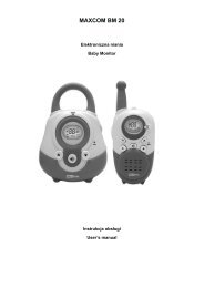
INSTAllATION<br />
n Mobile Installation<br />
2<br />
1 Clean and dry the installation location.<br />
Do not install the bracket close to an air bag.<br />
2 Remove the release paper from the base<br />
of the panel bracket, then secure it in<br />
place using the 3 supplied self-tapping<br />
screws.<br />
• Allow the panel to set for a while, to ensure<br />
it remains fast. Otherwise, vibrations may<br />
occur.<br />
• After removing the release paper, it cannot<br />
be reused.<br />
3 Attach the panel holder to the panel<br />
bracket using the 2 supplied SEMS<br />
screws.<br />
4 Attach the <strong>RC</strong>-D7 0 to the panel holder<br />
so that it locks in place.<br />
n Fixed Station<br />
1 Attach the panel holder to the base<br />
stand using the 2 supplied SEMS<br />
screws.<br />
2 Attach the <strong>RC</strong>-D7 0 to the panel<br />
holder so that it locks in place.<br />
Panel holder<br />
Adhesive tape<br />
Panel holder<br />
Tapping screw<br />
(4 mm x 2 mm)<br />
Flat washer<br />
Panel<br />
bracket<br />
SEMS screw<br />
(M4 x 0 mm)<br />
SEMS screw (M4<br />
x 0 mm)<br />
Base stand
cONNEcTION TO Pc<br />
Use a PG-5G (option) cable when connecting the <strong>RC</strong>-D7 0 to a computer D-SUB<br />
terminal.<br />
cOM terminal pin<br />
NC<br />
RXD<br />
GND<br />
CTS<br />
TM-V71<br />
NC<br />
NC<br />
RTS<br />
TXD<br />
cONNEcTION TO TM-V71<br />
Panel jack<br />
Modular plug cable<br />
Line filter<br />
PG-5G (option)<br />
Installing the Line Filter<br />
Install the line filter approximately 3 cm from the<br />
connector.<br />
PG-5G pin configuration (cross connection)<br />
Connect the <strong>RC</strong>-D7 0 to the TM-V7 using the supplied cable.<br />
Line filter Panel jack<br />
Approx. 3 cm<br />
To PC 9-pin<br />
D-SUB terminal<br />
<strong>RC</strong>-<strong>D710</strong><br />
3
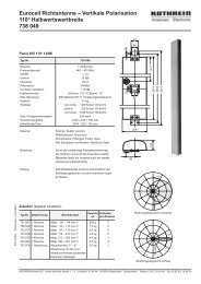
cONNEcTION TO PG-5J<br />
When using the <strong>RC</strong>-D7 0 with a transceiver other than the TM-V7 , attach the<br />
<strong>RC</strong>-D7 0 to the transceiver using the PG-5J (option).<br />
4<br />
DATA terminal<br />
Line filter<br />
Panel jack<br />
dATA terminal pin<br />
(PG-5J)<br />
SQC<br />
NC<br />
PR9 PKS<br />
GND<br />
Transceiver<br />
PKD<br />
To 3.8 V DC power supply<br />
or 2 V vehicle battery<br />
Black (—)<br />
cable<br />
6 pin mini-DIN cable<br />
Red (+)<br />
cable<br />
DC power cable<br />
DATA terminal<br />
<strong>RC</strong>-<strong>D710</strong> Modular plug cable<br />
No. Name I/O Function<br />
q PKD O<br />
w GND — GND<br />
e PKS O<br />
r PR9 I<br />
t NC — No connection<br />
y SQC I<br />
Panel jack<br />
TNC data output<br />
2 Vp-p/ 10 kΩ (9600 bps data)<br />
40 mVp-p/ 10 kΩ (1200 bps data)<br />
PG-5J<br />
Line filter<br />
Data standby control signal output<br />
Open corrector TX : L level / RX : Hi<br />
impedance<br />
TNC data input (9600 bps)<br />
350 mVp-p to 600 mVp-p/ 10 kΩ<br />
Squelch control signal input<br />
SQL Open: H level / Close: L level
n Power cable connection (PG-5J)<br />
Fixed Station<br />
In order to use the PG-5J for fixed station operation, you will need a separate<br />
3.8 V DC power supply that must be purchased separately.<br />
Note: Do not plug the DC power supply into an AC outlet until you make all connections.<br />
Mobile Installation<br />
Be sure to use a 2 V vehicle battery that has sufficient current capacity. If the<br />
current to the PG-5J is insufficient, the display may darken during transmission<br />
or the transmit output power may drop excessively. Never connect the<br />
transceiver to a 24 V battery.<br />
Note: Install the PG-5J Interface Box using the included screw set in a location where it will<br />
not interfere with driving.<br />
n Replacing Fuses (PG-5J)<br />
If the fuse blows, determine the cause, then correct the problem. After the<br />
problem is resolved, replace the fuse. If newly installed fuses continue to<br />
blow, disconnect the power cable and contact your authorized Kenwood<br />
dealer or an authorized Kenwood service center for assistance.<br />
Only use fuses of the specified type and rating; otherwise the PG-5J could be damaged.<br />
Fuse holder<br />
Fuse<br />
5
GETTING ACQUAINTED<br />
OPERATION PANEl (FRONT) <br />
n IN NORMAlMODE<br />
q CALL<br />
Press [CALL] to select the Call channel.<br />
Press [CALL] (1s) to start Call scan.<br />
w VFO<br />
Press [VFO] to enter VFO mode , then rotate the Tuning control to select an<br />
operating frequency.<br />
Press [VFO] (1s) to start VFO scan.<br />
e MR<br />
Press [MR] to enter Memory Channel mode, then rotate the Tuning control to<br />
select a Memory channel.<br />
Press [MR] (1s) to start Memory scan.<br />
r Tuning Control<br />
Rotate to select an operating frequency or Memory channel, change the scan<br />
direction, etc.<br />
Press the Tuning control to enter MHz mode (while in VFO or Call mode) or to<br />
toggle the display between the channel name and frequency (while in Memory<br />
Channel mode).<br />
Press Tuning control (1s) to start MHz scan or Group scan.<br />
t KEY<br />
Press [KEY] to turn the APRS key function ON and OFF.<br />
Note: For APRS key functions, refer to the APRS explanation.<br />
y F<br />
Press [F] to enter Function mode.<br />
Press [F] (1s) to turn the transceiver key lock function ON and OFF.
u TONE<br />
Press [TONE] to turn the Tone function ON.<br />
Each time you press [TONE] to toggle the functions as follows: Tone ON >><br />
CTCSS ON >> DCS ON >> OFF.<br />
i REV<br />
Press [REV] to turn the Reverse function ON or OFF.<br />
Press [REV] (1s) to turn the Automatic Simplex Checker ON.<br />
o LOW<br />
Press [LOW] to toggle the transmit output power as follows: High Power (with<br />
TM-V 1(A/E) K, E types only) –> Middle Power –> Low Power.<br />
!0 PF1<br />
Press [PF1] to activate its programmable function.<br />
!1 PF2<br />
Press [PF2] to activate its programmable function.<br />
!2 BAND SEL (VOL) Control<br />
Rotate the [BAND SEL] control to adjust the speaker volume.<br />
Press the left [BAND SEL] to select the A band. Press the right [BAND SEL]<br />
to select the B band.<br />
Press [BAND SEL] (1s) to toggle between single and dual-band mode.<br />
!3 SQL Control<br />
Rotate the [SQL] control to adjust the squelch level. Clockwise opens the<br />
squelch and counterclockwise tightens the squelch.<br />
!4 TNC<br />
Press [TNC] to turn built-in TNC ON and the APRS (or NAVITRA) mode ON.<br />
Each time you press [TNC], the mode toggles as follows: APRS (or<br />
NAVITRA) mode ON >> PACKET mode ON >> TNC OFF.<br />
• When the built-in TNC turns on, “OPENING TNC” appears on the display.<br />
• When “OPENING TNC” appears on the display, the mode cannot be changed.<br />
!5 PM<br />
Press [PM] to enters the PM (Programmable Memory) channel selection<br />
mode.<br />
!6<br />
Press [ ] to turn the transceiver power ON and OFF.
n IN FUNCTION MODE<br />
q C.IN<br />
Press [C.IN] to store the current operating frequency to the Call channel.<br />
w M>V<br />
Press [M>V] to copy the current Memory channel or Call channel to the VFO<br />
(memory shift).<br />
e M.IN<br />
Select a Memory channel, then press [M.IN] to store the current operating<br />
frequency in the Memory channel.<br />
r Tuning Control<br />
Press the Tuning control to enter Menu mode.<br />
t F OFF<br />
Press [F OFF] to return Normal mode.<br />
y T.SEL<br />
While Tone, CTCSS, or DCS is ON, press [T.SEL] to enter CTCSS or DCS<br />
setup mode.<br />
u SHIFT<br />
Press [SHIFT] to enter Offset Direction selection mode. Each time you press<br />
[SHIFT], the offset direction toggles as follows:<br />
plus (+) direction –> minus (–) direction –> – . MHz (with TM-V 1(E) E type<br />
only) –> OFF.<br />
i MUTE<br />
Press [MUTE] to turn the Mute function ON or OFF.<br />
o VISUAL<br />
Press [VISUAL] to turn the Visual Scan function ON and OFF.<br />
!0 BAND SEL (VOL) Control<br />
Rotate the [BAND SEL] control to adjust the speaker volume.<br />
Press [BAND SEL] to select a frequency band.
!1 SQL Control<br />
Rotate the [SQL] control to adjust the squelch level. Clockwise opens the<br />
squelch and counterclockwise tightens the squelch.<br />
!2 DX<br />
Press [DX] to turn the DX PacketClusters Monitor ON and OFF.<br />
!3 P.IN<br />
Press [P.IN] to enter PM Channel registration mode.<br />
!4<br />
Press [ ] to turn the transceiver power ON and OFF.<br />
OPERATION PANEl (REAR & lEFT)<br />
q GPS<br />
Connect the GPS receiver or the Weather Station to this jack with using<br />
supplied cable with a 2.5 mm (1/10") 3-conductor plug.<br />
w COM<br />
This terminal is for connecting to a PC. Use a PG-5G (option) cable when<br />
connecting the built-in TNC to a computer D-SUB terminal.<br />
e Panel jack<br />
Connect the TM-V 1 or PG-5J to this jack using the supplied Modular plug<br />
cable.
DIsPlAy <br />
10<br />
<br />
Indicator Description<br />
Clock display (Setting Time: Menu 525)<br />
Appears when there is a transmission band available.<br />
Blinks when the cross-band repeater is ON (with TM-V 1(A) K<br />
type only).<br />
Appears when there is an operation band available.<br />
Blinks when the wireless remote control is ON (with TM-<br />
V 1(A) K type only).<br />
Appears when the Tone function is ON.<br />
Appears when the CTCSS function is ON.<br />
Appears when the DCS function is ON.<br />
Appears when the Shift function is set to plus.<br />
Appears when the Shift function is set to minus.<br />
Appears when the Reverse function is ON.<br />
Appears when the ASC function is ON.<br />
Blinks when the ASC function is performing an OK check.<br />
Appears while in AM mode.<br />
Appears while in FM mode.<br />
Appears while in Narrow FM mode.<br />
Appears when the selected channel is registered while in<br />
Memory Input mode.
Indicator Description<br />
Displays the Memory channel and Menu number.<br />
Appears when the Memory Channel Lockout function is ON.<br />
Appears while using High output power.<br />
Blinks when the temperature protection circuit (transmit power<br />
save) turns on. (with TM-V 1(A/E) K, E types only)<br />
Appears while using Middle output power.<br />
Blinks when the temperature protection circuit (transmit power<br />
save) turns on.<br />
Appears while using Low output power.<br />
Displays the operating frequency.<br />
Appears when receiving a busy signal.<br />
Performs as an S meter when receiving a signal and displays<br />
the selected power level while transmitting.<br />
Appears while transmitting.<br />
Appears while using the External data band.<br />
Appears while using the Internal data band.<br />
Appears when the data terminal is set as 00 (bps).<br />
Appears when mute function is ON.<br />
Appears while making a continuous recording.<br />
Appears while in EchoLink Sysop mode.<br />
Appears when the Key Lock function is ON.<br />
Displays the PM channel number.<br />
Appears when Weather Alert is ON.<br />
Blinks when receiving a signal. (with TM-V 1(A) K type only)<br />
11
OPERATION PANEl (FRONT) <br />
n IN NORMAlMODE<br />
q Tuning Control<br />
12<br />
Press [F], then press the Tuning control to enter Menu mode.<br />
w F<br />
Press [F] to enter Function mode.<br />
e TNC<br />
Each time you press [TNC], the mode toggles between APRS (or NAVITRA)<br />
mode ON and PACKET mode ON.<br />
• When “OPENING TNC” appears on the display, the mode cannot be changed.<br />
r PM<br />
Press [PM] to enters the PM (Programmable Memory) channel selection<br />
mode.<br />
t<br />
Press [ ] to turn the <strong>RC</strong>-D 10 power ON and OFF.<br />
Note: For [MSG], [LIST], [BCON], [POS], and [P.MON] keys, refer to the APRS explanation.
n IN FUNCTION MODE<br />
q Tuning Control<br />
Press the Tuning control to enter Menu mode.<br />
w F OFF<br />
Press [F OFF] to return Normal mode.<br />
e DX<br />
Press [DX] to turn the DX PacketClusters Monitor ON and OFF.<br />
r P.IN<br />
Press [P.IN] to enter PM Channel registration mode.<br />
t<br />
Press [ ] to turn the <strong>RC</strong>-D 10 power ON and OFF.<br />
Note: For [WXi] key, refer to the APRS explanation.<br />
13
14<br />
BASIC OPERATIONS (<strong>RC</strong>-<strong>D710</strong> + TM-V71)<br />
SwITChINg ThE POwER ON/ OFF<br />
Press the [ ] switch to switch the transceiver ON.<br />
Press the [ ] switch again to switch the transceiver OFF.<br />
ADjuSTINg ThE VOluME<br />
Rotate the [BAND SEL] (VOL) control of your selected band clockwise to<br />
increase the volume and counterclockwise to decrease the volume.<br />
ADjuSTINg ThE SQuElCh<br />
Rotate the [SQL] control of your selected band, when no signals are present, and<br />
select the squelch level at which the background noise is just eliminated.
SElECTINg A BAND<br />
Press the left [BAND SEL] control to select band A and the right [BAND SEL]<br />
control to select band B.<br />
• The icon appears at the top of the band on which you are operating and the<br />
icon appears at the top of the band on which you are currently set to transmit.<br />
Band A (left [BAND SEL] control):<br />
Band B (right [BAND SEL] control):<br />
15
Pressing [PF2] allows you to switch the operating band between bands A and B,<br />
while maintaining the original band as the transmit band.<br />
Band A is the transmit band and band B is the operating band:<br />
16<br />
Band A is both the transmit and operating band:<br />
SElECTINg DuAl BAND MODE/ SINglE BAND MODE<br />
You can switch the transceiver between dual band operation and single band<br />
operation by pressing [BAND SEL] (1s) of your selected band.<br />
Dual band mode:
Single band mode (band A only):<br />
Note: You can also turn the center partition bar display off {Menu No. 527}.<br />
SElECTINg A FREQuENCy BAND<br />
You can change the default frequency bands for bands A and B.<br />
1 Select band A or B by pressing the [BAND SEL] control or [PF2].<br />
2 Press [F], [BAND SEL] of your selected band.<br />
• Each time you press [F], [BAND SEL], you cycle to the next frequency band.<br />
17
SElECTINg AN OPERATINg MODE<br />
There are 3 operating modes available to choose from: VFO mode, Memory<br />
Channel mode, and Call Channel mode.<br />
■ VFO Mode<br />
18<br />
VFO mode allows you to manually change the operating frequency.<br />
1 Press [VFO] to enter VFO mode.<br />
2 Rotate the Tuning control to select your desired operating frequency.<br />
■ Memory Channel Mode<br />
Memory Channel mode allows you to quickly select a frequently used<br />
frequency and related data which you have saved in the transceiver memory.<br />
1 Press [MR] to enter Memory Channel mode.<br />
2 Rotate the Tuning control to select your desired Memory channel.
■ Call Channel Mode<br />
Call Channel mode allows you to quickly select a preset channel to allow<br />
immediate calls on that frequency. The Call channel can be conveniently used<br />
as an emergency channel within your group.<br />
1 Select your desired band (A or B).<br />
2 Press [CALL] to enter Call Channel mode.<br />
• The icon appears on the display.<br />
3 Press [CALL] again to return to your previous operating frequency.<br />
TRANSMITTINg<br />
1 Select your desired band and frequency/channel.<br />
2 Press and hold the microphone [PTT] switch and speak into the microphone to<br />
transmit.<br />
• The icon and the RF power meter appear on the display for the selected<br />
transmit band. The RF power meter shows the relative transmit output power.<br />
• The / / icon(s) appear on the display, depending on what output power you<br />
have selected.<br />
3 When you finish speaking, release the [PTT] switch.<br />
19
20<br />
MENU MODE<br />
Many functions on this <strong>RC</strong>-<strong>D710</strong> are selected or configured through the Menu<br />
instead of physical controls. Once you become familiar with the Menu system,<br />
you will appreciate the versatility it offers.<br />
MENU AccEss<br />
1 Press [F], Tuning control to access the Menu.<br />
• The setup category name appears on the display.<br />
<br />
<br />
2 Rotate the Tuning control to select your desired setup category.<br />
3 Press the Tuning control to set up the current category.<br />
• The Menu name and number appears on the display.<br />
4 Rotate the Tuning control to select your desired Menu.<br />
5 Press the Tuning control to set up the current Menu.<br />
6 Rotate the Tuning control to select your desired value for the selected Menu.<br />
7 Press the Tuning control to set the selected value.<br />
8 Repeat steps 2 to 7 to set up additional Menus.<br />
• Press [ESC] at any time to exit Menu mode.<br />
• Press [BACK] at any time to cancel the Menu setup and return to the Menu<br />
selection.
MENU cONfigUrAtiON<br />
Menu<br />
No.<br />
AUDIO <br />
Display Description<br />
Setting<br />
Values<br />
Default<br />
Setting<br />
000 KEY BEEP Beep sound OFF/ ON ON<br />
001 BEEP VOLUME Beep volume level<br />
002 EXT.SPEAKER<br />
External speaker output<br />
mode<br />
003 1 ANNOUNCE Voice announcement mode<br />
004 1<br />
005 1<br />
ANNOUNCE<br />
LANGUAGE<br />
ANNOUNCE<br />
VOLUME<br />
006 1 ANNOUNCE SPEED<br />
Voice announcement<br />
language<br />
Voice announcement<br />
volume<br />
Voice announcement<br />
speed<br />
LEVEL 1 ~<br />
LEVEL 7<br />
MODE 1/<br />
MODE 2<br />
OFF/ AUTO/<br />
MANUAL<br />
ENGLISH/<br />
JAPANESE<br />
LEVEL 1 ~<br />
LEVEL 7<br />
SPEED 0 ~<br />
SPEED 4<br />
LEVEL 5<br />
MODE 1<br />
AUTO<br />
ENGLISH<br />
LEVEL 5<br />
SPEED 1<br />
007 1 PLAYBACK REPEAT Recording playback repeat OFF/ ON OFF<br />
008 1<br />
009 1<br />
Menu<br />
No.<br />
PLAYBACK<br />
INTERVAL<br />
CONTINUOUS<br />
RECORDING<br />
Playback repeat interval<br />
time<br />
0 ~ 60 s 10 s<br />
Continuous recording OFF/ ON OFF<br />
AUDIO <br />
Display Description<br />
Setting<br />
Values<br />
Default<br />
Setting<br />
000 KEY BEEP Beep sound OFF/ ON ON<br />
001 BEEP VOLUME Beep volume level<br />
LEVEL 1 ~<br />
LEVEL 3<br />
LEVEL 2<br />
21
Menu<br />
No.<br />
22<br />
100<br />
TX/RX <br />
Display Description<br />
PROGRAMMABLE<br />
VFO<br />
Programmable VFO setup<br />
101 STEP Step frequency<br />
102 MODULATION<br />
Modulation/demodulation<br />
mode<br />
Setting<br />
Values<br />
Varies with<br />
the selected<br />
frequency band<br />
Varies with<br />
the selected<br />
frequency band<br />
Varies with<br />
the selected<br />
frequency band<br />
Default<br />
Setting<br />
103 VHF AIP VHF band AIP OFF/ ON OFF<br />
104 UHF AIP UHF band AIP OFF/ ON OFF<br />
105 S-METER SQUELCH S-meter squelch OFF/ ON OFF<br />
106<br />
107<br />
S-METER SQL<br />
HANGUP TIME<br />
MUTE HANGUP<br />
TIME<br />
S-meter squelch hang up<br />
time<br />
Mute hang up time setup<br />
OFF/ 125/ 250/<br />
500 ms<br />
OFF/ 125/ 250/<br />
500/ 750/ 1000<br />
ms<br />
–<br />
–<br />
–<br />
OFF<br />
OFF<br />
108 BEAT SHIFT Beat shift OFF/ ON OFF<br />
109 TOT Time-out timer 3/ 5/ 10 min 10 min<br />
110 2 WEATHER ALERT Weather alert OFF/ ON OFF<br />
Menu<br />
No.<br />
MEMORY <br />
Display Description<br />
200 MEMORY NAME Memory name setup<br />
201 RECALL METHOD<br />
Memory channel recall<br />
method<br />
Setting<br />
Values<br />
Up to 8<br />
characters<br />
ALL BANDS/<br />
CURRENT<br />
Default<br />
Setting<br />
–<br />
ALL BANDS<br />
202 LOCKOUT Memory channel lockout OFF/ ON OFF<br />
203 GROUP LINK<br />
Memory group link<br />
registration<br />
204 EchoLink MEMORY EchoLink memory setting<br />
205 EchoLink SPEED<br />
EchoLink memory<br />
transmission speed<br />
Up to 10 digits<br />
(0 ~ 9)<br />
Up to 8<br />
characters<br />
for EchoLink<br />
memory name<br />
Up to 8 digits<br />
for DTMF code<br />
FAST/ SLOW FAST<br />
–<br />
–
Menu<br />
No.<br />
DTMF <br />
Display Description<br />
Setting<br />
Values<br />
Default<br />
Setting<br />
300 DTMF HOLD DTMF transmission hold OFF/ ON OFF<br />
301 DTMF MEMORY DTMF memory<br />
302 DTMF SPEED<br />
DTMF memory<br />
transmission speed<br />
303 DTMF PAUSE DTMF pause code time<br />
Up to 8<br />
characters for<br />
DTMF memory<br />
name<br />
Up to 16 digits<br />
for DTMF code<br />
FAST/ SLOW FAST<br />
100/ 250/ 500/<br />
750/ 1000/<br />
1500/ 2000 ms<br />
–<br />
500 ms<br />
304 DTMF KEY LOCK DTMF key lock OFF/ ON OFF<br />
Menu<br />
No.<br />
REPEATER <br />
Display Description<br />
400 OFFSET FREQUENCY Offset frequency<br />
401 3<br />
AUTO REPEATER<br />
OFFSET<br />
402 1750 TX HOLD<br />
Setting<br />
Values<br />
See<br />
explanation<br />
Default<br />
Setting<br />
Auto Repeater Offset OFF/ ON ON<br />
Transmission hold when<br />
transmitting a 1750 Hz tone<br />
403 2 REPEATER MODE Repeater mode<br />
OFF/ ON OFF<br />
CROSS BAND/<br />
LOCKED TX:<br />
A-BAND/<br />
LOCKED TX:<br />
B-BAND<br />
–<br />
CROSS BAND<br />
404 2 REPEATER TX HOLD Repeater transmission hold ON/ OFF OFF<br />
405 2 REPEATER ID Repeater ID registration<br />
406 2 REPEATER ID TX Repeater ID transmission<br />
Up to 12<br />
characters<br />
OFF/ MORSE/<br />
VOICE<br />
–<br />
OFF<br />
23
Menu<br />
No.<br />
24<br />
500<br />
AUX <br />
Display Description<br />
POWER ON<br />
MESSAGE<br />
Power on message setup<br />
501 BRIGHTNESS Display brightness<br />
Setting<br />
Values<br />
Up to 8<br />
characters<br />
OFF/ LEVEL 1<br />
~ LEVEL 8<br />
Default<br />
Setting<br />
HELLO !!<br />
LEVEL 8<br />
502 AUTO BRIGHTNESS Display auto brightness OFF/ ON OFF<br />
503 BACKLIGHT COLOR Backlight color<br />
504 CONTRAST Display contrast<br />
505<br />
DISPLAY REVERSE<br />
MODE<br />
507 PANEL PF1<br />
508 PANEL PF2<br />
509 MIC PF1(PF)<br />
510 MIC PF2(MR)<br />
511 MIC PF3(VFO)<br />
512 MIC PF4(CALL)<br />
Display reverse mode<br />
PF1 key programmable<br />
function value<br />
PF2 key programmable<br />
function value<br />
Microphone PF1 key<br />
programmable function<br />
value<br />
Microphone PF2 key<br />
programmable function<br />
value<br />
Microphone PF3 key<br />
programmable function<br />
value<br />
Microphone PF4 key<br />
programmable function<br />
value<br />
AMBER/<br />
GREEN<br />
LEVEL 1 ~<br />
LEVEL 16<br />
POSITIVE/<br />
NEGATIVE<br />
See<br />
explanation<br />
See<br />
explanation<br />
See<br />
explanation<br />
See<br />
explanation<br />
See<br />
explanation<br />
See<br />
explanation<br />
AMBER<br />
LEVEL 8<br />
POSITIVE<br />
WX CH<br />
(K type)<br />
FRQ.BAND<br />
(E/ M4 types)<br />
CTRL<br />
A/B<br />
MR<br />
VFO<br />
CALL<br />
(K/ M4 types)<br />
1750<br />
(E type)<br />
513 MIC KEY LOCK Microphone key lock OFF/ ON OFF<br />
514 SCAN RESUME Scan resume method<br />
515 VISUAL SCAN<br />
Number of Channels for<br />
Visual Scan<br />
516 APO Auto Power Off time<br />
TIME/<br />
CARRIER/<br />
SEEK<br />
MODE 1: 31ch/<br />
MODE 2 : 61ch/<br />
MODE 3 : 91ch/<br />
MODE 4 : 181ch<br />
OFF/ 30/ 60/<br />
90/ 120/ 180<br />
(minutes)<br />
TIME<br />
MODE 2 : 61ch<br />
OFF
Menu<br />
No.<br />
517 EXT. DATA BAND<br />
AUX <br />
Display Description<br />
518 EXT. DATA SPEED<br />
519<br />
PC PORT<br />
BAUDRATE<br />
External TNC data band<br />
type<br />
External TNC data<br />
communications speed<br />
PC terminal baud rate<br />
speed<br />
520 SQC SOU<strong>RC</strong>E SQC output type<br />
Setting<br />
Values<br />
A-BAND/<br />
B-BAND/<br />
TX:A-BAND<br />
RX:B-BAND/<br />
RX:A-BAND<br />
TX:B-BAND<br />
Default<br />
Setting<br />
A-BAND<br />
1200/ 9600 bps 1200 bps<br />
9600/ 19200/<br />
38400/ 57600<br />
bps<br />
OFF/ BUSY/<br />
SQL/ TX/<br />
BUSY or TX/<br />
SQL or TX<br />
9600 bps<br />
BUSY or TX<br />
521 AUTO PM STORE Automatic PM entry OFF/ ON ON<br />
522 2 REMOTE ID<br />
523 2<br />
REMOTE ANSWER<br />
BACK<br />
524 DATE Date<br />
525 TIME Clock time<br />
526 TIME ZONE Time zone<br />
527<br />
528<br />
529<br />
DISPLAY<br />
PARTITION BAR<br />
COM PORT<br />
BAUDRATE<br />
INT. DATA BAND<br />
(PACKET)<br />
Personal Identification<br />
Number<br />
000 ~ 999 000<br />
Answer back OFF/ ON ON<br />
See<br />
explanation<br />
See<br />
explanation<br />
UTC + 14:00 ~<br />
UTC − 14:00<br />
–<br />
–<br />
UTC<br />
Display partition bar OFF/ ON ON<br />
COM terminal baud rate<br />
speed<br />
Internal TNC data band<br />
(PACKET)<br />
9600/ 19200/<br />
38400/ 57600<br />
bps<br />
A-BAND/<br />
B-BAND/<br />
TX:A-BAND<br />
RX:B-BAND/<br />
RX:A-BAND<br />
TX:B-BAND<br />
9600 bps<br />
A-BAND<br />
25
Menu<br />
No.<br />
26<br />
500<br />
AUX <br />
Display Description<br />
POWER ON<br />
MESSAGE<br />
Power on message setup<br />
501 BRIGHTNESS Display brightness<br />
Setting<br />
Values<br />
Up to 8<br />
characters<br />
OFF/ LEVEL 1<br />
~ LEVEL 8<br />
Default<br />
Setting<br />
HELLO !!<br />
LEVEL 8<br />
502 AUTO BRIGHTNESS Display auto brightness OFF/ ON OFF<br />
503 BACKLIGHT COLOR Backlight color<br />
504 CONTRAST Display contrast<br />
505<br />
DISPLAY REVERSE<br />
MODE<br />
Display reverse mode<br />
AMBER/<br />
GREEN<br />
LEVEL 1 ~<br />
LEVEL 16<br />
POSITIVE/<br />
NEGATIVE<br />
AMBER<br />
LEVEL 8<br />
POSITIVE<br />
521 AUTO PM STORE Automatic PM entry OFF/ ON ON<br />
524 DATE Date<br />
525 TIME Clock time<br />
526 TIME ZONE Time zone<br />
528<br />
COM PORT<br />
BAUDRATE<br />
COM terminal baud rate<br />
speed<br />
See<br />
explanation<br />
See<br />
explanation<br />
UTC + 14:00 ~<br />
UTC − 14:00<br />
9600/ 19200/<br />
38400/ 57600<br />
bps<br />
–<br />
–<br />
UTC<br />
9600 bps
Menu<br />
No.<br />
600<br />
601<br />
602<br />
603<br />
APRS<br />
Display Description<br />
MY CALLSIGN Call sign entry<br />
BEACON TYPE Beacon type<br />
DATA BAND<br />
*<strong>RC</strong>-<strong>D710</strong> +<br />
TM-V71<br />
DATA SPEED<br />
Data band type<br />
BASIC SETTING<br />
INTERNAL TNC<br />
Data communications<br />
speed<br />
DCD SENSE DCD sense type<br />
TX DELAY TX delay time<br />
BAUD RATE Baud rate speed<br />
INPUT GPS data input type<br />
GPS PORT<br />
OUTPUT GPS data output type<br />
FORMAT Way point format<br />
NAME Way point name<br />
WAYPOINT<br />
OUTPUT Way point output type<br />
Setting<br />
Values<br />
Up to 9<br />
characters<br />
APRS/<br />
NAVITRA<br />
A-BAND/<br />
B-BAND/<br />
TX:A-BAND<br />
RX:B-BAND/<br />
RX:A-BAND<br />
TX:B-BAND<br />
Default<br />
Setting<br />
NOCALL<br />
APRS<br />
A-BAND<br />
1200/ 9600 bps 1200 bps<br />
D or RxD<br />
BAND/<br />
BOTH BAND/<br />
IGNORE DCD<br />
*<strong>RC</strong>-<strong>D710</strong> +<br />
TM-V71<br />
ON/<br />
IGNORE DCD<br />
*<strong>RC</strong>-<strong>D710</strong> +<br />
PG-5J<br />
100/ 150/ 200/<br />
300/ 400/ 500/<br />
750/ 1000 ms<br />
2400/ 4800/<br />
9600 bps<br />
OFF/ GPS/<br />
WEATHER(Da<br />
vis)/ WEATHER<br />
(PeetBros)<br />
OFF/<br />
WAYPOINT/<br />
DGPS<br />
NMEA/<br />
MAGELLAN/<br />
KENWOOD<br />
6-CHAR ~ 9-<br />
CHAR<br />
ALL/ LOCAL/<br />
FILTERED<br />
D or RxD<br />
BAND<br />
ON<br />
200 ms<br />
4800 bps<br />
OFF<br />
OFF<br />
NMEA<br />
6-CHAR<br />
ALL<br />
27
Menu<br />
No.<br />
28<br />
604<br />
605<br />
606<br />
607<br />
608<br />
609<br />
610<br />
611<br />
APRS<br />
Display Description<br />
COM PORT<br />
Setting<br />
Values<br />
Default<br />
Setting<br />
OUTPUT COM port output OFF/ ON OFF<br />
NAME Name entry<br />
LATITUDE Latitude entry<br />
LONGITUDE Longitude entry<br />
MY POSITION<br />
BEACON INFORMATION<br />
See<br />
explanation<br />
See<br />
explanation<br />
See<br />
explanation<br />
SPEED Speed information setup OFF/ ON ON<br />
ALTITUDE Altitude information setup OFF/ ON ON<br />
POSITION<br />
AMBIGUITY<br />
POSITION<br />
COMMENT<br />
Position ambiguity mode<br />
Position comment<br />
TEXT Status text<br />
POSITION COMMENT<br />
STATUS TEXT<br />
OFF/ 1-DIGIT ~<br />
4-DIGIT<br />
See<br />
explanation<br />
See<br />
explanation<br />
−<br />
−<br />
−<br />
OFF<br />
Off Duty<br />
TX RATE Status text TX rate OFF/ 1/1 ~ 1/8 1/1<br />
POSITION LIMIT Position limit<br />
TYPE Packet filter type<br />
STATION ICON Station icon<br />
METHOD Method<br />
INITIAL INTERVAL Initial interval time<br />
PACKET FILTER<br />
STATION ICON<br />
BEACON TX ALGORITHM<br />
See<br />
explanation<br />
WHEATHER/<br />
DIGI/ MOBILE/<br />
OBJECT/<br />
NAVITRA/<br />
OTHERS<br />
See<br />
explanation<br />
MANUAL/ PTT/<br />
AUTO<br />
0.2/ 0.5/ 1/ 3/ 5/<br />
10/ 20/ 30 min<br />
−<br />
OFF<br />
Checked all<br />
W<br />
(KENWOOD icon)<br />
MANUAL<br />
3 min<br />
DECAY ALGORITHM Decay algorithm OFF/ ON ON<br />
PROPORTIONAL<br />
PATHING<br />
Proportional pathing OFF/ ON ON
Menu<br />
No.<br />
612<br />
613<br />
614<br />
615<br />
616<br />
617<br />
618<br />
619<br />
620<br />
621<br />
622<br />
APRS<br />
Display Description<br />
PACKET PATH<br />
Setting<br />
Values<br />
TYPE Packet path type See explanation<br />
NETWORK Network<br />
NETWORK<br />
Up to 9<br />
characters<br />
VOICE ALERT *<strong>RC</strong>-<strong>D710</strong> + TM-V71<br />
Default<br />
Setting<br />
APK102<br />
VOICE ALERT Voice alert OFF/ ON OFF<br />
CTCSS FREQUENCY CTCSS frequency<br />
WEATHER STATION<br />
See<br />
explanation<br />
100.0 Hz<br />
TX Weather TX OFF/ ON OFF<br />
TX INTERVAL Weather TX interval time 5/ 10/ 30 min 5 min<br />
DIGIPEAT (MY CALL)<br />
DIGIPEAT Digipeat OFF/ ON OFF<br />
UI CHECK<br />
TIME UI check time 0 ~ 250 sec 28 sec<br />
UIDIGI<br />
ALIASES<br />
UIFLOOD<br />
ALIASES<br />
SUBSTITUTION<br />
UITRACE<br />
ALIASES<br />
UIDIGI<br />
UIDIGI See explanation<br />
UIFLOOD<br />
UIFLOOD See explanation<br />
UITRACE<br />
UITRACE See explanation<br />
USER PHRASES<br />
USER PHRASES User phrases See explanation<br />
AUTO MESSAGE REPLY<br />
REPLY Reply message OFF/ ON OFF<br />
TEXT Auto message reply text<br />
REPLY TO Reply to<br />
Up to 50<br />
characters<br />
Up to 9<br />
characters<br />
−<br />
29
Menu<br />
No.<br />
30<br />
623<br />
624<br />
625<br />
626<br />
627<br />
628<br />
APRS<br />
Display Description<br />
MESSAGE Message group<br />
BLN BLN group<br />
RX BEEP RX Beep<br />
SPECIAL CALL Special call<br />
APRS VOICE<br />
*<strong>RC</strong>-<strong>D710</strong> +<br />
TM-V71<br />
DISPLAY AREA Display area<br />
GROUP FILTERING<br />
SOUND<br />
Setting<br />
Values<br />
Up to 59<br />
characters<br />
Up to 29<br />
characters<br />
OFF/ MESSAG<br />
E ONLY/ MINE/<br />
ALL NEW/ ALL<br />
Up to 9<br />
characters<br />
Default<br />
Setting<br />
ALL, QST, CQ,<br />
KWD<br />
−<br />
ALL<br />
APRS voice OFF/ ON ON<br />
INTERRUPT DISPLAY<br />
OFF/ HALF/<br />
ENTIRE<br />
*<strong>RC</strong>-<strong>D710</strong> +<br />
TM-V71<br />
OFF/ ENTIRE<br />
*<strong>RC</strong>-<strong>D710</strong><br />
+PG-5J<br />
−<br />
ENTIRE<br />
ENTIRE<br />
AUTO BRIGHTNESS Auto brightness OFF/ ON ON<br />
CHANGE COLOR Change color OFF/ ON ON<br />
SPEED, DISTANCE Speed/ distance<br />
DISPLAY UNIT 1<br />
mi/h mile/ Km/h<br />
mile/ Knots nm<br />
mi/h mile<br />
ALTITUDE, RAIN Altitude/ rain feet/inch/ m/nm feet/inch<br />
TEMPERATURE Temperature °F/ °C °F<br />
POSITION Position format<br />
GRID FORMAT Grid format<br />
DISPLAY UNIT 2<br />
NAVITRA GROUP<br />
dd°mm. mm’/<br />
dd°mm’ ss. s”<br />
MAIDENHEAD<br />
GRID/ SAR<br />
GRID (CONV)/<br />
SAR GRID<br />
(CELL)<br />
dd°mm. mm’<br />
MAIDENHEAD<br />
GRID<br />
GROUP MODE Group mode OFF/ ON OFF<br />
GROUP CODE Group code 3 characters 000
chArActEr ENtry<br />
Certain menus require you to enter characters, such as the power on message<br />
and memory names. When character entry is required, a cursor will appear on<br />
the display.<br />
1 Press the Tuning control.<br />
• The cursor will blink.<br />
2 Rotate the Tuning control to select your desired character.<br />
3 Press the Tuning control to set the selected character.<br />
• The cursor will move to the next digit.<br />
32<br />
• You can move the cursor to the left or right by pressing [←] or [→].<br />
• You can insert one space by pressing [SPACE].<br />
• You can insert a character by pressing [INS].<br />
• You can delete the selected character by pressing [CLR].<br />
4 Repeat steps 2 and 3 to enter the remaining characters.<br />
• Press [ESC] at any time to exit Menu mode.<br />
• Press [BACK] at any time to cancel the Menu setup and return to the Menu<br />
selection.
n Microphone Keypad character Entry (with tM-V71)<br />
The microphone keys can also be used to enter characters. Refer to the table<br />
below for characters corresponding to microphone keys.<br />
Key<br />
Character Display (with<br />
each press of the key)<br />
Key<br />
Character Display (with<br />
each press of the key)<br />
1 Q Z 1 7 P R S 7<br />
2 A B C 2 8 T U V 8<br />
3 D E F 3 9 W X Y 9<br />
4 G H I 4 0 (space) 0<br />
5 J K L 5 Not used<br />
6 M N O 6 # – / @<br />
For a memory name, status text, and message:<br />
Key Character Display (with each press of the key)<br />
1 q z 1 Q Z<br />
2 a b c 2 A B C<br />
3 d e f 3 D E F<br />
4 g h i 4 G H I<br />
5 j k l 5 J K L<br />
6 m n o 6 M N O<br />
7 p r s 7 P R S<br />
8 t u v 8 T U V<br />
9 w x y 9 W X Y<br />
0 (space) 0<br />
#<br />
Not used<br />
? ! ’ . , – /<br />
& # % ( ) < ><br />
; : ” @<br />
The microphone [A] ~ [D] keys have special functions assigned to them:<br />
[A]: Functions the same as [CLR]<br />
[B]: Functions the same as [←]<br />
[C]: Functions the same as [→]<br />
[D]: Functions the same as the Tuning control<br />
33
GENERAL INFORMATION<br />
34<br />
MAINTENANCE<br />
This product has been factory aligned and tested to specification before shipment.<br />
Attempting service or alignment without factory authorization can void the product<br />
warranty.<br />
SERVICE<br />
When returning this product to your dealer or service center for repair, pack it in<br />
its original box and packing material. Include a full description of the problem(s)<br />
experienced. Include your telephone number along with your name and address<br />
in case the service technician needs to contact you; if available, also include your<br />
fax number and e-mail address. Don’t return accessory items unless you feel<br />
they are directly related to the service problem.<br />
You may return this product for service to the authorized Kenwood dealer from<br />
whom you purchased it, or any authorized Kenwood service center. Please do<br />
not send subassemblies or printed circuit boards; send the complete product. A<br />
copy of the service report will be returned with the product.<br />
SERVICE NOTE<br />
If you desire to correspond on a technical or operational problem, please make<br />
your note legible, short, complete, and to the point. Help us help you by providing<br />
the following:<br />
• Model and serial number of equipment<br />
• Question or problem you are having<br />
• Other equipment in your station pertaining to the problem<br />
Do not pack the equipment in crushed newspapers for shipment! Extensive damage may result<br />
during rough handling or shipping.<br />
Note:<br />
u Record the date of purchase, serial number and dealer from whom this product was purchased.<br />
u For your own information, retain a written record of any maintenance performed on this<br />
product.<br />
u When claiming warranty service, please include a photocopy of the bill of sale or other<br />
proof-of-purchase showing the date of sale.<br />
CLEANING<br />
To clean the case of this product, use a neutral detergent (no strong chemicals)<br />
and a damp cloth.
SPECIFICATIONS<br />
Specifications are subject to change without notice due to advancements in<br />
technology.<br />
Supply voltage 10 V DC (9 ~ 11 V DC) <br />
Current Less than 450 mA<br />
Operating temperature range –20°C ~ +60°C (–4°F ~ +140°F)<br />
Dimensions<br />
(W x H x D)<br />
Without projections 155 x 70 x 38 mm (6.10" x 2.76" x 1.50")<br />
With projections 156 x 71 x 56 mm (6.14" x 2.80" x 2.21")<br />
Weight (approx.) 300 g (10.6 oz.)<br />
To download the MCP-2A software, go to:<br />
http://www.kenwood.com/i/products/info/amateur/software_download.html<br />
Note: This URL may change without notice.<br />
35