A Software Defined Radio for the Masses, Part 3
A Software Defined Radio for the Masses, Part 3
A Software Defined Radio for the Masses, Part 3

Create successful ePaper yourself
Turn your PDF publications into a flip-book with our unique Google optimized e-Paper software.
occurs on a 1-ms linear slope.<br />
To determine <strong>the</strong> AGC gain requirement,<br />
we must detect <strong>the</strong> envelope of<br />
<strong>the</strong> demodulated signal. This is easily<br />
accomplished by converting from Cartesian<br />
to polar coordinates. The value<br />
of M() is <strong>the</strong> envelope, or magnitude,<br />
of <strong>the</strong> signal. The phase vector can be<br />
ignored insofar as AGC is concerned.<br />
We will need to save <strong>the</strong> phase values,<br />
though, <strong>for</strong> conversion back to<br />
Cartesian coordinates later. Once we<br />
have <strong>the</strong> magnitudes stored in M(), it<br />
is a simple matter to find <strong>the</strong> peak<br />
magnitude and store it in Vpk with <strong>the</strong><br />
function nspdMax. After checking to<br />
prevent a divide-by-zero error, we compute<br />
a gain factor relative to 50% of<br />
<strong>the</strong> full-scale value. This provides 6 dB<br />
of headroom from <strong>the</strong> signal peak to<br />
<strong>the</strong> full-scale output value of <strong>the</strong> DAC.<br />
On each pass, <strong>the</strong> gain factor is stored<br />
in <strong>the</strong> G() array so that we can find<br />
<strong>the</strong> peak gain reduction during <strong>the</strong><br />
hang-time period using <strong>the</strong> nspdMin<br />
function. The peak gain-reduction factor<br />
is <strong>the</strong>n stored in <strong>the</strong> Gain variable.<br />
Note that Gain is saved as a ratio and<br />
not in decibels, so that no log/antilog<br />
conversion is needed.<br />
The next step is to limit Gain to <strong>the</strong><br />
MaxGain value, which may be set by<br />
<strong>the</strong> user. This system functions much<br />
like an IF-gain control allowing Gain<br />
to vary from negative values up to <strong>the</strong><br />
MaxGain setting. Although not provided<br />
in <strong>the</strong> example code, it is a<br />
simple task to create a front panel control<br />
in Visual Basic to manually set<br />
<strong>the</strong> MaxGain value.<br />
Next, we determine if <strong>the</strong> gain must<br />
be increased, decreased or left unchanged.<br />
If Gain is less than PrevGain<br />
(that is <strong>the</strong> Gain setting from <strong>the</strong> signal<br />
block stored on <strong>the</strong> last pass<br />
through <strong>the</strong> code), we ramp <strong>the</strong> gain<br />
down linearly over 44 samples. This<br />
yields an attack time of approximately<br />
1 ms at a 44,100-Hz sampling rate.<br />
GainStep is <strong>the</strong> slope of <strong>the</strong> ramp per<br />
sample time calculated from <strong>the</strong><br />
PrevGain and Gain values. We <strong>the</strong>n<br />
incrementally ramp down <strong>the</strong> first 44<br />
samples by <strong>the</strong> GainStep value. Once<br />
ramped to <strong>the</strong> new Gain value, we<br />
multiply <strong>the</strong> remaining samples by <strong>the</strong><br />
fixed Gain value.<br />
If Gain is increasing from <strong>the</strong><br />
PrevGain value, <strong>the</strong> process is simply<br />
reversed. If Gain has not changed, all<br />
samples are multiplied by <strong>the</strong> current<br />
Gain setting. After <strong>the</strong> signal block has<br />
been processed, Gain is saved in<br />
PrevGain <strong>for</strong> <strong>the</strong> next signal block.<br />
Finally, nspdbThresh1 implements a<br />
hard limiter at roughly <strong>the</strong> maximum<br />
output level of <strong>the</strong> DAC, to prevent<br />
overflow of <strong>the</strong> integer-variable output<br />
buffers.<br />
Send <strong>the</strong> Demodulated or<br />
Modulated Signal to <strong>the</strong><br />
Output Buffer<br />
The final step is to <strong>for</strong>mat <strong>the</strong> processed<br />
signal <strong>for</strong> output to <strong>the</strong> DAC.<br />
When receiving, <strong>the</strong> RealOut() signal<br />
is copied, sample by sample, into both<br />
<strong>the</strong> left and right channels. For<br />
transmiting, RealOut() is copied to <strong>the</strong><br />
right channel and ImagOut() is copied<br />
to <strong>the</strong> left channel of <strong>the</strong> DAC. If<br />
binaural receiving is desired, <strong>the</strong> I and<br />
Q signal can optionally be sent to <strong>the</strong><br />
right and left channels respectively,<br />
just as in <strong>the</strong> transmit mode.<br />
Private Sub cmdAGC_Click(Index As Integer)<br />
MaxGain = 1000 ‘Maximum digital gain = 60dB<br />
Select Case Index<br />
Case 0<br />
AGC = True<br />
AGCHang = 3 ‘3 x 0.04644 sec = 139 ms<br />
Case 1<br />
AGC = True<br />
AGCHang = 7 ‘7 x 0.04644 sec = 325 ms<br />
Case 2<br />
AGC = False ‘AGC Off<br />
End Select<br />
End Sub<br />
Private Sub cmdFilter_Click(Index As Integer)<br />
Select Case Index<br />
Case 0<br />
CalcFilter 300, 3000 ‘2.7KHz Filter<br />
Case 1<br />
CalcFilter 500, 1000 ‘500Hz Filter<br />
Case 2<br />
CalcFilter 700, 800 ‘100Hz Filter<br />
End Select<br />
End Sub<br />
Private Sub cmdMode_Click(Index As Integer)<br />
Select Case Index<br />
Case 0 ‘Change mode to USB<br />
SSB = True<br />
USB = True<br />
Case 1 ‘Change mode to LSB<br />
SSB = True<br />
USB = False<br />
End Select<br />
End Sub<br />
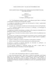
Figure 18 – Control Code <strong>for</strong> <strong>the</strong> Demo Front Panel<br />
Controlling <strong>the</strong><br />
Demonstration Code<br />
The SDR demonstration code (see<br />
Note 3) has a few selected buttons <strong>for</strong><br />
setting AGC hang time, filter selection<br />
and sideband selection. The code <strong>for</strong><br />
<strong>the</strong>se functions is shown in Fig 18. The<br />
code is self-explanatory and easy to<br />
modify <strong>for</strong> additional filters, different<br />
hang times and o<strong>the</strong>r modes of operation.<br />
Feel free to experiment.<br />
The Fully Functional SDR-1000<br />
<strong>Software</strong><br />
The SDR-1000, my nomenclature<br />
Nov/Dec 2002 9