A Software Defined Radio for the Masses, Part 3
A Software Defined Radio for the Masses, Part 3
A Software Defined Radio for the Masses, Part 3

Create successful ePaper yourself
Turn your PDF publications into a flip-book with our unique Google optimized e-Paper software.
only have to calculate <strong>the</strong> filter response<br />
once when <strong>the</strong> filter is first selected<br />
by <strong>the</strong> user.<br />
Fig 12 provides <strong>the</strong> code <strong>for</strong> an FFT<br />
fast-convolution filter. Using <strong>the</strong><br />
nspdbMpy2 routine, <strong>the</strong> signal-spectrum<br />
magnitude bins, M(), are multiplied<br />
by <strong>the</strong> filter frequency-response<br />
magnitude bins, filterM(), to generate<br />
<strong>the</strong> resulting in-place filtered magnitude-response<br />
bins, M(). We <strong>the</strong>n use<br />
nspdbAdd2 to add <strong>the</strong> signal phase<br />
bins, P(), to <strong>the</strong> filter phase bins,<br />
filterP(), with <strong>the</strong> result stored inplace<br />
in <strong>the</strong> filtered phase-response<br />
bins, P(). Notice that FFT convolution<br />
can also be per<strong>for</strong>med in Cartesian<br />
coordinates using <strong>the</strong> method shown<br />
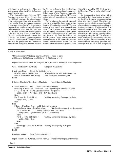
If AGC = True Then<br />
‘If true increment AGCLoop counter, o<strong>the</strong>rwise reset to zero<br />
AGCLoop = IIf(AGCLoop < AGCHang - 1, AGCLoop + 1, 0)<br />
nspdbrCartToPolar RealOut, ImagOut, M, P, BLKSIZE ‘Envelope Polar Magnitude<br />
Vpk = nspdMax(M, BLKSIZE) ‘Get peak magnitude<br />
If Vpk 0 Then ‘Check <strong>for</strong> divide by zero<br />
G(AGCLoop) = 16384 / Vpk ‘AGC gain factor with 6 dB headroom<br />
Gain = nspdMin(G, AGCHang) ‘Find peak gain reduction (Min)<br />
End If<br />
If Gain > MaxGain Then Gain = MaxGain ‘Limit Gain to MaxGain<br />
If Gain < PrevGain Then ‘AGC Gain is decreasing<br />
GainStep = (PrevGain - Gain) / 44 ’44 Sample ramp = 1 ms attack time<br />
For S = 0 To 43 ‘Ramp Gain down over 1 ms period<br />
M(S) = M(S) * (PrevGain - ((S + 1) * GainStep))<br />
Next<br />
For S = 44 To BLKSIZE - 1 ‘Multiply remaining Envelope by Gain<br />
M(S) = M(S) * Gain<br />
Next<br />
Else<br />
If Gain > PrevGain Then ‘AGC Gain is increasing<br />
GainStep = (Gain - PrevGain) / 44 ’44 Sample ramp = 1 ms decay time<br />
For S = 0 To 43 ‘Ramp Gain up over 1 ms period<br />
M(S) = M(S) * (PrevGain + ((S + 1) * GainStep))<br />
Next<br />
For S = 44 To BLKSIZE - 1 ‘Multiply remaining Envelope by Gain<br />
M(S) = M(S) * Gain<br />
Next<br />
Else<br />
nspdbMpy1 Gain, M, BLKSIZE ‘Multiply Envelope by AGC gain<br />
End If<br />
End If<br />
PrevGain = Gain ‘Save Gain <strong>for</strong> next loop<br />
nspdbThresh1 M, BLKSIZE, 32760, NSP_GT ‘Hard limiter to prevent overflow<br />
End If<br />
Figure 16 – Digital AGC Code<br />
in Fig 13, although this method requires<br />
more computational resources.<br />
O<strong>the</strong>r uses of <strong>the</strong> frequency-domain<br />
magnitude values include FFT averaging,<br />
digital squelch and spectrum<br />
display.<br />
Fig 14 shows <strong>the</strong> actual spectral<br />
output of a 500-Hz filter using widebandwidth<br />
noise input and FFT averaging<br />
of <strong>the</strong> signal over several seconds.<br />
This provides a good picture of<br />
<strong>the</strong> frequency response and shape of<br />
<strong>the</strong> filter. The shape factor of <strong>the</strong> 2048tap<br />
filter is 1.05 from <strong>the</strong> 3-dB to <strong>the</strong><br />
60-dB points (most manufacturers<br />
measure from 6 dB to 60 dB, a more<br />
lenient specification). Notice that <strong>the</strong><br />
stop-band attenuation is greater than<br />
120 dB at roughly 250 Hz from <strong>the</strong><br />
3-dB points. This is truly a brick-wall<br />
filter!<br />
An interesting fact about this<br />
method is that <strong>the</strong> window is applied<br />
to <strong>the</strong> filter impulse response ra<strong>the</strong>r<br />
than <strong>the</strong> input signal. The filter response<br />
is normalized so signals within<br />
<strong>the</strong> passband are not attenuated in <strong>the</strong><br />
frequency domain. I believe that this<br />
normalization of <strong>the</strong> filter response<br />
removes <strong>the</strong> usual attenuation associated<br />
with windowing <strong>the</strong> signal be<strong>for</strong>e<br />
per<strong>for</strong>ming <strong>the</strong> FFT. To overcome<br />
such windowing attenuation, it is typical<br />
to apply a 50-75% overlap in <strong>the</strong><br />
time-domain sampling process and<br />
average <strong>the</strong> FFTs in <strong>the</strong> frequency<br />
Nov/Dec 2002 7