Free ferrite from TV sets in BALUN use - PY2WM
Free ferrite from TV sets in BALUN use - PY2WM
Free ferrite from TV sets in BALUN use - PY2WM

You also want an ePaper? Increase the reach of your titles
YUMPU automatically turns print PDFs into web optimized ePapers that Google loves.
<strong>Free</strong> <strong>ferrite</strong> <strong>from</strong> <strong>TV</strong> <strong>sets</strong> <strong>in</strong> <strong>BALUN</strong> <strong>use</strong><br />
JK De Marco, <strong>PY2WM</strong><br />
18/jan/2006, revised on 2/April/2009<br />
After an article by Ian White, G3SEK, <strong>in</strong> RadCom magaz<strong>in</strong>e, suggest<strong>in</strong>g the <strong>use</strong> of <strong>ferrite</strong> removed<br />
<strong>from</strong> deflection coil (“yoke”) found <strong>in</strong> <strong>TV</strong> and PC monitor <strong>sets</strong> for balun construction, and hav<strong>in</strong>g<br />
already <strong>use</strong>d the <strong>ferrite</strong> core obta<strong>in</strong>ed <strong>from</strong> horizontal transformers (“fly-back”), I decided to<br />
measure some baluns made with these cores and compare them to one made over a conventional<br />
FT240-61 toroidal core.<br />
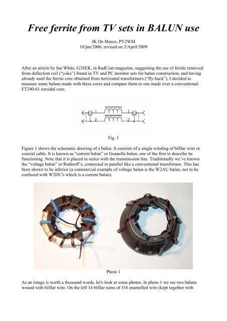
Fig. 1<br />
Figure 1 shows the schematic draw<strong>in</strong>g of a balun. It consists of a s<strong>in</strong>gle w<strong>in</strong>d<strong>in</strong>g of bifilar wire or<br />
coaxial cable. It is known as “current balun” or Guanella balun, one of the first to describe its<br />
function<strong>in</strong>g. Note that it is placed <strong>in</strong> series with the transmission l<strong>in</strong>e. Traditionally we’ve known<br />
the “voltage balun” or Ruthroff’s, connected <strong>in</strong> parallel like a conventional transformer. This has<br />
been shown to be <strong>in</strong>ferior (a commercial example of voltage balun is the W2AU balun, not to be<br />
conf<strong>use</strong>d with W2DU's which is a current balun).<br />
Photo 1<br />
As an image is worth a thousand words, let's look at some photos. In photo 1 we see two baluns<br />
wound with bifilar wire. On the left 14 bifilar turns of #16 enamelled wire (kept together with
pieces of heat-shr<strong>in</strong>k tube). On the right 7 turns over a <strong>ferrite</strong> core <strong>from</strong> a <strong>TV</strong> deflection core, the<br />
halves were glued with cyanocrylate <strong>in</strong>stant glue.<br />
Photo 2<br />
For maximum bandwidth it is <strong>in</strong>terest<strong>in</strong>g to <strong>use</strong> coaxial cable for the w<strong>in</strong>d<strong>in</strong>g as shown <strong>in</strong> photo 2<br />
(beware, it is wired as a transformer). Here I <strong>use</strong>d RG-58 with the outer jacket removed <strong>in</strong> order to<br />
make w<strong>in</strong>d<strong>in</strong>g easier. It should be well protected <strong>from</strong> weather effects. Sevick does not recommend<br />
RG-8X cable s<strong>in</strong>ce the <strong>in</strong>sulation, foamed polyethylene, would not prevent migration of the <strong>in</strong>ner<br />
conductor (and hence short<strong>in</strong>g) due to the small radius of curvature.<br />
I also <strong>in</strong>cluded a balun us<strong>in</strong>g a fly-back core, photo 3.<br />
And now for the measur<strong>in</strong>g results. My set-up consisted of a Yaesu FT840 MF-HF xcvr, a<br />
commercial/modified and calibrated SWR and power meter, a laboratory 50Ω DC-8 GHz<br />
We<strong>in</strong>schel Corp M1426 load, an oscilloscope Tektronix 453, an antenna analyser Autek Research<br />
RF-1 and a homebuilt LC meter (described <strong>in</strong> my website).
1 - INDUCTANCE<br />
TABLE 1 - number of turns and <strong>in</strong>ductance measured <strong>in</strong> LF (about 700 kHz) with the LC meter<br />
FT240-61<br />
Yoke, bifilar Fly-back, bifilar<br />
Yoke, RG-58<br />
wire wire<br />
# turns 14 6 7 10<br />
Inductance 31,6 uH 14 uH 18 uH 99 uH<br />
In table 1 we can see that the fly-back <strong>ferrite</strong> has much more permeability than the others. I<br />
correlated these cores with those found on Fair-Rite catalogue (they are the manufacturers of the<br />
<strong>ferrite</strong> cores sold by Amidon <strong>in</strong> North America). I compared models with similar transversal area.<br />
This is a valuable way to <strong>in</strong>fer the actual permeability.<br />
The yoke core has an <strong>in</strong>termediate permeability between <strong>ferrite</strong> materials 43 and 61, exactly the<br />
most <strong>use</strong>d for transmission l<strong>in</strong>e transformers <strong>in</strong> MF, HF and VHF, this is good news!<br />
The fly-back core looks similar to <strong>ferrite</strong> 77, this is a high permeability but potentially lossy<br />
material.<br />
2 – REACTANCE AND LOSS INTRODUCED WITH WINDING IN PARALLEL TO THE<br />
LOAD<br />
Fig 2<br />
This measurement, shown <strong>in</strong> Figure 2 with results <strong>in</strong> table 2, simulates a balun <strong>in</strong> the worst<br />
situation, when asymmetries <strong>in</strong> the antenna/transmission l<strong>in</strong>e <strong>in</strong>duce currents on the external part of<br />
the transmission l<strong>in</strong>e (<strong>in</strong> case of a coaxial cable). These currents are called “common mode” and<br />
travel on the outer surface of the coaxial cable sheath. The impedance presented by the balun has to<br />
be high enough to impede this current. In this measurement, if the impedance is low the <strong>in</strong>dicated<br />
SWR will be high. All the models did well <strong>in</strong> this test.<br />
TABLE 2 – SWR measur<strong>in</strong>g with w<strong>in</strong>d<strong>in</strong>gs <strong>in</strong> parallel to the load<br />
FT240-61<br />
Yoke, bifilar Fly-back, bifilar<br />
Yoke, RG-58<br />
wire wire<br />
Frequency SWR SWR SWR SWR<br />
1,8 1,05 1,15
3 – USE AS CONVENTIONAL VOLTAGE TRANSFORMER<br />
Fig 3<br />
This measurement, shown <strong>in</strong> Figure 3 with results on table 3, evaluated the performance as a<br />
conventional transformer. The blank cells <strong>in</strong> the table mean no measurements were taken.
TABLE 3 - balun <strong>use</strong>d as conventional voltage transformer<br />
FT240-61 Yoke, RG-58 Yoke, bifilar Fly-back, bifilar<br />
Frequency SWR SWR SWR SWR<br />
1,8 1,15 1,4 1,2
4 – CALCULATED REACTANCE AND MEASURED IMPEDANCE<br />
TABLE 4 - Calculated reactance<br />
FT240-61 Yoke, RG-58 Yoke, bifilar Fly-back, bifilar<br />
Frequency Ohms Ohms Ohms Ohms<br />
1,8 357 158 203 1119<br />
3,5 714 316 406 2238<br />
7 1428 633 813 4476<br />
21 4284 1899 2439 13428<br />
29 5715 2532 3255 17900<br />
TABLE 5 - Impedance, measured<br />
FT240-61 Yoke, RG-58 Yoke, bifilar Fly-back, bifilar<br />
Frequency Ohms Ohms Ohms Ohms<br />
1,8 370 170 1330<br />
3,5 880 346 1080<br />
7 >2000 830 630<br />
21 614 880 286<br />
29 380 490 216<br />
I calculated the reactance us<strong>in</strong>g the <strong>in</strong>ductance value obta<strong>in</strong>ed with the LC meter, table 4. Table 5<br />
shows the impedance measured with an antenna analyser. A simple rule of thumb says the reactance<br />
must be at least 4 or 5 times the impedance of the load/source. Therefore 200 or 250 ohms <strong>in</strong> a 50Ω<br />
system. The yoke core balun would need 1 or 2 more turns to operate on the 160m band. I also took<br />
this balun and made a frequency sweep with the RF-1 antenna analyser while observ<strong>in</strong>g the<br />
impedance and noted a very broad peak of 1440 ohms when the frequency was 13.3 MHz. This is<br />
where a resonance should occur with 10 pF of stray capacitance.<br />
The fly-back balun has too many turns. The impedance decreases with frequency (even though the<br />
<strong>in</strong>ductive reactance <strong>in</strong>creases) beca<strong>use</strong> we are past the resonance frequency and now the impedance<br />
is capacitive. Permeability decreases while losses <strong>in</strong>crease with frequency, complicat<strong>in</strong>g<br />
characterization.<br />
The yoke core is a good substitute for a large toroid core, as <strong>use</strong>d <strong>in</strong> baluns for antennas and antenna<br />
tuners/couplers. With permeability between that of material 43 and 61 it is a perfect choice.<br />
5 – POWER HANDLING<br />
Accord<strong>in</strong>g to measurements made by Sevick, different cores with similar permeability have their<br />
other characteristics also similar. So we can <strong>use</strong> this attribute to determ<strong>in</strong>e power handl<strong>in</strong>g capacity<br />
of unknown cores, compar<strong>in</strong>g to a known type with the same cross sectional area. A good <strong>in</strong>dicator<br />
of power handl<strong>in</strong>g capacity is heat<strong>in</strong>g. If a balun under test suffers a temperature rise then it is<br />
unsuitable.<br />
Fly-back core: this is a high permeability core with high expected dissipative loss. This is only a<br />
problem with high power. Heat<strong>in</strong>g was observed with 100W at 14MHz <strong>in</strong> conventional transformer
<strong>use</strong>. A current balun will be subjected to much less current through its w<strong>in</strong>d<strong>in</strong>g provided a<br />
reasonably matched load exists. Losses <strong>in</strong>crease with frequency.<br />
For conventional transformer to adapt impedances this is a good choice as it requires less turns for a<br />
given <strong>in</strong>ductance. One example would be a Beverage antenna for 160m and/or 80m. Losses must be<br />
evaluated though.<br />
Another good <strong>use</strong> for this type of core is <strong>in</strong> common mode filters for switch<strong>in</strong>g power supplies. In<br />
such a case the loss may come as an asset.<br />
Yoke core: it is expected that a balun with such a core will handle the full legal power. It is<br />
recommended to w<strong>in</strong>d with a suitable coaxial cable capable of this much power. For powers up to<br />
100W a good candidate is RG-174.<br />
Stack<strong>in</strong>g is always a good option to <strong>in</strong>crease power handl<strong>in</strong>g and even the bandwidth as fewer turns<br />
are needed for the same <strong>in</strong>ductance, spurious capacitance is also lower. The <strong>in</strong>ductance is<br />
proportional to the number of cores and to the square of the number of turns. The W2DU balun<br />
consist<strong>in</strong>g of a str<strong>in</strong>g of <strong>ferrite</strong> beads works on this pr<strong>in</strong>ciple, it is a s<strong>in</strong>gle "turn" of coax cable<br />
through a long core.<br />
6 – SOME ADDITIONAL POINTERS<br />
What happens when the core breaks? One of the fly-back cores broke while I was dismantl<strong>in</strong>g it. I<br />
simply glued the parts together with cyanocrylate glue. I compared it to a similar, <strong>in</strong>tact unit which<br />
measured 1.5 uH with a s<strong>in</strong>gle pass of wire, the broken core measured 1 uH. This is the result of the<br />
gap <strong>in</strong>troduced by the glue thickness. I also measured a core with the orig<strong>in</strong>al gap as <strong>use</strong>d <strong>in</strong> the flyback<br />
<strong>TV</strong> transformer, there is a very th<strong>in</strong> (around 0.2 to 0.4 mm) plastic piece between the two<br />
halves, it measured 0.3 uH. See photos 4, 5 and 6.
Photos 7, 8 and 9 show the destruction necessary to reach the core! I also <strong>use</strong>d a Dremel tool to<br />
make some cuts <strong>in</strong> some places; The fly-back transformers are generally filled with a though epoxy<br />
material.
On a later date I managed to discover more <strong>in</strong>formation regard<strong>in</strong>g <strong>ferrite</strong>s employed <strong>in</strong> <strong>TV</strong> <strong>sets</strong>. An<br />
<strong>in</strong>terest<strong>in</strong>g aspect is the resistivity of the materials. High permeability is associated with metallic<br />
MnZn mixtures hav<strong>in</strong>g low resistivity so the core acts as many paralleled resistively shorted turns.<br />
Fly-back core resistivity is only 3 ohm/m. Resistivity is strongly frequency-dependent and<br />
decreases rapidly with frequency <strong>in</strong>crease. Resistivity is expressed <strong>in</strong> ohms per metre units or ohms<br />
per centimetre units, <strong>in</strong> table 6 I have converted all that I have collected <strong>in</strong>to ohms/metre units to<br />
allow direct comparison.<br />
Table 6 – Common <strong>ferrite</strong> materials, their permeability and resistivity<br />
Material Permeability Resistivity<br />
43 800 1x10exp3 ohm/m<br />
61 125 1x10exp6 ohm/m<br />
77 2000 1 ohm/m<br />
Yoke 350 1x10exp5 ohm/m<br />
Fly-back 1800 3 ohm/m<br />
Sab<strong>in</strong>, W0IYH, reported his measurements of three W2DU current baluns, one with 100 beads of<br />
77 material and <strong>in</strong>ductance 100 uH, other with 100 beads of 43 material, <strong>in</strong>ductance 82 uH and<br />
another with 50 larger beads of 43 material for an <strong>in</strong>ductance of 105 uH. He concluded that the high<br />
permeability is good for low HF bands but the other two are better overall and tolerate more power.<br />
He <strong>in</strong>dicates the need of a balun also at the equipment side as a way to reduce pick-up of ho<strong>use</strong>hold<br />
noise.<br />
7 – CONCLUSION<br />
The yoke core is well suited to HF broadband <strong>use</strong> <strong>in</strong> baluns and transformers. The fly-back core is a<br />
high permeability material better suited to low HF. These cores can be found for free <strong>in</strong> repair<br />
shops.<br />
There's much more to discover as one delves <strong>in</strong>to this subject. For the time be<strong>in</strong>g I'm very happy to<br />
report these f<strong>in</strong>d<strong>in</strong>gs and I thank Ian, G3SEK, for his enlighten<strong>in</strong>g RadCom note.<br />
References: Below is a list of what I consider the most <strong>in</strong>formative texts. Some older publications<br />
conta<strong>in</strong> <strong>in</strong>correct <strong>in</strong>formation based on postulates that were demonstrated to be wrong.<br />
"Transmission l<strong>in</strong>e transformers", Jerry Sevick, W2FMI, ARRL, 2001.<br />
"Some aspects of the balun problem", Walter Maxwell, W2DU, QST Mar 1983.<br />
"Some additional aspects of the balun problem", Roehm, W2OBJ, Antenna Compendium 2, ARRL,<br />
1989.<br />
"Baluns: what they do and how they do it", Roy Lewallen, W7EL, Antenna Compendium 1, ARRL,<br />
1985.<br />
"Explor<strong>in</strong>g the 1:1 Current (Choke) Balun", Sab<strong>in</strong>, William E., W0IYH, QEX July 1997.<br />
"Design<strong>in</strong>g wideband transformers for HF and VHF Power Amplifiers", Chris Trask, N7ZWY,<br />
QEX Mar/Apr 2005.
"The 1:1 Current Balun", Roy Lewallen, W7EL: http://eznec.com/misc/ibalun.txt<br />
"Balun Balance Quality Test", Tom Rauch, W8JI: http://www.w8ji.com/Baluns/balun_test.htm<br />
Fair-Rite Technical Information: http://www.fair-rite.com/newfair/pdf/Broadband.pdf<br />
http://www.fdk.co.jp/cyber-e/pi_fer_tv.htm<br />
http://www.magtek.com.cn/SFC.html<br />
Resistivity: http://www.earthsci.unimelb.edu.au/ES304/MODULES/RES/NOTES/resistivity.html