Audio Codec '97 Revision 2.1
Audio Codec '97 Revision 2.1
Audio Codec '97 Revision 2.1

Create successful ePaper yourself
Turn your PDF publications into a flip-book with our unique Google optimized e-Paper software.
AC ‘97 Component Specification <strong>Revision</strong> <strong>2.1</strong><br />
5. Digital Interface<br />
5.1 AC-link Digital Serial Interface Protocol<br />
AC ‘97 incorporates a 5 pin digital serial interface that links it to the AC ’97 Controller. AC-link is a bi-directional,<br />
fixed rate, serial PCM digital stream. It handles multiple input, and output audio streams, as well as control register<br />
accesses employing a time division multiplexed (TDM) scheme. The AC-link architecture divides each audio frame<br />
into 12 outgoing and 12 incoming data streams, each with 20-bit sample resolution. With a minimum required DAC<br />
and ADC resolution of 16-bits, AC ‘97 could also be implemented with 18 or 20-bit DAC/ADC resolution, given<br />
the headroom that the AC-link architecture provides.<br />
The control and data slots defined by AC ‘97 1.0 include:<br />
• SDATA_OUT TAG 1 output slot (0)<br />
• SDATA_IN TAG 1 input slot (0)<br />
• Control (CMD ADDR & DATA) write port 2 output slots (1,2)<br />
• Status (STATUS ADDR & DATA) read port 2 input slots (1,2)<br />
• PCM L & R DAC Playback 2 output slots (3,4)<br />
• PCM L & R ADC Record 2 input slots (3,4)<br />
• Optional Modem Line 1 DAC 1 output slot (5)<br />
• Optional Modem Line 1 ADC 1 input slot (5)<br />
• Optional Dedicated Microphone ADC 1 input slot (6)<br />
The control and data slots defined by AC ‘97 2.0 include:<br />
• Optional 6-channel PCM playback 4 output slots (6,7,8,9)<br />
• Optional Modem Line 2, handset output 2 output slots (10,11)<br />
• Optional Modem Line 2, handset input 2 input slots (10,11)<br />
• Optional Modem IO control 1 output slot (12)<br />
• Optional Modem IO status 1 input slot (12)<br />
SYNC<br />
SDATA_OUT<br />
SDATA_IN<br />
Slot # 0 1 2 3 4 5 6 7 8 9 10 11 12<br />
TAG<br />
<strong>Codec</strong> ID<br />
TAG<br />
CMD<br />
ADDR<br />
STATUS<br />
ADDR<br />
SLOTREQ 3-12<br />
CMD<br />
DATA<br />
STATUS<br />
DATA<br />
PCM<br />
L<br />
PCM<br />
L<br />
PCM<br />
R<br />
PCM<br />
R<br />
LINE 1<br />
DAC<br />
LINE 1<br />
ADC<br />
28<br />
PCM<br />
CENTER<br />
MIC<br />
ADC<br />
PCM<br />
L SURR<br />
RSRVD<br />
PCM<br />
R SURR<br />
PCM<br />
LFE<br />
RSRVD RSRVD<br />
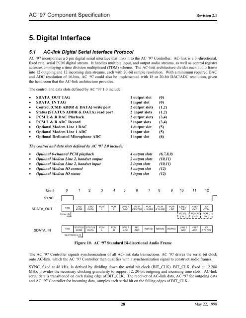
Figure 10. AC ‘97 Standard Bi-directional <strong>Audio</strong> Frame<br />
LINE 2<br />
DAC<br />
PCM L<br />
( n+1)<br />
LINE 2<br />
ADC<br />
HSET<br />
DAC<br />
PCM R<br />
(n+1)<br />
HSET<br />
ADC<br />
IO<br />
CTRL<br />
PCM C<br />
(n+1)<br />
IO<br />
STATUS<br />
The AC ‘97 Controller signals synchronization of all AC-link data transactions. AC ‘97 drives the serial bit clock<br />
onto AC-link, which the AC ’97 Controller then qualifies with a synchronization signal to construct audio frames.<br />
SYNC, fixed at 48 kHz, is derived by dividing down the serial bit clock (BIT_CLK). BIT_CLK, fixed at 12.288<br />
MHz, provides the necessary clocking granularity to support 12, 20-bit outgoing and incoming time slots. AC-link<br />
serial data is transitioned on each rising edge of BIT_CLK. The receiver of AC-link data, AC ‘97 for outgoing data<br />
and AC ’97 Controller for incoming data, samples each serial bit on the falling edges of BIT_CLK.<br />
May 22, 1998