CONTAINMENT - Canteach
CONTAINMENT - Canteach
CONTAINMENT - Canteach

Create successful ePaper yourself
Turn your PDF publications into a flip-book with our unique Google optimized e-Paper software.
Approval Issue<br />
Course 233 -Reactor & Auxiliaries - Module 13 - Containment<br />
b) Loss of Regulation Accident (LORA) with failure to shut down the<br />
reactor quickly enough with subsequent pressure tube failure.<br />
c) Loss of Class IV power with failure to shut down the unit, again,<br />
followed by pressure tube failure.<br />
For events such as (b) and (c), failure of both shutdown systems must<br />
occur (such a combination of failures highly unlikely). Due to failure to<br />
shutdown the reactor, the amOunt of energy released to containment<br />
under these two circumstances would be much higher than that from a<br />
LOCA in which reactor power is terminated by shutdown system<br />
action.<br />
Let us recall, from Module 12, the events following a LOCA into<br />
containment at full power. The Heat Transpon System (HTS) D20 at<br />
high pressure and temperature, will be released, and a portion of it will<br />
flash to steam. The reactor building temperature and pressure will<br />
increase. (Pressure may be above atmospheric for a few minutes,<br />
whereas temperature may rise to as high as 95°C for several hours.)<br />
The containment structure must provide the initial heat sink under these<br />
conditions until alternate long term heat sinks can be made available<br />
(eg. EelS Recovery Heat Exchangers) following EClS operation to<br />
rewet and cool the fuel.<br />
The amount of fission products released will depend on how rapidly the<br />
power pulse was terminated, how the fuel was operating prior to the<br />
LOCA and how well the ECIS has performed When the ECIS is fully<br />
functional and copes with the LOcA. a large number of fuel failures is<br />
unlikely, and the quantity of fission products released will be small.<br />
(Remember, the primary .function of ECIS is to maintain fuel cooling,<br />
which will prevent/minimize fuel failures following a LOCA.) However,<br />
a LOCA can cause tritium releases in the reactor building in the order of<br />
tens of thousands of times the Maximum Pennissible Concentration in<br />
air *(MPCa).<br />
If for any reason ECIS is unable to fully cope with the LOCA, a large<br />
number pf fuel failures are almost certain and a large release of fission<br />
products is to be expected. Higher than normal radiation fields will<br />
occur inside containment.<br />
Containment is basically a structural envelope which contains the<br />
reactor and high pressure components of the HTS. At various locations<br />
interfacing with other systems will occur, ego boilers. The interfacing<br />
depends on how much equipment is located within containment.<br />
In earlier CANDU stations and at 600 MW units, all boilers and HTS<br />
circulating pumps are totally within containment. This -naturally<br />
increases the size of the reactor buildings required to house these<br />
components.<br />
Rev 3<br />
NOTES & REFERENCES<br />
• Recall, from radiation<br />
protection training, that<br />
working in 1 MPCa tritium<br />
concentration for 40<br />
hrs/Wk for 1 year will give<br />
the maximum permissible<br />
armual dose for whole<br />
body exposure.<br />
Page 3
Course 233 -Reactor &; Auxiliaries - Module 13 - Contaimnent<br />
NOTES & REFERENCES<br />
Page 4<br />
Approval Issue<br />
In the case of the older CANDU units, a larger containment structure is<br />
required to accommodate the larger volume of the reactor vaults.<br />
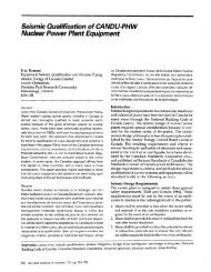
At newer stations, the decision was made, following a detailed safety<br />
study, to relocate various equipment items and thereby reduce the size<br />
of containment required. For example. only the main HT pump bowls<br />
and boiler bases are within containment.· Figure 13.1 below shows the<br />
extension of the HTS beyond the containment boundary.<br />
1+---BoUer<br />
Figure 13.1<br />
Typical Boiler Configuration<br />
The larger containment structure of older stations has areas that have<br />
some accessibility on power (with and without using access control,<br />
depending on the area). This feature is not present at the newer<br />
stations.<br />
Containment effectiveness is determined by the leak rate from the<br />
structure during an accident situation. The basic principle is, therefore,<br />
to eliminate or minimize leaks and, if leakage occurs, it must be in a<br />
controlled manner and monitored. This is one reason why containment<br />
is maintained subatmospheric. Any leakage is inward. An exhaust flow<br />
is m1011ntlo1;ned to keep the pressure subatmospheric. This exhaust is<br />
filtered and monitored.<br />
Rev 3
Approval Issue<br />
Course 233 -Reactor & Auxiliaries - Module 13 - Containment<br />
Note that all containment penetrations (piping, cables, airlocks, transfer<br />
chambers, etc.) have seals to prevent leakage. A periodic pressure test<br />
is also performed to verify containment integrity.<br />
Outleakage will occur if containment pressure is above atmospheric. If<br />
pressure exceeds design limits, containment structural damage can<br />
occur.<br />
TYPES OF <strong>CONTAINMENT</strong><br />
Two types of containment systems are currently employed in CANDU<br />
reactors:<br />
1) Pressure suppression - used in CANDU 600 MW single unit<br />
stations.<br />
2) Negative pressure - used at all Ontario Hydro multi-unit stations.<br />
The effectiveness of both types of containment is dependent upon<br />
having a poised Eel system available to limit the longer term energy<br />
input in the event of a LOCA.<br />
Rev 3<br />
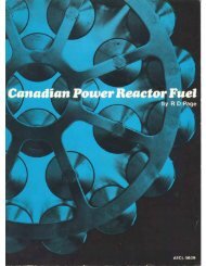
Figure 13.2<br />
Typical Pressure Suppression Containment System<br />
NOTES & REFERENCES<br />
Obj. 13.1<br />
Page S
Course 233 -Reactor & Auxiliaries - Module 13 - Containment<br />
NOTES & REFERENCES<br />
Obi. 13.2 <br />
Obi. 13.3 <br />
Obi. 13.4 <br />
* Recall from Module 12<br />
that a portion of the dousing<br />
water is reserved for<br />
Eel injection.<br />
Obi. 13.5 ¢:><br />
Page 6<br />
PRESSURE SUPPRESSION <strong>CONTAINMENT</strong> (PSC)<br />
Approval Issue<br />
A general schematic of a pressure suppression system is shown in<br />
Figure 13.2 at the bottom of the previous page.<br />
Containment consists of a prestressed concrete structure with a domed<br />
roof. a dousing system, airlocks and a closure system. The concrete<br />
walls are over 1 metre thick.<br />
All internal surfaces of the containment structure, eg, the upper dome,<br />
outer walls, and base slab. the outer surfaces of the irradiated fuel<br />
discharge bay and airlocks normally form part of the containment<br />
boundary (during fuel transfers. the boundary extends to the surfaces of<br />
the irradiated fuel storage bay).<br />
During normal operation, the pressure within containment is<br />
maintained slightly subatmospheric by ventilation system operation.<br />
When. for any reason, the containment pressure increases above<br />
atmospheric, and especially during a LOCA, the leakage from<br />
containment must be limited. The release of tritium and fission products<br />
to the environment is kept below the maximum permissible level by not<br />
exceeding a specified leak rate. For any size of LOCA, the<br />
overpressure should not exceed the limit of -120 kPa(g).<br />
A dousing tank is located in the dome of the containment building. It<br />
holds light water for both dousing (-2000 m 3 ) and medium pressure<br />
emergency coolant injection (-500 m 3)*. Dousing is accomplished<br />
by the opening of the dousing valves. With these valves open. water<br />
flows by gravity from the storage tank to the spray headers to cause<br />
dousing. (These valves are channelized and require a majority vote to<br />
initiate dousing). Dousing condenses the released steam and thus:<br />
1) Absorbs the heat energy in the steam;<br />
2) Reduces the magnitude and duration of the containment<br />
overpressure pulse; <<br />
3) Dissolves soluble fission products (eg, 1 131 ), and entrains<br />
insoluble fission products. minimizing the airborne spread of<br />
contamination.<br />
Note that noble gas fission products, like Krypton 88, will be unaffected<br />
by dousing.<br />
The containment structure is normally cooled and dehumidified by<br />
vault coolers. This is necessary due to sources of heat (HTS piping,<br />
boilers, etc.) and humidity (small leaks of D20t H20) within<br />
containment.<br />
Rev 3
Approval Issue<br />
PSC Button-uplBox-up<br />
Course 233 -Reactor & Auxiliaries - Module 13 • Containment<br />
During a LOCA, the containment structure can be isolated from the<br />
environment by closing tbe isolation points. Ibe isolation points are<br />
dampers at the ventilation penetrations and valves on the piping<br />
penetrations. This is termed "button-up" or "box_up". This is done to<br />
prevent leakage above pennissible levels (as discussed in the previous<br />
section).<br />
Button-Up (Box-Up) is typically initiated by any of the following<br />
signals:<br />
- High containment radioactiVity,<br />
- High containment pressure,<br />
- High exhaust and stack radioactivity or loss of stack monitoring.<br />
Operation of PSC During a Small LOCA<br />
In the case of a small LOCA, the energy release will be smaller but will<br />
likely occur over a longer period. Containment pressure will slowly<br />
increase, and bOX-Up will occur on one or more of the initiating<br />
parameters. The vault coolers may condense the resulting steam (and<br />
limit containment pressure) such that pressure to initiate dousing is not<br />
reached.<br />
If pressure continues to rise to the dousing setpoint (-14 kPa(g», some<br />
intermittent dousing action will occur as the dousing valves open and<br />
close on staggered setpoints, as shown in Figure 13.3.<br />
Under these conditions after the initial period of dousing, which will<br />
cease when pressure falls to the dousing "OFF" setpoint (-7 kPa(g»,<br />
pressure will probably again increase and further dousing cycles may be<br />
required until pressure remains below the uOFF u setpoint. As energy<br />
input from the LOCA falls (due to depressurization of the HTS),<br />
condensation on walls, and vault coolers becomes a major factor in<br />
keeping containment pressure low.<br />
Operation of PSC During a Large LOCA<br />
For a large LOCA containment pressure and temperature increase<br />
rapidly. Containment button-up (and a reactor trip) occurs at a<br />
containment pressure of about 3.5 kPa(g) and dousing commences at<br />
an overpressure of approximately 14 kPa(g).<br />
For a large LOCA, there will be a period of continuous dousing which<br />
will quickly reduce containment pressure towards atmospheric. Further<br />
Rev 3<br />
NOTES & REFERENCES<br />
¢::> Obi. 13.6<br />
¢::> Obi. 13.7 a)<br />
¢::> Obi. 13.5<br />
¢::> Obi. 13.7 b)<br />
Page 7
Approval Issue<br />
Course 233 -Reactor &: Auxiliaries - Module 13 - Containment<br />
One additional note to make here is that the requirement to remove the<br />
steam/air mixture from the reactor vaults requires a clear passage to<br />
the vacuum building. This is why the fuelling machines should not be<br />
parked side by side in the fuelling machine duct (part of the pressure<br />
relief path to the vacuum building). Improper parking of the fuelling<br />
machines with. a LOCA ;n progress con1d restrict steaII'Jair movement,<br />
which would allow pressure on the LOCA side of the fuelling machines<br />
to build up. This could cause damage to the reactor vault due to<br />
overpressurization.<br />
Note that this containment structure Will leak at a higher rate during the<br />
short overpressUA-e during a LCY",.,A. But, tt-Js is ordy short term (ie.<br />
NPC has a higher leak rate for short term versus PSC which has a<br />
lower leak rate, but for a longer time).<br />
Vacuum building<br />
The vacuum building greatly reduces the chance of leaks from the<br />
containment area, by limiting containment overpressure during a LOCA.<br />
Without it. even the short duration overpressure transient (30-60<br />
seconds) in the containment area following a LOCA would result in<br />
unacceptable leakages to the environment<br />
The building is a reinforced concrete structure of sufficient volume to<br />
accommodate all of the air and steam drawn in from the reactor building<br />
and preSSlLT'e relief duct in the event of 1Ln accitipnt.<br />
Note that the upper portion of the vacuum building contains an<br />
emergency water storage tank (see Figure 13.4), which contains water<br />
for both dousing and the EelS (in some stations). This water also<br />
provides the necessary vacuum isolation between the upper and main<br />
chambers plus the water seal in the spray (or dousing) header.<br />
The vacuum building is divided into:<br />
a) Upper Vacuum Chamber<br />
This chamber is isolatecl by watersealing and held at a low<br />
subatmospheric pressure, typically -7 kPa(a), by means of vacuum<br />
pumps located in the vacuum building basement Its main purpose<br />
is to provide a .1P to automatically initiate dousing action<br />
following a LOCA.<br />
b) Main Chamber<br />
Rev 3<br />
This has a much larger volume than the upper chamber (typically<br />
60-70 times larger), and again, is maintained at a pressure of<br />
approximately -7 kPa(a). This pressure is maintained by vacuum<br />
NOTES & REFERENCES<br />
Obi. 13.3<br />
Obi. 13.8 e)<br />
& 13.9 a)<br />
¢:> Obj. 13.8 b)<br />
Obi. 13.8. e)<br />
Page 11
Course 233 -Reactor & Auxiliaries· Module 13 • Containment<br />
NOTES & REFERENCES<br />
• This is discussed on page<br />
18.<br />
Obj. 13.10 b) ¢::><br />
Obj. 13.11 ¢::><br />
Page 16<br />
Approval Issue<br />
the upper chamber with water allows flow over a weir into the outlet<br />
and spray headers, thus initiating dousing into the main chamber. The<br />
spray ofcold H20 into the steam/air mixture (in the main chamber) will<br />
condense the steam. This will reduce pressure as the volume of .the<br />
steam decreases.<br />
Note that, in most stations, the weir design in the upper chamber (as<br />
shown in Fig. 13.4 on page 10) prevents the fonnation of syphon, by<br />
preventing the air in the upper chamber from being carried into the oudet<br />
header. If the air in the upper chamber is lost, a syphon will form. If a<br />
syphon forms during dousing, it will not stop until the tank is empty.<br />
As a result of the pressure decrease during dousing, PRY closure will<br />
occur. PRVs initially, then followed by APRVs and IPRYs.<br />
Containment pressure will then be maintained subatmospheric by the<br />
IPRVs or APRVs and vault coolers, as described earlier. A typical<br />
pressure transient for a large LOCA is shown in Figure 13.6 on the next<br />
page.<br />
In the long term, to retain the containment pressure subatmospheric,<br />
the Ftltered Air Discharge System * is initiated by the operator.<br />
NPC operation during a small LOCA<br />
In this instance, the pressure rise within containment will be smaller,<br />
. and it is likely that the opening pressure of the large PRYs will not be<br />
reached.<br />
The overpressure in containment in this instance will be handled by the<br />
IPRVs or APRVs, depending on the station. When containment<br />
pressure is reduced, the APRVs will close, but will modulate to<br />
maintain containment pressure negative. If the LOCA is small enough,<br />
the opening pressure of any relief valve may not be achieved, and the<br />
increase in pressure and the return to subatmospheric conditions will be<br />
handled by the vault coolers (provided enough steam is condensed).<br />
Dousing during a small LOCA will be dependent upon the pressure rise<br />
in the vacuum building, and, if dousing occurs, it will cycle following<br />
the modulation of the IPRVs or APRVs.<br />
AIRLOCKS<br />
Airlocks arc penetrations in the containment boundary that are provided<br />
to allow the passage of personnel and equipment, without breaching<br />
the containment boundary. This is accomplished by the use of a<br />
double set of doors for each airlock. By having only one door open at<br />
any time, the containment boundary is not breached. Each of the airlock<br />
doors are sealed by using an inflatable seal. Operating procedures and<br />
built in interlocks are used to ensure that the containment boundary is<br />
not breached when airlocks arc used.<br />
Rev 3
Approval Issue<br />
Course 233 -Reactor & Auxiliaries - Module 13 - Containment<br />
• Following a small LOCA, for a NPC system, containment pressure<br />
slowly starts to rise. Box up (or button up) is initiated on one or<br />
more of the initiating parameters. The vault coolers will act to<br />
condense the steam and will cool the vault atmosphere. This may<br />
limit the containment pressure increase to the point where no PRY<br />
action is required. If containment pressure continues to rise, the<br />
APRYs or IPRYs will open to reduce containment pressure. Once<br />
containment pressure is reduced, the APRYs will close, but will<br />
modulate to keep containment pressure below atmospheric.<br />
• Airlocks allow for the passage of personnel and equipment int%ut<br />
of containment without opening containment to atmosphere.<br />
• The filtered air discharge system (FADS) will allow the<br />
contaminated air in the containment or vacuum structure to be<br />
discharged to atmosphere (at a controlled rate) after it is filtered to<br />
remove contaminants. This can maintain containment pressure<br />
subatmospheric.<br />
• The hydrogen ignition system will ignite low concentrations of D2IHz<br />
formed during a LOCA, thus preventing severe containment<br />
damage.<br />
VAULT ATMOSPHERE<br />
Purge driers<br />
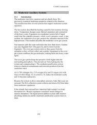
Recall from Module 9 that the purposes of the vapour recovery system<br />
are:<br />
a) Collection and recovery of DzO vapour present in containment as<br />
a result of normal HTS coolant leakage.<br />
b) Removal ofairborne tritium within containment.<br />
c) Maintaining containment pressure slightly subatmospheric.<br />
Point c) is our concern here. After the vapour recovery stage in the<br />
vapour recovery system, air is either returned to containment or<br />
discharged to atmosphere through the purge drlers* and the station<br />
stacks where it is further filtered and monitored by the contaminated<br />
exhaust system. This air now through the purge driers normally<br />
keeps containment pressure subatmospheric (ie. removes the air<br />
that has leaked into containment).<br />
For a PSC system and older stations, a similar purge system to that<br />
mentioned above, maintains the containment DzO areas at a slight<br />
negative pressure, relative to other accessible areas.<br />
Rev 3<br />
NOTES & REFERENCES<br />
Obj. 13.14<br />
... The purge driers are considered<br />
part of the vapour<br />
recovery system.<br />
Page 19
Approval Issue<br />
ASSiGNMENT<br />
Course 233 -Reactor &; Auxiliaries - Module 13 - Containment<br />
1. a) Two types of containment systems used in CANDU stations<br />
are:<br />
i)<br />
b) The poised system is available to limit the long<br />
tenn energy input into containment in the event of a LOCA.<br />
2 The function of an airlock is to provide _<br />
3. Box-up or Button-up occurs by _<br />
___________________, For a NPC<br />
system this also shuts down the _<br />
and the , These<br />
actions occur to '--- _<br />
4. Vault coolers act to:<br />
a) Normally- _<br />
b) During a LOCA- _<br />
s. Dousing systems act as follows:<br />
a)<br />
b)<br />
c)<br />
6. For a NPC system,<br />
a) The upper vacuum chamber maintains a such that<br />
________ will occur automatically when main<br />
vacuum chamber pressure increases,<br />
NOTES & REFERENCES<br />
Rev 3 Page 21
Course 233 -Reactor & Auxiliaries • Module 13 - Containment<br />
NOTES & REFERENCES<br />
Approval Issue<br />
b) The pressure in the vacuum building main chamber is main<br />
tained by the<br />
c) The main vacuum chamber is where will<br />
occur.<br />
d) PRVs normally containment from the vacu-<br />
um building. During a LOCA, in con-<br />
tainment causes these valves to open.<br />
e) The vacuum duct connects to the<br />
___________. This duct allows mainte-<br />
nance on the PRVs by _<br />
f) The pressure relief duct connects the to<br />
the _<br />
g) The vacuum in the upper chamber is maintained by the__<br />
______ seal. Any air inleakage is accommodated by<br />
the -,- _<br />
7. For a NPC system, the dousing mechanism is:<br />
8. For a PSC system, the dousing mechanism is:
Approval Issue<br />
Course 233 -Reactor & Auxiliaries - Module 13 - Containment<br />
9. The purpose of the Filtered Air Discharge System is: _<br />
to. The purpose of the Hydrogen Igniters is: _<br />
11. a) For a PSC system, a small LOCA will cause containment to:<br />
11. b) For a PSC system, a large LOCA will cause containment to:<br />
12. a) For a NPC system, a small LOCA will cause containment to:<br />
NOTES & REFERENCES<br />
Rev 3 Page 23
Course 233 -Reactor & Auxiliaries - Module 13 - Containment<br />
NOTES & REFERENCES<br />
b) Following a large LOCA, for a NPC system, containment<br />
Approval Issue<br />
13. The containment system must be available with the unit at power<br />
because _<br />
_______________. If the containment sys-<br />
tem is to be made unavailable, the units must be _<br />
14. Dousing or emergency storage tank water is for _<br />
and .<br />
15. PSC pressure is normally maintained subatmospheric by the<br />
NPC pressure is normally<br />
maintained subatmospheric by the _<br />
Before you move on, review the objecth,'es and make sure that you<br />
can meet their requirements.<br />
Prepared by: N. Ritter. WNTD<br />
Revised by: P. Bird, WNTD<br />
Revision date: June, 1992<br />
Page 24 Rev 3