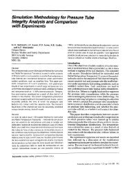
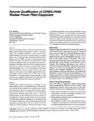
234.00-5 Turbine, Generator & Auxiliaries - Course 234 ... - Canteach
234.00-5 Turbine, Generator & Auxiliaries - Course 234 ... - Canteach
234.00-5 Turbine, Generator & Auxiliaries - Course 234 ... - Canteach

Create successful ePaper yourself
Turn your PDF publications into a flip-book with our unique Google optimized e-Paper software.
<strong><strong>234</strong>.00</strong>-5<br />
<strong>Turbine</strong>, <strong>Generator</strong> & <strong>Auxiliaries</strong> - <strong>Course</strong> <strong>234</strong><br />
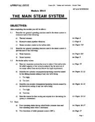
TURBINE GOVERNORS<br />
We have seen in the preceding lesson how a basic governing<br />
system must function to control the stearn supply to a<br />
turbine. This lesson will concentrate on the method by which<br />
two governing systems achieve this control. The two governing<br />
systems we will examine are the mechanical governor (used<br />
on all NGD turbines up through Pickering NGS-A) and the electrical<br />
governor (used on Bruce NGS-A and subsequent units).<br />
Control<br />
Signal<br />
o erator<br />
Input<br />
Control<br />
Relay<br />
Feedback<br />
Basic Governing System<br />
Figure 5.1<br />
Valve<br />
Actuator<br />
Governor<br />
Stearn<br />
Valve<br />
Whatever the type of governor, it must meet certain basic<br />
requirement:<br />
(a) There must be a method for the operator to vary the<br />
"no-load speed" of the turbine (this enables the<br />
operator to shift the position of the governor<br />
speed droop curve):<br />
March 1984 - I -
5.1.<br />
<strong><strong>234</strong>.00</strong>-5<br />
(b) There must be a speed sensor;<br />
(c) There must be a control relay to admit hydraulic<br />
fluid to the governor steam valve power pistons;<br />
(d) There must be a method of feedback from the governor<br />
steam valve position to the control relay;<br />
(e) There must be a method of rapidly closing the governor<br />
steam valves to shut off steam in the event<br />
the generator load is lost;<br />
(f) There must be a method of shutting the governor<br />
steam valves during certain casualties.<br />
The relationship of these components is shown in Figure<br />
Mechanical Governor<br />
Handwheel<br />
Pilot Oil System<br />
Control<br />
Relay<br />
From<br />
Lubricating<br />
Oil System<br />
Pilot Oil<br />
Regulating<br />
Valve<br />
Governor<br />
Steam<br />
Valve<br />
Basic Mechanical - Hydraulic Governing System<br />
Figure 5.2<br />
- 2 -<br />
C
<strong><strong>234</strong>.00</strong>-5<br />
We will now turn our attention to how the governor varies<br />
pilot oil pressure. The method by which the mechanical<br />
governor senses turbine speed is by the position of the Flyballs.<br />
The flyballs are connected to the Governor Piston.<br />
As the governor piston moves, it varies the size of the opening<br />
from the pilot oil system to the governor oil cylinder<br />
(Figure 5.3). If the flyballs move out (speed increasing),<br />
the piston is withdrawn, more oil drains out, the pilot oil<br />
pressure decreases, and the governor steam valve moves in the<br />
shut direction. If the flyballs move in (speed decreasing),<br />
the piston is inserted further into the cylinder, less oil<br />
drains out, the pilot oil pressure increases, and the governor<br />
steam valve moves in the open direction.<br />
In addition to the effect of speed on pilot oil pressure<br />
(via the flyballs and governor piston), the operator can vary<br />
pilot oil pressure through the position of the governor<br />
sleeve. The governor sleeve is moved by the Speeder Gear<br />
which is powered by an electric motor. A control signal<br />
(initiated by the operator or the computer) drives the motor<br />
to move the governor sleeve. This increases or decreases the<br />
size of the drain port, thereby varying pilot oil pressure.<br />
It is important to keep in mind that all the governor<br />
can do is vary pilot oil pressure, and that all varying pilot<br />
oil pressure can do is open or shut the governor steam<br />
valve. The effect produced by varying governor steam valve<br />
position (varying steam flow) is dependent on whether the<br />
generator is synchronized or not synchronized to the grid,<br />
and has nothing to do with the design of the governor. For<br />
example, raising pilot oil pressure will open up on the governor<br />
steam valves and admit more steam to the turbine.<br />
Whether this increases speed or increases load has nothing to<br />
do with the governor but is a function of the external operating<br />
conditions.<br />
You will recall from our discussion of governor operation<br />
in the last lesson that speed droop is a function of the<br />
design of the governor. Figure 5.4 shows a speed droop curve<br />
for a typical large turbine generator.<br />
- 4 -
<strong><strong>234</strong>.00</strong>-5<br />
If a turbine generator with this speed droop is supplying<br />
the Ontario grid system, the grid frequency will not vary<br />
substantially from 60 Hz. This means that, under normal conditions,<br />
the speed of the turbine/generator will remain substantially<br />
at 1800 rpm for a 4 pole generator.<br />
In this case (generator synchronized to an infinite<br />
bus), the effect of increasing steam flow is to increase the<br />
power out of the generator. Since speed cannot change, if<br />
more steam power is put in, more must be supplied by the generator.<br />
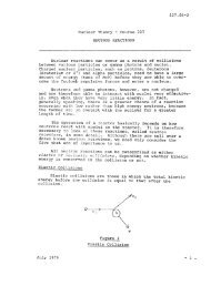
Load Rejection<br />
If the generator output breaker trips open due to an<br />
electrical fault, the speed of the turbine will start to increase.<br />
The flyballs will be thrown outward, withdrawing the<br />
governor piston from the governor oil cylinder. This dumps<br />
pilot oil to drain. As pilot oil pressure is reduced, the<br />
control piston is pushed down under spring tension. This<br />
lowers the spool of the control relay and dumps power oil to<br />
drain. This shuts the governor steam valve.<br />
The mechanical hydraulic governor has two inherent weaknesses<br />
which decreases its ability to handle an overspeed<br />
following load rejection:<br />
1. The dead time associated with the reservoir effect of<br />
low pressure lUbricating oil. The time necessary to<br />
move the large volume of pilot oil and power oil to shut<br />
the governor steam valves, results in excessive overspeeds.<br />
2. When the governor finally gets control of turbine speed,<br />
it will attempt to control speed at the no load speed<br />
determined by the speed droop curve. This no load speed<br />
may be as much as 5% above the normal operating speed.<br />
This means the governor has a built-in bias which works<br />
against holding speed down on a load re jection. Even<br />
though the speeder gear is driven back to the position<br />
corresponding to a no-load speed of 1800 rpm, it cannot<br />
move fast enough to eliminate the effect of speed droop.<br />
One method of attempting to eliminate both of these problems<br />
is the use of an auxiliary governor which operates in<br />
parallel with the main governor. This auxiliary governor has<br />
no speed droop and is set to spill oil at a constant 1% above<br />
normal operating speed. On an overspeed following a load rejection,<br />
the auxiliary governor begins to spill oil at 1%<br />
above operating speed (1818 rpm for an 1800 rpm turbine).<br />
The auxiliary governor not only aids the main governor in<br />
- 7 -
<strong><strong>234</strong>.00</strong>-5<br />
dropping pilot oil pressure but also will attempt to control<br />
speed at 1% overspeed until the speeder gear has run back to<br />
main governor. This effectively eliminates the speed droop<br />
bias of the main governor on an overspeed following load rejection.<br />
In the upper, right hand corner of Figure 5.6 you can<br />
see the main and auxiliary governor of the Pickering NGS turbine.<br />
You can also trace the pilot oil system from the pilot<br />
oil regulating valve to the control relays of each of the<br />
four governor steam valves.<br />
The unfortunate fact about the mechanical hydraulic governor<br />
is that on large turbines, the dead time produced by<br />
reservoir effect in the governing system is unacceptably<br />
long. The main and auxiliary governors together are not capable<br />
of limiting the overspeed following a load rejection to<br />
acceptable levels. To limit the amount of overspeed, the<br />
governing system must be aided by an electric anticipator.<br />
The governor system shown in Figure 5.6 contains two electric<br />
anticipators which operate in parallel. If the generator<br />
output breaker opens under load, the electric anticipators<br />
are tripped by auxiliary contacts on the breaker. The<br />
electric anticipator dumps power oil to drain which shuts the<br />
emergency stop valves. At the same time, the low power oil<br />
pressure, trips pressure switches which shut the intercept<br />
valves and open the release valves.<br />
After five seconds the main and auxiliary governors have<br />
regained control of turbine speed. At this time, the electric<br />
"anticipators reset, and the emergency stop valves and<br />
intercept valves reopen and the release valves shut. The<br />
turbine will thus end up with the steam control valves (ESV,<br />
IV and RV) in their normal position, with the auxiliary governor<br />
controlling turbine speed. As the speeder gear is run<br />
back, the main governor will eventually gain control of the<br />
governor steam valves and lower speed from 101% (auxiliary<br />
governor) to 100% of operating speed. Figure 5.7 shows the<br />
response to a load rejection of a typical mechanical hydraulic<br />
governing system.<br />
- 8 -
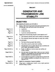
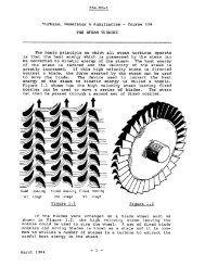
Electrical Governor<br />
Toothed Wheel<br />
Speed Probe<br />
Narrow<br />
Range<br />
Speed<br />
Detector<br />
Variable<br />
Droop<br />
Governor<br />
Steam<br />
Valve<br />
<strong><strong>234</strong>.00</strong>-5<br />
speed/<br />
Load<br />
control<br />
Servo<br />
Ampl.<br />
Basic Electrical-Hydraulic Governing System<br />
Figure 5.8<br />
Basic Electrical - Hydraulic Governor<br />
Servo<br />
Ampl.<br />
Intercept<br />
Valve<br />
Sequence<br />
Figure 5.8 shows a basic electrical governing system.<br />
The turbine speed is sensed through a probe which counts the<br />
teeth passing it on a toothed wheel attached to the shaft.<br />
By calculating the rate at which the teeth pass the probe,<br />
the speed of the turbine can be calculated. The output of<br />
- 11 -
<strong><strong>234</strong>.00</strong>-5<br />
the narrow range speed sensor is fed through the speed droop<br />
control to the servo-amplifiers for the governor steam valves<br />
and intercept valves. A typical servo control system is<br />
shown in Figure 5.9. The intercept valves are sequenced so<br />
as to be fully open any time the governor steam valves are<br />
more than 25% open, and to be 50% open when the governor<br />
steam valves are fUlly shut.<br />
The opening of the governor steam valves and intercept<br />
valves is accomplished through the speed/load control which<br />
is the electrical governing system's equivalent of the speeder<br />
gear. As with the mechanical governor, the input to the<br />
speed/load control may be either manual, computer loading or<br />
runback.<br />
In the mechanical hydraulic governor the speed droop is<br />
a function of the design of the governor, and as such is virtually<br />
a constant. In the electrical governor, however, it<br />
is reasonably easy to vary the speed droop to obtain the most<br />
desirable droop setting for a particular operating condition.<br />
The droop setting is variable between 1% and 12%.<br />
Basically, the droop is high (12%) at operating speed when<br />
not connected to the grid. The droop is moderate (4%) when<br />
at operating speed and synchronized to the grid. The droop<br />
is low (1%) on a load rejection.<br />
Figure 5.10 shows a schematic block diagram of the electrical<br />
hydraulic governing system. The wide range speed detector<br />
is used to control the emergency stop valves during<br />
run up to operating speed. Once at operating speed, the wide<br />
range speed detector plays no role in normal or abnormal<br />
speed control.<br />
Load Rejection<br />
The basic difference between the response of the electrical<br />
hydraulic governor and the mechanical hydraulic governor<br />
on a load rejection, is that the electrical hydraulic<br />
governor is so much faster. Because of the use of electrical<br />
signals and high pressure FRF, dead time is virtually eliminated.<br />
During a full load rejection, the governor can control<br />
the entire overspeed without operation of the emergency stop<br />
valves.<br />
The electrical governing system has two features which<br />
come into operation during a load rejection:<br />
1. An acceleration detector senses the rapid increase in<br />
speed from the narrow range speed detector. This rapid<br />
acceleration initiates a fast valving input which feeds<br />
an overriding signal to the governor steam valves and<br />
intercept valves. Regardless of what other mode the<br />
- 12 -
<strong><strong>234</strong>.00</strong>-5<br />
associated with starting the unit with the generator acting<br />
as an induction motor. The anti-motoring device prevents<br />
closing the output breaker if the emergency stop valves are<br />
shut.<br />
ASSIGNMENT<br />
1. For a mechanical hydraulic governing system, explain the<br />
part the following play in limiting an overspeed following<br />
load rejection:<br />
(a) electric anticipator,<br />
(b) main governor,<br />
(c) auxiliary governor,<br />
(d) speeder gear,<br />
(e) eccentric bolt emergency trip device.<br />
2. For an electrical hydraulic governing system, explain<br />
the part the following play in limiting an overspeed<br />
following load rejection:<br />
(a) narrow range speed detector,<br />
(b) acceleration detector,<br />
(c) variable droop control,<br />
(d) speed/load control,<br />
(e) emergency trip plunger.<br />
3. How is active load varied:<br />
(a) with a mechanical hydraulic governor?<br />
(b) with an electrical hydraulic governor?<br />
4. Explain the advantages of an electrical hydraulic governor<br />
system using FRF over a mechanical hydraulic governor<br />
using lubricating oil.<br />
5. What is the function of the load limiter?<br />
6. What is the function of the anti-motoring device?<br />
R.O. Schuelke<br />
- 19 -