Digital Motor Control Library
Digital Motor Control Library
Digital Motor Control Library

You also want an ePaper? Increase the reach of your titles
YUMPU automatically turns print PDFs into web optimized ePapers that Google loves.
C2000 application<br />
in motor control<br />
and PMSM control demo<br />
Nam, Sang-il<br />
<strong>Digital</strong> <strong>Motor</strong> <strong>Control</strong><br />
SyncWorks Inc.
Agenda<br />
• C2000 Overview<br />
• <strong>Control</strong> Peripherals in C2000<br />
• Brief overview of <strong>Motor</strong> / Machine Theory<br />
• Inverter, C2000 Modules / HW Considerations<br />
• TI DMC Lib. / SW, Algorithm Considerations<br />
• PMSM <strong>Control</strong> Demonstration
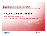
C2000 Overview<br />
Nam, Sang-il<br />
<strong>Digital</strong> <strong>Motor</strong> <strong>Control</strong><br />
SyncWorks Inc.
C2000 Target Applications<br />
Renewable Energy<br />
Generation<br />
Automotive<br />
Radar &<br />
Electric Power<br />
Steering<br />
Consumer & Automotive<br />
<strong>Digital</strong> Power<br />
Telecom <strong>Digital</strong><br />
Power<br />
C2000<br />
AC Drives, Industrial &<br />
Consumer <strong>Motor</strong> <strong>Control</strong><br />
LED Lighting<br />
Power Line<br />
Communications
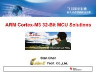
C2000 32-bit MCU Portfolio
TMS320F28xxx Selection Guide<br />
TMS320F281X DSPs<br />
150MHz / 150MMAC<br />
Two Event Managers<br />
Compatible to 240x Devices<br />
12bit ADC, 16 Channels<br />
SPI, SCI, CAN, McBSP<br />
16bit External Interface<br />
√ √<br />
TMS320F280X DSPs<br />
100MHz / 100MMAC<br />
Enhanced PWM Peripherals<br />
Hi-Res. PWM Outputs (150 ps)<br />
Enhanced Capture/QEP Peripherals<br />
12bit ADC, 16 Channels<br />
SPI, SCI, CAN, I 2 C<br />
TMS320F2833X DSPs<br />
150MHz / 150MMAC / 300MFLOPS<br />
C28X + FPU<br />
Enhanced PWM Peripherals<br />
Hi-Res. PWM Outputs (150 ps)<br />
Enhanced Capture/QEP Peripherals<br />
12bit ADC, 16 Channels<br />
6 Channel DMA <strong>Control</strong>ler<br />
SPI, SCI, CAN, I 2 C, McBSP<br />
32bit External Interface
<strong>Control</strong> Peripherals in C2000<br />
Nam, Sang-il<br />
<strong>Digital</strong> <strong>Motor</strong> <strong>Control</strong><br />
SyncWorks Inc.
PWM Peripherals in F281x<br />
• TMS320F281X (Two Event Managers)<br />
EV-A<br />
EV-B<br />
Timer 1<br />
Timer 2<br />
Timer 3<br />
Timer 4<br />
T1PWM<br />
PWM1 ~ PWM6<br />
T2PWM<br />
T3PWM<br />
PWM7 ~ PWM12<br />
T4PWM<br />
Single Phase 4 Channels<br />
Three Phase 2 Pairs (12 Channels)
PWM Peripherals in F280x/F2823x/F2833x<br />
• TMS320F280X/F2833X (Up to 6 Enhanced PWM Modules)<br />
ePWM n<br />
Time-Base<br />
Counter-<br />
Compare<br />
Action-<br />
Qualifier<br />
Event-Trigger<br />
(ePWM1 ~ ePWM6)<br />
PWM-<br />
Chopper<br />
Dead-Band<br />
Trip-Zone<br />
X 6<br />
ePWMnA<br />
ePWMnB<br />
Flexible PWM 12 Channels
Advantage of PWM<br />
in <strong>Digital</strong> <strong>Motor</strong> <strong>Control</strong><br />
• Power Switching Device Limitation<br />
– Difficult to control in proportional region<br />
– Easy to control in saturated region<br />
• PWM signals<br />
– <strong>Digital</strong> signal<br />
– Easy for DSP to output<br />
• PWM “Power DAC”<br />
PWM ENOB (# bit)<br />
PWM System Clock (MHz)<br />
(kHz) 20 30 40 150<br />
10 11.0 11.6 12.0 13.9<br />
20 10.0 10.6 11.0 12.9<br />
30 9.4 10.0 10.4 12.3<br />
50 8.6 9.2 9.6 11.6
Capture / QEP Peripherals<br />
• TMS320F281X<br />
– Use GP-Timers(16bit) in Event Managers<br />
– 6 Capture inputs (Two Capture Module)<br />
• TMS320F280X / F2823X / F2833X<br />
– Use private timer(32bit) in Enhanced Capture Module<br />
– Up to 6 Capture inputs<br />
– APWM Mode<br />
– Absolute Time-stamp Operation<br />
or Delta Operation
ADC Peripherals<br />
• TMS320F281X / F280X / F2823X / F2833X<br />
– Two Sample & Hold / Two Sequencers<br />
– 2 x 8 Channel Input Multiplexer (16 Channels)<br />
– Single / Simultaneous Conversions<br />
– 3.75 ~ 12.50 MSPS<br />
– 0v ~ 3v Input
Brief overview of <strong>Motor</strong> / Machine Theory<br />
Nam, Sang-il<br />
<strong>Digital</strong> <strong>Motor</strong> <strong>Control</strong><br />
SyncWorks Inc.
Application to Three Phases Machine<br />
Operation Fundamentals<br />
1.50<br />
1.00<br />
0.50<br />
0.00<br />
-1.00<br />
-1.50<br />
Three stationary pulsating magnetic fields<br />
C<br />
B`<br />
ia<br />
A`<br />
Fc<br />
Fb<br />
A<br />
Fa<br />
B<br />
C`<br />
Phase currents<br />
ia ib ic<br />
1 24 47 70 93 116 139 162 185 208 231 254 277 300 323 346<br />
-0.50<br />
The three phase winding<br />
produces three magnetic fields,<br />
which are spaced 120° apart<br />
physically.<br />
When excited with three sine<br />
waves that are a 120° apart in<br />
phase, there are three pulsating<br />
magnetic fields.<br />
ωt<br />
• The resultant of the three<br />
magnetic fields is a rotating<br />
magnetic field.
Synchronous <strong>Motor</strong> Operation<br />
C<br />
B`<br />
S<br />
N<br />
S<br />
A`<br />
A<br />
N<br />
B<br />
C`<br />
Rotor field<br />
φ<br />
Stator field<br />
Rotor is carrying a constant magnetic<br />
field created either by permanent<br />
magnets or current fed coils<br />
The interaction between the rotating<br />
stator flux, and the rotor flux produces<br />
a torque which will cause the motor to<br />
rotate.<br />
The rotation of the rotor in this case will be at the same exact frequency as the applied<br />
excitation to the rotor.<br />
This is synchronous operation.<br />
ω<br />
Rotor speed (rad/s) : Ω<br />
= gives<br />
p<br />
f<br />
: AC<br />
p : motor<br />
supply frequency<br />
(Hz)<br />
poles pair per phase<br />
60.<br />
p<br />
f<br />
(r.pm)<br />
Example: a 2 poles pair<br />
synchronous motor will run at<br />
1500 r.pm for a 50Hz AC supply<br />
frequency
Synchronous machine classification:<br />
BLDC and PMSM<br />
Phase A<br />
Hall A<br />
Phase B<br />
Hall B<br />
Phase C<br />
Hall C<br />
C<br />
B`<br />
N<br />
300 900 1500 2100 2700 3300 300 900 600 00 1200 1800 2400 3000 3600 600 i a<br />
Back EMF of BLDC <strong>Motor</strong> Back EMF of BLAC(PMSM)<br />
i b<br />
A`<br />
A<br />
i c<br />
S<br />
B<br />
C`<br />
• Both (typically) have permanent-magnet rotor<br />
and a wound stator<br />
• BLDC (Brushless DC) motor is a permanent-magnet<br />
brushless motor with trapezoidal back EMF<br />
• PMSM (Permanent-magnet synchronous motor) is<br />
a permanent-magnet brushless motor with sinusoidal<br />
back EMF<br />
E a<br />
θ e<br />
θ e<br />
θ e<br />
1.50<br />
1.00<br />
0.50<br />
0.00<br />
1 24 47 70 93 116 139 162 185 208 231 254 277 300 323 346<br />
-0.50<br />
-1.00<br />
-1.50<br />
ea eb ec<br />
ωt
Inverter, C2000 Modules<br />
/ HW Considerations<br />
Nam, Sang-il<br />
<strong>Digital</strong> <strong>Motor</strong> <strong>Control</strong><br />
SyncWorks Inc.
<strong>Motor</strong> <strong>Control</strong> System Overview<br />
TMS320F28X<br />
PWM<br />
ADC<br />
CAP/QEP<br />
6 PWMs<br />
V-dcBus<br />
1A<br />
1B<br />
I L-U I L-V<br />
2A<br />
2B<br />
3A<br />
3B<br />
Current or voltage feedback signals<br />
Sensor signals<br />
V U V V V W<br />
3Phase <strong>Motor</strong><br />
(BLDC or PMSM)<br />
Sensor<br />
(Hall Effect Sensor<br />
or Optical Encoder)<br />
• Event Manager or EPWM<br />
• 3Phase Full-Bridge<br />
• ADC, Capture/QEP
3Ph. BLDC Sensored <strong>Control</strong><br />
TMS320F28X DSC<br />
PWM<br />
Capture<br />
ADC<br />
PWM1<br />
PWM2<br />
PWM3<br />
PWM4<br />
PWM5<br />
PWM6<br />
Hall 1<br />
Hall 2<br />
Hall 3<br />
DC Shunt<br />
Signal<br />
Conditioning<br />
Vdc<br />
PWM1<br />
PWM2<br />
A<br />
DC Shunt<br />
PWM3<br />
PWM4<br />
DC-Bus<br />
B<br />
PWM5<br />
PWM6<br />
C<br />
+<br />
-<br />
3Ph. BLDC<br />
<strong>Motor</strong><br />
Hall 1<br />
Hall 2<br />
Hall 3<br />
0° / 120° / 240°<br />
Commutation / Speed Info.<br />
(Hall Effect Sensor)
3Ph. PMSM Sensored <strong>Control</strong><br />
TMS320F28X DSC<br />
PWM<br />
QEP<br />
ADC<br />
PWM1<br />
PWM2<br />
PWM3<br />
PWM4<br />
PWM5<br />
PWM6<br />
QEP A<br />
QEP B<br />
QEP I<br />
(Optional)<br />
Shunt-1<br />
Shunt-2<br />
Signal<br />
Conditioning<br />
Vdc<br />
PWM1<br />
PWM2<br />
A<br />
Shunt-1<br />
PWM3<br />
PWM4<br />
DC-Bus<br />
B<br />
Shunt-2<br />
PWM5<br />
PWM6<br />
C<br />
+<br />
-<br />
3Ph. PMSM<br />
QEP A<br />
QEP B<br />
QEP I<br />
Position / Speed Info.<br />
(Optical Encoder)
50W - 3phase inverter (SMC75 EVM)<br />
• <strong>Motor</strong> Drive - the Smart Power Module (Fairchild)<br />
• DSC<br />
– 3-phase FRFET inverter including high voltage integrated circuit (HVIC)<br />
– All kinds of TMS320F28X DSC Modules<br />
(SyncWorks)<br />
• Built-in useful circuits<br />
– ADC Signal conditioning circuits<br />
– Circuit for serial interface (CAN, SCI)<br />
– General-Purpose LEDs, Potentiometer, Switches
The C2000 Module Development Platform<br />
One EVM, Multiple C2000 Modules<br />
• TMS320F2812/F2811<br />
• TMS320F2808<br />
• TMS320F28335<br />
C2000 Modules are pin<br />
compatible, allowing<br />
customers to evaluate<br />
multiple C2000<br />
microcontrollers on the<br />
same EVM(baseboard) !
TI DMC Lib. / SW, Algorithm<br />
Considerations<br />
Nam, Sang-il<br />
<strong>Digital</strong> <strong>Motor</strong> <strong>Control</strong><br />
SyncWorks Inc.
TI’s <strong>Digital</strong> <strong>Motor</strong> <strong>Control</strong> <strong>Library</strong><br />
• Useful examples for you<br />
– DC <strong>Motor</strong>, AC Induction <strong>Motor</strong>, BLDC <strong>Motor</strong>, PMSM control<br />
examples<br />
• Just connecting blocks together !
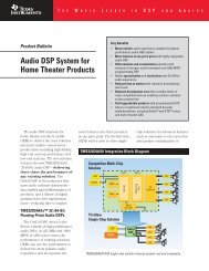
TI’s <strong>Digital</strong> <strong>Motor</strong> <strong>Control</strong> <strong>Library</strong><br />
*Sensored FOC PMSM example block diagram
TI’s <strong>Digital</strong> <strong>Motor</strong> <strong>Control</strong> <strong>Library</strong><br />
• Incremental Build approach<br />
– Incremental system builds reduce development time<br />
Step 1<br />
: Check system vital signs<br />
Step 2<br />
: Check PWM generation<br />
…<br />
Step 6<br />
: Closed loop control
<strong>Motor</strong> <strong>Control</strong> Systems Available<br />
These systems and more can be downloaded<br />
from TI’s website:<br />
• Single Phase Constant V/Hz (ACI)<br />
• 3-Phase Constant V/Hz (ACI)<br />
• 3-Phase Field Oriented <strong>Control</strong> Sensored (ACI)<br />
• 3-Phase Field Oriented <strong>Control</strong> Sensorless (ACI)<br />
• 3-Phase Field Oriented <strong>Control</strong> Sensored (PMSM)<br />
• 3-Phase Field Oriented <strong>Control</strong> Sensorless (PMSM)<br />
• 3-Phase Trapezoidal <strong>Control</strong> Sensored (BLDC)<br />
• 3-Phase Trapezoidal <strong>Control</strong> Sensorless (BLDC)
<strong>Digital</strong> <strong>Motor</strong> <strong>Control</strong> <strong>Library</strong> (DMC-Lib)<br />
The DMC-Lib contains<br />
• PID regulators,<br />
• Clarke transforms,<br />
• Park (& Inverse) transforms,<br />
• Ramp generators,<br />
• Sine generators,<br />
• Space Vector generators,<br />
• Speed / Position meas. / estimators<br />
and more…
PMSM <strong>Control</strong> Demonstration<br />
Nam, Sang-il<br />
<strong>Digital</strong> <strong>Motor</strong> <strong>Control</strong><br />
SyncWorks Inc.
PMSM / BLDC <strong>Control</strong> Demonstration<br />
• PMSM3-4 & BLDC3-1 Examples<br />
– PMSM3-4 : QEP / Field Oriented <strong>Control</strong> (Vector control) / Position PID<br />
– BLDC3-1 : Hall-Sensor / Trapezoidal <strong>Control</strong> / Speed PID<br />
• Hardware environments<br />
– SMC75 & TMS320F28X EVMs<br />
– TMS320F2808 / F2812 Modules<br />
– TDS510USB-C2K JTAG Emulator<br />
– Code Composer Studio v3.3<br />
– DC Power Supply (for DC-Link)<br />
– 15W BLDC <strong>Motor</strong> (DC24V)<br />
– 26W PMSM (DC24V)
PMSM / BLDC <strong>Control</strong> Demonstration<br />
Use TI’s examples in DMC <strong>Library</strong>
Thank you!<br />
www.tms320.co.kr