68-0133 - Y8610U Intermittent Pilot Retrofit Kit - Air & Water
68-0133 - Y8610U Intermittent Pilot Retrofit Kit - Air & Water
68-0133 - Y8610U Intermittent Pilot Retrofit Kit - Air & Water

You also want an ePaper? Increase the reach of your titles
YUMPU automatically turns print PDFs into web optimized ePapers that Google loves.
<strong>Y8610U</strong> INTERMITTENT PILOT RETROFIT KIT<br />
<strong>68</strong>-<strong>0133</strong>—2<br />
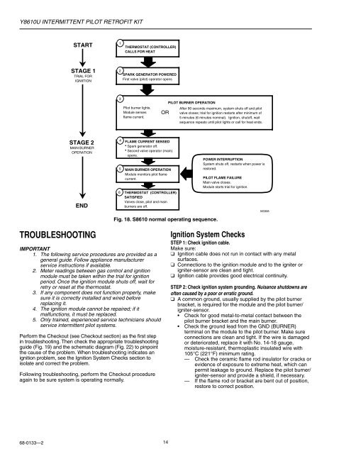
START 1 1<br />
THERMOSTAT (CONTROLLER)<br />
CALLS FOR HEAT<br />
STAGE 1<br />
TRIAL FOR<br />
IGNIITION<br />
STAGE 2<br />
MAIN BURNER<br />
OPERATION<br />
END<br />
TROUBLESHOOTING<br />
SPARK GENERATOR POWERED<br />
First valve (pilot) operator opens<br />
<strong>Pilot</strong> burner lights.<br />
Module senses<br />
flame current.<br />
FLAME CURRENT SENSED<br />
• Spark generator off.<br />
• Second valve operator (main)<br />
opens.<br />
MAIN BURNER OPERATION<br />
Module monitors pilot flame<br />
current.<br />
THERMOSTAT (CONTROLLER)<br />
SATISFIED<br />
Valves close, pilot and main<br />
burners are off.<br />
IMPORTANT<br />
1. The following service procedures are provided as a<br />
general guide. Follow appliance manufacturer<br />
service instructions if available.<br />
2. Meter readings between gas control and ignition<br />
module must be taken within the trial for ignition<br />
period. Once the ignition module shuts off, wait for<br />
retry or reset at the thermostat.<br />
3. If any component does not function properly, make<br />
sure it is correctly installed and wired before<br />
replacing it.<br />
4. The ignition module cannot be repaired; if it<br />
malfunctions, it must be replaced.<br />
5. Only trained, experienced service technicians should<br />
service intermittent pilot systems.<br />
Perform the Checkout (see Checkout section) as the first step<br />
in troubleshooting. Then check the appropriate troubleshooting<br />
guide (Fig. 19) and the schematic diagram (Fig. 22) to pinpoint<br />
the cause of the problem. When troubleshooting indicates an<br />
ignition problem, see the Ignition System Checks section to<br />
isolate and correct the problem.<br />
Following troubleshooting, perform the Checkout procedure<br />
again to be sure system is operating normally.<br />
2<br />
3<br />
4<br />
5<br />
6<br />
OR<br />
Fig. 18. S8610 normal operating sequence.<br />
14<br />
PILOT BURNER OPERATION<br />
After 90 seconds maximum, system shuts off and pilot<br />
valve closes; trial for ignition restarts after minimum of<br />
5 minutes (6 minutes nominal). Ignition, shutoff, wait<br />
sequence repeats until pilot lights or call for heat ends.<br />
POWER INTERRUPTION<br />
System shuts off, restarts when power is<br />
restored.<br />
PILOT FLAME FAILURE<br />
Main valve closes.<br />
Module starts trial for ignition.<br />
M3308<br />
Ignition System Checks<br />
STEP 1: Check ignition cable.<br />
Make sure:<br />
❑ Ignition cable does not run in contact with any metal<br />
surfaces.<br />
❑ Connections to the ignition module and to the igniter or<br />
igniter-sensor are clean and tight.<br />
❑ Ignition cable provides good electrical continuity.<br />
STEP 2: Check ignition system grounding. Nuisance shutdowns are<br />
often caused by a poor or erratic ground.<br />
❑ A common ground, usually supplied by the pilot burner<br />
bracket, is required for the module and the pilot burner/<br />
igniter-sensor.<br />
• Check for good metal-to-metal contact between the<br />
pilot burner bracket and the main burner.<br />
• Check the ground lead from the GND (BURNER)<br />
terminal on the module to the pilot burner. Make sure<br />
connections are clean and tight. If the wire is damaged<br />
or deteriorated, replace it with No. 14-18 gauge,<br />
moisture-resistant, thermoplastic insulated wire with<br />
105°C (221°F) minimum rating.<br />
— Check the ceramic flame rod insulator for cracks or<br />
evidence of exposure to extreme heat, which can<br />
permit leakage to ground. Replace the pilot burner/<br />
igniter-sensor and provide a shield, if necessary.<br />
— If the flame rod or bracket are bent out of position,<br />
restore to correct position.