68-0133 - Y8610U Intermittent Pilot Retrofit Kit - Air & Water
68-0133 - Y8610U Intermittent Pilot Retrofit Kit - Air & Water
68-0133 - Y8610U Intermittent Pilot Retrofit Kit - Air & Water

Create successful ePaper yourself
Turn your PDF publications into a flip-book with our unique Google optimized e-Paper software.
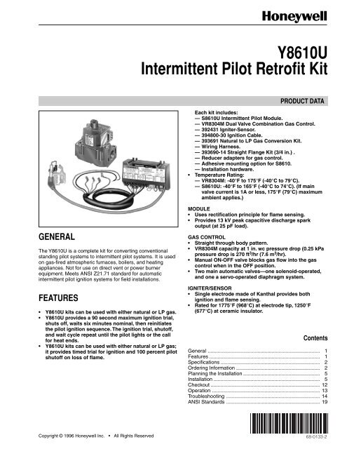
GENERAL<br />
The <strong>Y8610U</strong> is a complete kit for converting conventional<br />
standing pilot systems to intermittent pilot systems. It is used<br />
on gas-fired atmospheric furnaces, boilers, and heating<br />
appliances. Not for use on direct vent or power burner<br />
equipment. Meets ANSI Z21.71 standard for automatic<br />
intermittent pilot ignition systems for field installations.<br />
FEATURES<br />
• <strong>Y8610U</strong> kits can be used with either natural or LP gas.<br />
• <strong>Y8610U</strong> provides a 90 second maximum ignition trial,<br />
shuts off, waits six minutes nominal, then reinitiates<br />
the pilot ignition sequence. The ignition trial, shutoff,<br />
and wait cycle repeat until the pilot lights or the call<br />
for heat ends.<br />
• <strong>Y8610U</strong> kits can be used with either natural or LP gas;<br />
it provides timed trial for ignition and 100 percent pilot<br />
shutoff on loss of flame.<br />
<strong>Y8610U</strong><br />
<strong>Intermittent</strong> <strong>Pilot</strong> <strong>Retrofit</strong> <strong>Kit</strong><br />
PRODUCT DATA<br />
Each kit includes:<br />
— S8610U <strong>Intermittent</strong> <strong>Pilot</strong> Module.<br />
— VR8304M Dual Valve Combination Gas Control.<br />
— 392431 Igniter-Sensor.<br />
— 394800-30 Ignition Cable.<br />
— 393691 Natural to LP Gas Conversion <strong>Kit</strong>.<br />
— Wiring Harness.<br />
— 393690-14 Straight Flange <strong>Kit</strong> (3/4 in.) .<br />
— Reducer adapters for gas control.<br />
— Adhesive mounting option for S8610.<br />
— Installation hardware.<br />
• Temperature Rating:<br />
— VR8304M: -40°F to 175°F (-40°C to 79°C).<br />
— S8610U: -40°F to 165°F (-40°C to 74°C). (If main<br />
valve current is 1A or less, 175°F (79°C) maximum<br />
ambient applies.)<br />
MODULE<br />
• Uses rectification principle for flame sensing.<br />
• Provides 13 kV peak capacitive discharge spark<br />
output (at 25 pF load).<br />
GAS CONTROL<br />
• Straight through body pattern.<br />
• VR8304M capacity at 1 in. wc pressure drop (0.25 kPa<br />
pressure drop is 270 ft 3 /hr (7.6 m 3 /hr).<br />
• Manual ON-OFF valve blocks gas flow into the gas<br />
control when in the OFF position.<br />
• Two main automatic valves—one solenoid-operated,<br />
and one a servo-operated diaphragm system.<br />
IGNITER/SENSOR<br />
• Single electrode made of Kanthal provides both<br />
ignition and flame sensing.<br />
• Rated for 1775°F (9<strong>68</strong>°C) at electrode tip, 1250°F<br />
(677°C) at ceramic insulator.<br />
Contents<br />
General ............................................................................... 1<br />
Features .............................................................................. 1<br />
Specifications ...................................................................... 2<br />
Ordering Information ........................................................... 2<br />
Planning the Installation ...................................................... 5<br />
Installation ........................................................................... 5<br />
Checkout ............................................................................. 12<br />
Operation ............................................................................ 13<br />
Troubleshooting .................................................................. 14<br />
ANSI Standards .................................................................. 19<br />
Copyright © 1996 Honeywell Inc. • All Rights Reserved X-XX UL <strong>68</strong>-<strong>0133</strong>-2
<strong>Y8610U</strong> INTERMITTENT PILOT RETROFIT KIT<br />
SPECIFICATIONS<br />
IMPORTANT<br />
The specifications given in this publication do not<br />
include normal manufacturing tolerances. Therefore,<br />
units might not match the listed specifications<br />
exactly. Also, units are tested and calibrated under<br />
closely controlled conditions, and some minor<br />
differences in performance can be expected if those<br />
conditions are changed.<br />
SUPER TRADELINE® Models<br />
SUPER TRADELINE® models are selected and packaged for<br />
ease of handling, ease of stocking, and maximum replacement<br />
value. SUPER TRADELINE® model specifications are the<br />
same as those of standard models, except as noted.<br />
SUPER TRADELINE® Model Available:<br />
<strong>Y8610U</strong> <strong>Intermittent</strong> <strong>Pilot</strong> <strong>Retrofit</strong> <strong>Kit</strong>:<br />
• Meets ANSI Z21.71 Automatic <strong>Intermittent</strong> <strong>Pilot</strong> Ignition<br />
Systems for Field Installation.<br />
• For natural or LP gas applications.<br />
• 90 second maximum ignition trial, shuts off, waits six<br />
minutes nominal, then reinitiates the pilot ignition<br />
sequence. The ignition trial, shutoff, and wait cycle<br />
repeats until the pilot lights or the call for heat ends.<br />
100 percent pilot shutoff on loss of flame.<br />
• S8610U <strong>Intermittent</strong> <strong>Pilot</strong> Module.<br />
• VR8304M Dual Valve Combination Gas Control.<br />
• Refer to Fig. 1 for other components.<br />
Ambient Temperature Rating:<br />
VR8304M: -40°F to 175°F (-40°C to 79°C).<br />
S8610U: -40°F to 165°F (-40°C to 74°C). (If main valve<br />
current is 1A or less, 175°F (79°C) maximum<br />
ambient applies.)<br />
Also refer to Igniter-Sensor specifications.<br />
Electrical Ratings:<br />
Voltage and Frequency: 20.5 to 28.5 Vac (24 Vac<br />
nominal), 60 Hz.<br />
Current Rating: 0.7A (includes both module and<br />
gas control).<br />
Thermostat Anticipator Setting: 0.7A plus current ratings of<br />
other devices in the thermostat control circuit.<br />
Relative Humidity Rating:<br />
5 to 90 percent at 95°F (35°C).<br />
ORDERING INFORMATION<br />
For ordering information when purchasing replacement and modernization products from your TRADELINE® wholesaler or your<br />
distributor, refer to the TRADELINE® Catalog or price sheets for complete ordering number, or specify:<br />
1. SUPER TRADELINE® order number.<br />
If you have additional questions, need further information, or want to comment on our products or services, please write or<br />
phone:<br />
1. Your local Honeywell Home and Building Control sales office (check white pages of phone directory).<br />
2. Home and Building Control Customer Logistics<br />
Honeywell Inc.,<br />
1885 Douglas Drive North<br />
Minneapolis, Minnesota 55422-4386<br />
In Canada—Honeywell Limited/Honeywell Limitee, 35 Dynamic Drive, Scarborough, Ontario M1V 4Z9.<br />
International Sales and Service Offices in all principal cities of the world. Manufacturing in Australia, Canada, Finland, France,<br />
Germanuy, Japan, Mexicco, Netherlands, Spain, Taiwan, United Kingdom, U.S.A.<br />
<strong>68</strong>-<strong>0133</strong>—2<br />
2<br />
Thermostat Compatibility:<br />
Compatible with any Honeywell 24V thermostat and with<br />
competitive 24V thermostats that are powered independently<br />
of the module.<br />
Transformer Sizing:<br />
Add current ratings of Y8610, vent damper, and any other<br />
control system components. Multiply this total by 24V to<br />
determine the transformer VA requirement.<br />
Wiring Connections:<br />
Between the module and gas control: 30 in. (762 mm)<br />
wiring harness with 1/4 in. quick-connect terminals.<br />
Between the module and the igniter-sensor: 30 in.<br />
(762 mm) ignition cable with stud terminal and 1/4 in.<br />
quick-connect terminal.<br />
<strong>Intermittent</strong> <strong>Pilot</strong> Module Specifications:<br />
S8610U <strong>Intermittent</strong> <strong>Pilot</strong> Module, for natural or LP gas<br />
applications only.<br />
Dimensions:<br />
See Fig. 2.<br />
Flame Failure Response Time:<br />
0.8 second maximum at 1.0 uA flame current.<br />
Ignition Timing:<br />
Provides a 90 second maximum ignition trial, shuts off, waits<br />
six minutes nominal, then reinitiates the pilot ignition<br />
sequence. The ignition trial, shutoff, wait cycle repeats until<br />
the pilot lights or the call for heat ends. During the shutoff<br />
sequence, gas is shut off 100 percent.<br />
Mounting:<br />
Mounts in any position except with terminals up.<br />
Recommended mounting position is with terminals down to<br />
provide maximum protection from dripping water or dust<br />
accumulation. Fasten with No. 6-32 machine screws or No. 8<br />
sheet metal screws of appropriate length. Refer to Fig. 12.<br />
Spark Generator Output:<br />
13 kV peak at 25 pF load (16 kV peak open circuit).<br />
Terminals:<br />
1/4 in. male quick-connects. S8610U has Molex plug for<br />
connection to Honeywell D80D Vent Damper. Once the<br />
S8610U has powered a vent damper, the module works only<br />
if the vent damper is connected.
392431 IGNITER-SENSOR<br />
ASSEMBLY<br />
GROUND<br />
ROD<br />
IGNITER-SENSOR<br />
2 (51)<br />
2-5/8 (67)<br />
VR8304 S8610 INTERMITTENT<br />
PILOT MODULE WITH<br />
WIRING HARNESS<br />
ADAPTER<br />
3-3/16<br />
(81)<br />
ALSO INCLUDED:<br />
3<br />
<strong>Y8610U</strong> INTERMITTENT PILOT RETROFIT KIT<br />
• 394800-30 IGNITION CABLE (30 IN. (760 mm))<br />
• 393690-14 STRAIGHT FLANGE KIT<br />
• 393691 NATURAL GAS TO LP CONVERSION KIT<br />
• REDUCER BUSHINGS FOR GAS CONTROL<br />
• SCREWS<br />
• WIRE NUTS (3)<br />
Fig. 1. Y8610 retrofit kit components.<br />
3-15/16<br />
(100)<br />
3-3/8<br />
(86)<br />
1/4<br />
(6)<br />
1-1/32<br />
(26)<br />
3/16<br />
(5)<br />
(2)<br />
5-7/16 (138)<br />
Fig. 2. S8610U module dimensions.<br />
3-3/8 (86) (2)<br />
3/16<br />
(5)<br />
M<strong>68</strong>66<br />
(2)<br />
M1123A<br />
<strong>68</strong>-<strong>0133</strong>—2
<strong>Y8610U</strong> INTERMITTENT PILOT RETROFIT KIT<br />
Dual Valve Combination Gas Control Specifications<br />
Model:<br />
VR8304M Dual Valve Combination Gas Control.<br />
Ambient Temperature Rating:<br />
-40° to 175°F (-40° to 79°C).<br />
Capacity a :<br />
270 ft 3 /hr (7.6 m 3 /hr) at 1 in. wc (0.25 kPa) pressure drop.<br />
Pipe Size b :<br />
1/2 in. x 3/4 in. NPT inlet x outlet.<br />
a Based on 1,000 Btuh/ft 3 , 0.64 specific gravity natural gas<br />
at 1 in. wc pressure drop (37.3 MJ/m 3 , 0.64 specific gravity<br />
natural gas at 0.25 kPa pressure drop).<br />
b With a 1/2 x 3/4 in. straight flange (included).<br />
Dimensions:<br />
See Fig. 3.<br />
Mounting:<br />
Can be mounted from 0 to 90 degrees, in any direction, from<br />
the gas control upright position.<br />
PRESSURE REGULATOR<br />
ADJUSTMENT<br />
(UNDER CAP SCREW)<br />
INLET<br />
PRESSURE TAP<br />
<strong>68</strong>-<strong>0133</strong>—2<br />
CONVENIENCE<br />
TERMINALS (2)<br />
(OPTIONAL)<br />
WIRING<br />
TERMINALS (3)<br />
OUTLET<br />
PRESSURE<br />
TAP<br />
INLET OUTLET<br />
PILOT OUTLET<br />
GAS PILOT ADJUSTMENT<br />
CONTROL (UNDER CAP SCREW)<br />
RED RESET BUTTON KNOB<br />
M 804A<br />
4<br />
Pressure Rating:<br />
1/2 psig (3.45 kPa) inlet pressure.<br />
Terminals:<br />
1/4 in. male quick-connect terminals.<br />
Igniter-Sensor Specifications<br />
Model:<br />
392431 Igniter-Sensor. Includes igniter-sensor assembly,<br />
ground rod, and adapter (refer to Fig. 1).<br />
Dimensions:<br />
Refer to Fig. 4.<br />
Electrode/Flame Rod Material:<br />
Kanthal.<br />
Maximum Temperature Ratings:<br />
Ground Rod Tip: 1775°F (9<strong>68</strong>°C).<br />
Ceramic Insulator: 1250°F (677°C).<br />
Fig. 3. VR8304M mounting dimensions in in. (mm).<br />
M<strong>68</strong>60<br />
1-1/8 (29)<br />
Mounting:<br />
Replaces the thermocouple on the existing pilot burner.<br />
4-1/16 (104)<br />
Fig. 4. 392431 Igniter-Sensor mounting dimension in in. (mm).<br />
2-3/8<br />
(60)<br />
4 IN. (102) MAX<br />
SWING RADIUS<br />
3-1/2<br />
(89)<br />
1/2<br />
1 (13)<br />
(25)<br />
1/2<br />
(13)<br />
1 (25)<br />
2-11/16 (69)<br />
1/4 INCH<br />
QUICK-CONNECT<br />
TERMINALS<br />
3-15/16<br />
(99)<br />
1-7/16<br />
(36)<br />
M<strong>68</strong>59
PLANNING THE INSTALLATION<br />
<strong>Intermittent</strong> pilot systems are used on various types of central<br />
heating equipment and on heating appliances such as<br />
commercial cookers, agricultural equipment, industrial<br />
heating equipment, and pool heaters. Some of these<br />
applications can make heavy demands on the controls, either<br />
because of frequent cycling or because of moisture, corrosive<br />
chemicals, dust, or excessive heat in the environment. In<br />
these applications, special steps could be required to prevent<br />
nuisance shutdowns and premature control failure. These<br />
applications require Honeywell Home and Building Control<br />
Engineering review; contact your Honeywell Sales<br />
Representative for assistance.<br />
Frequent Cycling<br />
These controls are designed for use on space heating<br />
appliances that typically cycle three to four times an hour<br />
during the heating season and not at all during the cooling<br />
season. In applications with significantly greater cycling rates<br />
and longer heating seasons, we recommend monthly<br />
checkout because the controls can wear out more quickly.<br />
<strong>Water</strong> or Steam Cleaning<br />
Once a module or gas control has been wet, it can operate<br />
unreliably and must be replaced. If the appliance is cleaned<br />
with water or steam, the controls and associated wiring<br />
should be covered so water or steam flow cannot reach them.<br />
The controls should be high enough above the cabinet<br />
bottom so flooding or splashing water can not reach them<br />
during normal cleaning procedures. If necessary, shield the<br />
controls to protect them from splashing water. A NEMA 4<br />
enclosure is recommended for the ignition module; see the<br />
Electronic Ignition Service Manual, form 70-6604.<br />
High Humidity or Dripping <strong>Water</strong><br />
Over time, dripping water or high ambient humidity can create<br />
unwanted electrical paths on the module circuit board,<br />
causing the module to fail. Never install an appliance where<br />
water can drip on the controls.<br />
In addition, high ambient humidity can cause the gas control<br />
to corrode, and finally to fail.<br />
When the appliance is installed in a humid atmosphere, make<br />
sure air circulation around the module and gas control is<br />
adequate to prevent condensation. It is also important to<br />
regularly check out the system. A NEMA 4 enclosure could be<br />
needed; see the Electronic Ignition Service Manual,<br />
form 70-6604.<br />
Corrosive Chemicals<br />
Corrosive chemicals can also attack the module and gas<br />
control and eventually cause a failure. Where chemicals are<br />
used routinely for cleaning, make sure the cleaning solution<br />
cannot reach the controls. Where chemicals could be<br />
suspended in air, as in some industrial and agricultural<br />
applications, protect the ignition module from exposure with a<br />
NEMA 4 enclosure; see the Electronic Ignition Service<br />
Manual, form 70-6604.<br />
Dust or Grease Accumulation<br />
Heavy accumulation of dust or grease can cause the controls<br />
to malfunction. Where dust or grease can cause a problem,<br />
5<br />
<strong>Y8610U</strong> INTERMITTENT PILOT RETROFIT KIT<br />
provide covers for the module and the gas control that emit<br />
environmental contamination. A NEMA 4 enclosure is<br />
recommended for the ignition module; see the Electronic<br />
Ignition Service Manual, form 70-6604.<br />
Heat<br />
The controls can be damaged by excessively high<br />
temperatures. Make sure the maximum ambient temperature<br />
at the control location does not exceed the rating of the<br />
control. If the appliance normally operates at very high<br />
temperatures; insulation, shielding, and air circulation could<br />
be necessary to protect the controls. Proper insulation or<br />
shielding should be provided by the appliance manufacturer;<br />
make sure adequate air circulation is maintained when the<br />
appliance is installed.<br />
INSTALLATION<br />
When Installing this Product…<br />
1. Read these instructions carefully. Failure to follow them<br />
could damage the product or cause a hazardous<br />
condition.<br />
2. Check the ratings given in these instructions and on the<br />
product to ensure the product is suitable for your<br />
application.<br />
3. Installer must be a trained, experienced service<br />
technician.<br />
4. After completing installation, use these instructions to<br />
check product operation.<br />
IMPORTANT<br />
1. Installer must comply with local codes and<br />
ordinances of the National Fuel Code (ANSI<br />
Z223.1—NFPA No. 54) and National Electrical Code<br />
(ANSI NFPA No. 70).<br />
2. Installer must fill in and attach label to appliance<br />
being converted.<br />
3. Use Y8610 <strong>Retrofit</strong> <strong>Kit</strong> only with atmospheric<br />
burners. Do not use on direct vent appliances or<br />
power burners.<br />
4. Do not use the Y8610 <strong>Retrofit</strong> <strong>Kit</strong> with mercury pilots<br />
or 250 to 750 mV pilot systems.<br />
WARNING<br />
FIRE OR EXPLOSION HAZARD<br />
CAN CAUSE PROPERTY DAMAGE,<br />
SEVERE INJURY, OR DEATH.<br />
Follow these warnings exactly:<br />
1. Disconnect the power supply before wiring to<br />
prevent electrical shock or equipment damage.<br />
2. To avoid dangerous accumulation of fuel gas,<br />
turn off gas supply at the appliance service valve<br />
before starting Installation and perform the Gas<br />
Leak Test immediately following the installation.<br />
3. Never install where water can flood, drip, or<br />
condense on module or gas control. Never use a<br />
module or gas control that has been wet. If wet,<br />
controls can malfunction and lead to an<br />
accumulation of explosive gas.<br />
4. Do not light or operate electric switches, lights, or<br />
appliances until you are sure the appliance area<br />
is free of gas. Liquefied petroleum (LP) gas is<br />
heavier than air and does not vent upward<br />
naturally.<br />
<strong>68</strong>-<strong>0133</strong>—2
<strong>Y8610U</strong> INTERMITTENT PILOT RETROFIT KIT<br />
Perform the Preinstallation Safety Inspection<br />
The preinstallation checks described in ANSI Standard<br />
Z21.71 in the ANSI Standards section must be performed<br />
before installing the Y8610. If an unsafe condition is detected,<br />
the appliance should be shut off and the owner advised of the<br />
unsafe condition. Any potentially unsafe condition must be<br />
corrected before proceeding with the Installation.<br />
Maintenance Requirements in Severe Environments<br />
Regular preventive maintenance is important in any<br />
application, but especially in commercial cooking, agricultural,<br />
and industrial applications because:<br />
• In these applications the equipment operates 100,000 to<br />
200,000 cycles per year. Such heavy cycling can wear out<br />
the gas control in one to two years. A normal forced air<br />
furnace (the original application for the controls) typically<br />
operates less than 20,000 cycles per year.<br />
• Exposure to water, dirt, chemicals, and heat can damage<br />
the module or the gas control and shut down the control<br />
system. A NEMA 4 enclosure can reduce exposure to<br />
environmental contaminants. See Electronic Ignition<br />
Service Manual, form 70-6604.<br />
The maintenance program should include regular system<br />
checkout as outlined in the Checkout section.<br />
<strong>68</strong>-<strong>0133</strong>—2<br />
WARNING<br />
FIRE OR EXPLOSION HAZARD<br />
CAN CAUSE PROPERTY DAMAGE,<br />
SEVERE INJURY, OR DEATH.<br />
Do not attempt to disassemble or clean the module.<br />
Improper reassembly and cleaning can cause<br />
unreliable operation.<br />
Maintenance frequency must be determined individually for<br />
each application based on:<br />
• Cycling frequency: Appliances that cycle more than 20,000<br />
times annually should be checked monthly.<br />
• <strong>Intermittent</strong> use: Appliances that are used seasonally<br />
should be checked before shutdown and again before the<br />
next use.<br />
• Consequence of unexpected shutdown: Where the cost of<br />
an unexpected shutdown is high, the system should be<br />
checked more often.<br />
• Dusty, wet, or corrosive environment: Because these<br />
environments can cause the controls to deteriorate more<br />
rapidly, the system should be checked more often.<br />
Any control should be replaced if it does not perform properly<br />
during Checkout or Troubleshooting. In addition, replace any<br />
module if it is wet or looks like it has been wet. Protective<br />
enclosures, see Planning the Installation, are recommended<br />
regardless of checkout frequency.<br />
Shut Down Appliance<br />
Turn off the gas supply at the appliance service valve.<br />
Do not use the gas control knob.<br />
Turn off the electricity at the service entrance.<br />
Check Appliance Wiring<br />
The standing pilot gas control wires are used with the Y8610<br />
kit. Carefully identify and tag the wires before disconnecting.<br />
See Fig. 5 for the most common types of terminal<br />
arrangements.<br />
6<br />
TO<br />
TRANSFORMER<br />
TO<br />
TRANSFORMER<br />
TO<br />
TRANSFORMER<br />
COMMON<br />
COMMON<br />
TO<br />
THERMOSTAT<br />
TO<br />
THERMOSTAT<br />
TO<br />
THERMOSTAT<br />
M<strong>68</strong>58<br />
Fig. 5. Wiring connections on standing pilot gas controls.<br />
Remove Standing <strong>Pilot</strong> Gas Control<br />
If the gas control has a common terminal(s), remove<br />
the wires connected to the common terminal(s) and<br />
splice together with one of the wire nuts provided.<br />
Label and remove the remaining wires.<br />
WARNING<br />
Do not bend the pilot gas tubing at the gas control or<br />
at the pilot burner to prevent gas leakage at the<br />
connection.<br />
Disconnect the pilot tubing at the gas control. Cut off<br />
and discard the compression fitting. Do not disturb the<br />
compression fitting or pilot tubing at the pilot burner.<br />
Disconnect the thermocouple lead at the gas control.<br />
Disconnect the gas piping at the gas control.<br />
Discard the gas control.<br />
Remove Thermocouple<br />
Unscrew or snap the thermocouple out of the pilot burner and<br />
discard. See Fig. 6.<br />
NOTE: It could be necessary to pull out the main burner for<br />
access to the pilot burner. Do not move or relocate the<br />
pilot burner. Do not bend tubing near the pilot burner.<br />
PILOT<br />
BURNER<br />
PILOT<br />
TUBING<br />
REMOVE<br />
THERMOCOUPLE<br />
M<strong>68</strong>62<br />
Fig. 6. Remove thermocouple from pilot burner.
Install Igniter-Sensor Assembly<br />
Install the ground rod, if needed. See Fig. 7.<br />
• Mount adapter to the ground rod, if needed.<br />
• Align the ground rod so the clip hugs the pilot burner<br />
and keeps the ground rod from rotating. See Fig. 8.<br />
• Insert the ground rod in place of the thermocouple<br />
on the pilot burner. Push the ground rod all the way<br />
up and fasten as shown in Fig. 7.<br />
Slide the igniter-sensor mounting bracket over the top<br />
of the ground rod.<br />
Adjust the electrode position so the electrode tip and<br />
spark gas are in the pilot flame. Turn the ground rod to<br />
move the igniter-sensor up and down.<br />
Check that the chosen position allows room to connect<br />
the ignition cable to the stud terminal.<br />
Tighten the setscrews on the mounting bracket using<br />
the hex wrench provided.<br />
SCREW-IN TYPE CLAMP TYPE PUSH-IN TYPE<br />
ADD ADAPTER,<br />
INSERT GROUND<br />
ROD IN PILOT<br />
TIGHTEN NUT<br />
SLIP NUT OFF ADAPTER<br />
AND CLAMP GROUND ROD<br />
IN PILOT WITH SHOULDER<br />
ABOVE CLAMP AS SHOWN<br />
BE SURE THE GROUND CLIP IS SNAPPED ONTO THE PILOT BURNER OR ITS GAS LINE.<br />
Fig. 7. Mount ground rod on pilot burner.<br />
ELECTRODE<br />
GAP<br />
MOUNTING<br />
BRACKET<br />
PILOT<br />
BURNER<br />
GROUND<br />
ROD CLIP<br />
PILOT GAS<br />
TUBING<br />
INSERT<br />
GROUND ROD<br />
GROUND ROD<br />
ELECTRODE<br />
ELECTRODE<br />
SETSCREW (2)<br />
IGNITER-SENSOR<br />
STUD TERMINAL<br />
M<strong>68</strong>63<br />
Fig. 8. Fasten igniter-sensor to ground rod.<br />
M<strong>68</strong>65<br />
7<br />
<strong>Y8610U</strong> INTERMITTENT PILOT RETROFIT KIT<br />
Install the Gas Control<br />
WARNING<br />
FIRE OR EXPLOSION HAZARD<br />
CAN CAUSE PROPERTY DAMAGE,<br />
SEVERE INJURY, OR DEATH.<br />
Follow these warnings exactly:<br />
1. Do not bend the pilot gas tubing at the gas<br />
control or at the pilot burner after the<br />
compression fitting is tightened. Gas leakage at<br />
the connection can result.<br />
2. Always install a sediment trap in the gas supply<br />
line to prevent contamination of the gas control.<br />
3. Do not force the gas control knob. Use only your<br />
hand to turn the gas control knob. If the gas<br />
control knob does not operate by hand, the gas<br />
control should be replaced by a qualified service<br />
technician. Force or attempted repair can result in<br />
a fire or explosion.<br />
IMPORTANT<br />
These gas controls are shipped with protective seals<br />
over the inlet and outlet tappings. Do not remove the<br />
seals until ready to connect the piping.<br />
Converting Between Natural and LP Gas<br />
WARNING<br />
FIRE OR EXPLOSION HAZARD<br />
CAN CAUSE PROPERTY DAMAGE,<br />
SEVERE INJURY, OR DEATH.<br />
1. Do not attempt to use a gas control set for natural<br />
gas on LP gas or a gas control set for LP gas on<br />
natural gas.<br />
2. When making a conversion, main and pilot burner<br />
orifices must be changed to meet appliance<br />
manufacturer specifications.<br />
To convert from natural gas to LP, use the 393691 LP<br />
Conversion <strong>Kit</strong> that is included with the <strong>Y8610U</strong> <strong>Intermittent</strong><br />
<strong>Pilot</strong> <strong>Retrofit</strong> <strong>Kit</strong>. To convert from LP to natural gas, use the<br />
394588 Natural Gas Conversion <strong>Kit</strong> (ordered separately).<br />
Step-opening gas controls cannot be converted.<br />
To convert control from one gas to another:<br />
Turn off the main gas supply to the appliance.<br />
Remove the regulator cap screw and pressure<br />
regulator adjusting screw. See Fig. 3.<br />
Remove the existing spring.<br />
Insert the replacement spring with the tapered end<br />
down. See Fig. 9.<br />
Install the new plastic pressure regulator adjustment<br />
screw so that the top of the screw is flush (level) with<br />
the top of the regulator. Turn the pressure regulator<br />
adjustment screw clockwise six complete turns. This<br />
provides a preliminary pressure setting of about 10.0 in.<br />
wc (2.5 kPa) for LP regulator and 3.5 in. wc (0.9 kPa)<br />
for natural gas regulator.<br />
Check the regulator setting either with a manometer or<br />
by clocking the gas meter. See the Checkout section.<br />
Install the new cap screw.<br />
Mount the conversion label on the control.<br />
Install the control and appliance according to the<br />
appliance manufacturer instructions.<br />
<strong>68</strong>-<strong>0133</strong>—2
<strong>Y8610U</strong> INTERMITTENT PILOT RETROFIT KIT<br />
Install Adapters to Gas Control (if used)<br />
393690-14 Straight Flange (3/4 in.)<br />
Remove the seal over the gas control inlet or outlet.<br />
Make sure that the O-ring is fitted in the flange groove.<br />
If the O-ring is not attached or missing, do not use<br />
the flange.<br />
With the O-ring facing the gas control, align the gas<br />
control threaded holes with the flange clearance holes.<br />
Insert and tighten the screws provided with the flange.<br />
Tighten the screws to 25 inch pounds of torque to<br />
provide a gas tight seal.<br />
Bushings<br />
Remove the seal over the gas control inlet or outlet.<br />
Apply a moderate amount of good quality pipe<br />
compound to the bushing, leaving the two end threads<br />
bare. For an LP installation, use a compound resistant<br />
to LP gas. Do not use Teflon tape.<br />
Insert the bushing in the gas control and thread the<br />
pipe carefully into the bushing until tight.<br />
<strong>68</strong>-<strong>0133</strong>—2<br />
COLOR CODE FOR<br />
LP<br />
GAS<br />
NATRUAL<br />
GAS<br />
CAP SCREW<br />
PRESSURE<br />
BLACK SILVER<br />
REGULATOR<br />
ADJUSTING<br />
SCREW<br />
WHITE WHITE<br />
SPRING RED<br />
STAINLESS<br />
STEEL<br />
PRESSURE<br />
REGULATOR<br />
HOUSING<br />
Fig. 9. Installation of conversion kit<br />
in regulated gas control.<br />
M8083<br />
Install Gas Control Piping<br />
All pipe must comply with local codes and ordinances or with<br />
the National Fuel Code (ANSI Z223.1 NFPA No. 54),<br />
whichever applies. Tubing installation must comply with<br />
approved standards and practices.<br />
Use new, properly reamed pipe free from chips. If<br />
tubing is used, ensure that ends are square, deburred,<br />
and clean. All tubing bends must be smooth and<br />
without deformation.<br />
Run the new pipe or tubing to the gas control. When<br />
tubing is used, obtain a tube-to-pipe coupling to<br />
connect the tubing to the gas control.<br />
Install a sediment trap in the gas supply line. See Fig. 10.<br />
8<br />
HORIZONTAL<br />
3 IN.<br />
(76 MM)<br />
MINIMUM<br />
DROP<br />
DROP<br />
HORIZONTAL<br />
RISER<br />
3 IN.<br />
(76 MM)<br />
MINIMUM<br />
1<br />
1<br />
2<br />
PIPED<br />
GAS<br />
SUPPLY<br />
2<br />
GAS<br />
CONTROL<br />
TUBING<br />
GAS<br />
SUPPLY<br />
GAS<br />
CONTROL<br />
RISER<br />
Fig. 10. Install sediment trap.<br />
PIPED<br />
GAS<br />
SUPPLY<br />
3 IN.<br />
(76 MM)<br />
MINIMUM<br />
ALL BENDS IN METALLIC TUBING SHOULD BE SMOOTH.<br />
Mount Gas Control<br />
The gas control can be mounted from 0 to 90 degrees,<br />
in any direction including vertically, from the upright<br />
position of the gas control knob.<br />
Mount the gas control so the gas flow is in same<br />
direction as the arrow on the gas control bottom.<br />
Thread the pipe as listed in Table 1.<br />
NOTE: See Table 1 for maximum pipe threading<br />
depth. If the pipe is inserted too deeply into<br />
the gas control, the second main valve or<br />
safety valve can distort or malfunction.<br />
Table 1. NPT pipe thread length (in.).<br />
2<br />
GAS<br />
CONTROL<br />
2 CAUTION: SHUT OFF THE MAIN GAS SUPPLY BEFORE REMOVING<br />
END CAP TO PREVENT GAS FROM FILLING THE WORK AREA. TEST<br />
FOR GAS LEAKAGE WHEN INSTALLATION IS COMPLETE.<br />
M3077<br />
Pipe<br />
Size<br />
Overall<br />
Thread Length<br />
Maximum Depth Pipe Can Be<br />
Inserted Into Gas Control<br />
3/8 9/16 3/8<br />
1/2 3/4 1/2<br />
3/4 13/16 3/4<br />
Apply a moderate amount of good quality pipe<br />
compound to pipe only; leave the two end threads bare.<br />
Do not use teflon tape. In LP installations, use a<br />
compound resistant to LP gas. See Fig. 11.<br />
Remove protective seals over the gas control inlet and<br />
outlet, if necessary.
TWO IMPERFECT<br />
THREADS GAS CONTROL<br />
PIPE<br />
THREAD PIPE CORRECT LENGTH APPLY A MODERATE AMOUNT OF<br />
PIPE COMPOUND TO PIPE ONLY<br />
(LEAVE TWO END THREADS BARE).<br />
M3312<br />
Fig. 11. Use moderate amount of pipe compound.<br />
Connect the pipe to the gas control inlet and outlet.<br />
Tighten the inlet and outlet connections using a wrench<br />
on the gas control projecting wrench boss. See Fig. 3.<br />
Connect <strong>Pilot</strong> Gas Tubing<br />
Cut the pilot gas tubing and bend as necessary for<br />
routing to the pilot burner.<br />
• Do not make sharp bends or deform the tubing.<br />
• Do not bend the tubing at the gas control after the<br />
compression nut has been tightened; gas leakage at<br />
the connection can result.<br />
Square off and remove the burrs from the tubing end.<br />
Unscrew the brass compression fitting from pilot gas<br />
outlet (see Fig. 3). Slip the fitting over the pilot gas<br />
tubing and slide out of the way.<br />
NOTE: When replacing a gas control, cut off the old<br />
compression fitting and replace with the new<br />
compression fitting provided on the new gas<br />
control. Never use the old compression fitting<br />
as it might not provide a gas tight seal. See<br />
Fig. 12.<br />
Push pilot gas tubing into the pilot gas tapping until it<br />
bottoms. While holding the tubing all the way in, slide<br />
the compression fitting into place and engage threads.<br />
Turn the fitting until finger tight. Use a wrench to tighten<br />
one more turn. Do not overtighten.<br />
Connect other end of the pilot gas tubing to the pilot<br />
burner according to pilot burner manufacturer<br />
instructions.<br />
GAS CONTROL<br />
TIGHTEN NUT ONE TURN<br />
BEYOND FINGER TIGHT<br />
FITTING BREAKS OFF AND CLINCHES<br />
TUBING AS NUT IS TIGHTENED<br />
Fig. 12. Always use new compression fitting.<br />
PILOT<br />
TUBING<br />
M<strong>68</strong><strong>68</strong><br />
Mounting S8610U <strong>Intermittent</strong> <strong>Pilot</strong> Module<br />
Select a location close to the pilot burner to allow the ignition<br />
cable to run to the igniter-sensor. The ambient temperature<br />
and other conditions should match those listed in the<br />
Specifications.<br />
We recommend mounting the module with the terminals down<br />
so the terminals are protected from dripping water and dust. It<br />
can also be mounted with the terminals on either side. Do not<br />
mount the module with the terminals pointing up. See Fig. 13<br />
for mounting recommendations. Fasten the module securely<br />
with four No. 6-32 machine screws or No. 8 sheetmetal<br />
screws of appropriate length.<br />
9<br />
<strong>Y8610U</strong> INTERMITTENT PILOT RETROFIT KIT<br />
MOUNT IN ONE OF THESE POSITIONS<br />
Fig. 13. S8610 mounting recommendations.<br />
Wiring the System<br />
TERMINALS FACING DOWN<br />
TERMINALS FACING LEFT TERMINALS FACING RIGHT<br />
DO NOT MOUNT<br />
WITH TERMINALS FACING UP<br />
M2647<br />
CAUTION<br />
Disconnect the power supply before making wiring<br />
connections to prevent electrical shock or equipment<br />
damage.<br />
Connect the Ignition Cable<br />
Connect one end of the ignition cable to the male quickconnect<br />
SPARK terminal on the S8610 Module.<br />
Connect the other ignition cable end to the 392431<br />
Igniter-Sensor.<br />
Connect the Vent Damper<br />
The D80D Vent Damper can be used with all ignition modules,<br />
although the Molex plug provided on some modules simplifies<br />
wiring connections when used with the D80D Plug-in Vent<br />
Damper. Once a module with a vent damper plug has powered<br />
a vent damper circuit, it cannot be used in a gas system without<br />
a vent damper. A non-replaceable fuse in the module blows on<br />
<strong>68</strong>-<strong>0133</strong>—2
<strong>Y8610U</strong> INTERMITTENT PILOT RETROFIT KIT<br />
initial power-up. Once this fuse has blown, the module does not<br />
work unless the vent damper is connected.<br />
To connect the plug-in vent damper:<br />
Remove and discard the vent damper plug from the<br />
module terminal strip.<br />
Using the wiring harness supplied, insert the matching<br />
pin plug into the receptacle on the module and the<br />
other end to the vent damper.<br />
To connect the D80B Vent Damper, follow the wiring<br />
diagrams supplied with the vent damper.<br />
Connect S8610 Module<br />
Connect the gas control and other remaining system<br />
components to the ignition module terminals as shown<br />
in Fig. 14 through 16:<br />
• Fig. 14 shows a basic circuit for a heating only<br />
atmospheric burner system.<br />
• Fig. 15 shows a heating only atmospheric burner<br />
system with a D80D Vent Damper.<br />
• Fig. 16 shows a heating only system with a D80B<br />
Vent Damper.<br />
<strong>68</strong>-<strong>0133</strong>—2<br />
PV<br />
PV/MV<br />
MV<br />
VR8304M<br />
COMBINATION<br />
GAS CONTROL<br />
PILOT<br />
BURNER<br />
GROUND<br />
1<br />
2<br />
3<br />
4<br />
MV MV/PV PV<br />
GND<br />
(BURNER)<br />
IGNITER<br />
SENSOR<br />
10<br />
S8610U<br />
24V<br />
VENT<br />
DAMPER<br />
GND 24V TH-W PLUG SENSE SPARK<br />
3<br />
THERMOSTAT<br />
2<br />
LIMIT<br />
CONTROLLER<br />
4<br />
L1<br />
(HOT)<br />
L2<br />
POWER SUPPLY. PROVIDE DISCONNECT MEANS AND OVERLOAD PROTECTION AS REQUIRED.<br />
ALTERNATE LIMIT CONTROLLER LOCATION.<br />
CONTROLS IN 24V CIRCUIT MUST NOT BE IN GROUND LEG TO TRANSFORMER.<br />
JUMPER WIRE FROM CIRCUIT BOARD TO SENSE CONNECTOR REMAINS IN PLACE.<br />
Adjust the thermostat heat anticipator to match the<br />
system current draw. The current draw equals the total<br />
current required for the ignition module (0.2A) plus the<br />
gas control and any other auxiliary equipment in the<br />
control circuit.<br />
Connect Ground Control System<br />
The igniter, flame sensor, and ignition module must share a<br />
common ground with the main burner.<br />
Connect the ground wire with the female 1/4 in. quickconnect<br />
terminal to the male quick-connect GND<br />
(BURNER) terminal on the ignition module.<br />
Strip the other end of the wire and fasten it under the<br />
igniter bracket mounting screw. If necessary, use a<br />
shield to protect the ground wire from radiant heat.<br />
The burner serves as the common grounding area. If<br />
there is not a good metal-to-metal contact between<br />
burner and ground, run a lead from the burner to ground.<br />
NOTE: Earth ground is not required.<br />
Fig. 14. Y8610 in typical atmospheric burner heating system.<br />
1<br />
M<strong>68</strong>61
PV<br />
PV/MV<br />
MV<br />
VR8304M<br />
COMBINATION<br />
GAS CONTROL<br />
1<br />
2<br />
PILOT<br />
BURNER<br />
GROUND<br />
MV MV/PV PV<br />
GND<br />
(BURNER)<br />
IGNITER<br />
SENSOR<br />
11<br />
<strong>Y8610U</strong> INTERMITTENT PILOT RETROFIT KIT<br />
S8610U<br />
4 VENT<br />
24V<br />
DAMPER<br />
GND 24V TH-W PLUG SENSE SPARK<br />
5<br />
WIRING<br />
HARNESS<br />
L1<br />
(HOT)<br />
L2<br />
1<br />
3 CONTROLS IN 24V CIRCUIT MUST NOT BE IN GROUND LEG TO TRANSFORMER.<br />
4 REMOVE PLUG ONLY IF USING VENT DAMPER. FUSE BLOWS ON STARTUP WHEN PLUG IS REMOVED AND VENT<br />
DAMPER WIRING HARNESS IS INSTALLED; THEN MODULE OPERATES ONLY WHEN VENT DAMPER IS CONNECTED.<br />
5 JUMPER WIRE FROM CIRCUIT BOARD TO SENSE CONNECTOR REMAINS IN PLACE.<br />
M3274<br />
Fig. 15. Y8610 in typical atmospheric burner heating system with D80D Vent Damper.<br />
PILOT<br />
BURNER<br />
GROUND<br />
PV<br />
PV/MV<br />
MV<br />
VR8304M<br />
COMBINATION<br />
GAS CONTROL<br />
3<br />
THERMOSTAT<br />
2<br />
LIMIT<br />
CONTROLLER<br />
POWER SUPPLY. PROVIDE DISCONNECT MEANS AND OVERLOAD PROTECTION AS REQUIRED.<br />
ALTERNATE LIMIT CONTROLLER LOCATION.<br />
1<br />
2<br />
3<br />
4<br />
5<br />
6<br />
IGNITER<br />
SENSOR<br />
1<br />
L2<br />
MV MV/PV PV<br />
L1<br />
(HOT)<br />
GND<br />
(BURNER)<br />
LIMIT 2<br />
CONTROLLER<br />
3<br />
TRANSFORMER<br />
S8610U<br />
D80D VENT<br />
DAMPER<br />
4 VENT<br />
24V<br />
DAMPER<br />
GND 24V TH-W PLUG SENSE SPARK<br />
Fig. 16. Y8610 in typical atmospheric burner heating system with D80B Vent Damper.<br />
BLACK<br />
5<br />
4<br />
END SWITCH<br />
N. O. N. C.<br />
LIMIT<br />
CONTROLLER<br />
POWER SUPPLY. PROVIDE DISCONNECT MEANS AND OVERLOAD PROTECTION AS REQUIRED.<br />
ALTERNATE LIMIT CONTROLLER LOCATION.<br />
CONTROLS IN 24V CIRCUIT MUST NOT BE IN GROUND LEG TO TRANSFORMER.<br />
CONNECT VENT DAMPER TERMINAL 1 TO TH-W. LEAVE 24V OPEN. DO NOT REMOVE VENT DAMPER PLUG.<br />
COLORS REFER TO WIRE HARNESS, IF USED.<br />
JUMPER WIRE FROM CIRCUIT BOARD TO SENSE CONNECTOR REMAINS IN PLACE.<br />
MOTOR<br />
ORANGE<br />
D80B<br />
1K2<br />
1K3 1K<br />
RED<br />
1K1<br />
1 2 3 4 5<br />
6<br />
R<br />
YELLOW<br />
THERMOSTAT<br />
OR<br />
CONTROLLER<br />
BLUE<br />
M3310<br />
<strong>68</strong>-<strong>0133</strong>—2
<strong>Y8610U</strong> INTERMITTENT PILOT RETROFIT KIT<br />
CHECKOUT<br />
Check out the gas control system:<br />
• At initial appliance installation.<br />
• As part of regular maintenance procedures. Maintenance<br />
intervals are determined by the application. See Planning<br />
the Installation section for more information.<br />
• As the first Troubleshooting step.<br />
• Anytime work is done on the system.<br />
<strong>68</strong>-<strong>0133</strong>—2<br />
WARNING<br />
FIRE OR EXPLOSION HAZARD<br />
CAN CAUSE PROPERTY DAMAGE,<br />
SEVERE INJURY, OR DEATH.<br />
1. If you smell gas or suspect a gas leak, turn off the<br />
gas at the manual service valve and evacuate the<br />
building. Do not try to light any appliance and do<br />
not touch any electrical switch or telephone in the<br />
building until no spilled gas remains.<br />
2. Perform the Gas Leak Test after initial Installation<br />
and anytime work is done to the gas piping.<br />
STEP 1: Perform a Visual Inspection.<br />
• With the power off, make sure all wiring connections are<br />
clean and tight.<br />
• Turn off all power to appliances and the ignition module.<br />
• Open manual shutoff valves in the gas line to the<br />
appliance.<br />
• Perform Gas Leak Test.<br />
WARNING<br />
FIRE OR EXPLOSION HAZARD<br />
CAN CAUSE PROPERTY DAMAGE,<br />
SEVERE INJURY, OR DEATH.<br />
Check for gas leaks with soap and water solution<br />
anytime work is done on a gas control.<br />
Gas Leak Test<br />
Paint all pipe connections upstream of the gas control<br />
with a rich soap and water solution. Bubbles indicate a<br />
gas leak.<br />
If a gas leak is detected, tighten the pipe connection.<br />
Stand clear while lighting the main burner to prevent<br />
injury caused from hidden gas leaks, which could cause<br />
flashback in the appliance vestibule. Light the main<br />
burner.<br />
With the main burner in operation, paint all pipe joints<br />
(including adapters) and gas control inlet and outlet<br />
with a rich soap and water solution.<br />
If another gas leak is detected, tighten the adapter<br />
screws, joints, and pipe connections.<br />
Replace the part if the gas leak cannot be stopped.<br />
STEP 2: Review Normal Operating Sequence and Module<br />
Specifications.<br />
• See Specifications and Operation sections.<br />
STEP 3: Reset the Module.<br />
• Turn the thermostat to its lowest setting.<br />
• Wait one minute.<br />
As you perform Steps 4 through 9, watch for points where<br />
operation deviates from normal. See the Troubleshooting<br />
Guide, Fig. 19, to correct the problem.<br />
12<br />
STEP 4: Check Safety Shutoff Operation.<br />
• Turn the gas supply off at the manual shutoff valve.<br />
• Set the thermostat or controller above the room<br />
temperature to call for heat.<br />
• Watch for spark at pilot burner.<br />
• Time spark from start to shutoff. See Specifications<br />
section.<br />
• Open the gas control knob and ensure no gas is flowing to<br />
the pilot or main burner.<br />
• Set the thermostat below the room temperature and wait<br />
one minute before continuing.<br />
STEP 5: Check and Adjust Gas Input to Main Burner.<br />
CAUTION<br />
1. Do not exceed the input rating stamped on the<br />
appliance nameplate, or manufacturer<br />
recommended burner orifice pressure for the size<br />
orifice(s) used. Make sure the main burner<br />
primary air supply is properly adjusted for<br />
complete combustion (see the appliance<br />
manufacturer instructions).<br />
2. If checking gas input by clocking the gas meter:<br />
• Make sure that the only gas flow through the<br />
meter is that of the appliance being tested.<br />
• Make sure that other appliances are turned off<br />
and that the pilot burners are extinguished (or<br />
deduct the gas consumptions from the meter<br />
reading).<br />
• Convert the flow rate to Btuh as described in<br />
the Gas Controls Handbook, form 70-6202<br />
and compare to the Btuh input rating on the<br />
appliance nameplate.<br />
3. If checking gas input with a manometer<br />
(pressure gauge):<br />
• Make sure the gas control knob is in the<br />
PILOT position before removing the outlet<br />
pressure tap plug to connect the manometer.<br />
• Turn the gas control knob back to PILOT when<br />
removing the manometer and replacing the<br />
outlet pressure tap plug.<br />
• Shut off the gas supply at the appliance<br />
service valve or, for LP gas, at the gas tank<br />
before removing the outlet pressure tap plug<br />
and before disconnecting the manometer and<br />
replacing the outlet pressure tap plug.<br />
• Perform the Gas Leak Test at the inlet<br />
pressure tap plug.<br />
The gas control output pressure should match the<br />
manifold pressure listed on the appliance nameplate.<br />
With the main burner operating, check the gas control<br />
flow rate using the meter clocking method or check the<br />
gas pressure using a manometer connected to the gas<br />
control outlet pressure tap. See Fig. 3.<br />
If necessary, adjust the pressure regulator to match the<br />
appliance rating.<br />
Gas control outlet pressure is normally set at 3.5 in. wc<br />
(0.9 kPa) nominal for natural gas. It can be adjusted<br />
from 3 to 5 in. wc (0.74 to 1.2 kPa).<br />
Gas control outlet pressure is normally set at 10 in. wc<br />
(2.5 kPa) nominal for LP gas. It can be adjusted from<br />
8 to 12 in. wc (2 to 3 kPa).<br />
a. Remove the pressure regulator adjustment cap<br />
and screw.<br />
b. Using a screwdriver, turn the inner adjustment<br />
screw clockwise to increase or counterclockwise<br />
to decrease the main burner gas pressure.<br />
c. Always replace the cap screw and tighten firmly.
If the desired outlet gas pressure or gas flow rate<br />
cannot be achieved by adjusting the gas control, check<br />
the gas control inlet pressure using a manometer at the<br />
inlet pressure tap. If the inlet pressure is in the normal<br />
range, replace the gas control; otherwise, take the<br />
necessary steps to provide proper gas pressure to the<br />
gas control.<br />
STEP 6: Adjust <strong>Pilot</strong> Flame.<br />
The pilot flame should envelop 3/8 to 1/2 in. (10 to 13 mm) of<br />
the ground rod and tip of the igniter-sensor. See Fig. 17 to<br />
adjust the pilot flame.<br />
PROPER FLAME<br />
ADJUSTMENT<br />
IGNITER-SENOR TIP IN PILOT FLAME<br />
PILOT GAS<br />
TUBING<br />
GROUND ROD<br />
ELECTRODE SCREW<br />
IGNITER-SENSOR<br />
ASSEMBLY<br />
IGNITION<br />
CABLE<br />
STUD<br />
TERMINAL<br />
Fig. 17. Proper flame adjustment.<br />
M4677<br />
Remove the pilot adjustment cover screw. See Fig. 3.<br />
Turn the inner adjustment screw clockwise to decrease<br />
or counterclockwise to increase the pilot flame.<br />
Always replace the cover screw after adjustment and<br />
tighten firmly.<br />
STEP 7: Check Other System Components<br />
• On Furnaces: Make sure the limit controller and fan<br />
controller are operating in accordance with the appliance<br />
manufacturer instructions.<br />
• On Boilers: Make sure the circulating water pumps, low<br />
water cutoffs, automatic feed controllers, pressure and<br />
temperature limit controllers, and relief valves are<br />
operating in accordance with the appliance manufacturer<br />
recommendations.<br />
STEP 8: Check Normal Operation<br />
• Set the thermostat or controller above the room<br />
temperature to call for heat.<br />
• Make sure the pilot lights smoothly when the gas reaches<br />
the pilot burner.<br />
13<br />
<strong>Y8610U</strong> INTERMITTENT PILOT RETROFIT KIT<br />
• Make sure the main burner lights smoothly without<br />
flashback.<br />
• Make sure the main burner operates smoothly without<br />
floating, lifting, or flame rollout to the furnace vestibule or<br />
heat buildup in the vestibule.<br />
• If the gas line has been disturbed, complete the Gas Leak<br />
Test following Step 1.<br />
• Turn the thermostat or controller below the room<br />
temperature. Make sure the main burner and pilot flames<br />
go out.<br />
OPERATION<br />
System operation is divided into two stages:<br />
1. Trial for ignition.<br />
2. Main burner operation.<br />
See Fig. 18 for the normal operating sequence.<br />
Trial for Ignition<br />
<strong>Pilot</strong> Ignition<br />
Following the call for heat, the module energizes the first<br />
main valve operator. The first main valve opens, which allows<br />
gas to flow to the pilot burner. At the same time, the electronic<br />
spark generator in the module produces a high voltage spark<br />
pulse output. The voltage generates a spark at the ignitersensor<br />
that lights the pilot.<br />
If the pilot does not light, or the pilot flame current is not at<br />
least 1.0 uA and steady, the module can not energize the<br />
second (main) valve and the main burner can not light. After<br />
90 seconds maximum, the system shuts off and the pilot<br />
valve closes; trial for ignition restarts after a minimum of five<br />
minutes (six minutes nominal). Ignition, shutoff, and wait<br />
sequence repeats until pilot lights or call for heat ends.<br />
Main Burner Operation<br />
When the pilot flame is established, a flame rectification<br />
circuit is completed between the sensor and burner ground.<br />
The flame sensing circuit in the module detects the flame<br />
current, shuts off the spark generator and energizes the<br />
second main valve operator. The second main valve opens<br />
and gas flows to the main burner, where it is ignited by the<br />
pilot burner.<br />
When the call for heat ends, both valve operators are deenergized,<br />
and both valves in the gas control close.<br />
<strong>68</strong>-<strong>0133</strong>—2
<strong>Y8610U</strong> INTERMITTENT PILOT RETROFIT KIT<br />
<strong>68</strong>-<strong>0133</strong>—2<br />
START 1 1<br />
THERMOSTAT (CONTROLLER)<br />
CALLS FOR HEAT<br />
STAGE 1<br />
TRIAL FOR<br />
IGNIITION<br />
STAGE 2<br />
MAIN BURNER<br />
OPERATION<br />
END<br />
TROUBLESHOOTING<br />
SPARK GENERATOR POWERED<br />
First valve (pilot) operator opens<br />
<strong>Pilot</strong> burner lights.<br />
Module senses<br />
flame current.<br />
FLAME CURRENT SENSED<br />
• Spark generator off.<br />
• Second valve operator (main)<br />
opens.<br />
MAIN BURNER OPERATION<br />
Module monitors pilot flame<br />
current.<br />
THERMOSTAT (CONTROLLER)<br />
SATISFIED<br />
Valves close, pilot and main<br />
burners are off.<br />
IMPORTANT<br />
1. The following service procedures are provided as a<br />
general guide. Follow appliance manufacturer<br />
service instructions if available.<br />
2. Meter readings between gas control and ignition<br />
module must be taken within the trial for ignition<br />
period. Once the ignition module shuts off, wait for<br />
retry or reset at the thermostat.<br />
3. If any component does not function properly, make<br />
sure it is correctly installed and wired before<br />
replacing it.<br />
4. The ignition module cannot be repaired; if it<br />
malfunctions, it must be replaced.<br />
5. Only trained, experienced service technicians should<br />
service intermittent pilot systems.<br />
Perform the Checkout (see Checkout section) as the first step<br />
in troubleshooting. Then check the appropriate troubleshooting<br />
guide (Fig. 19) and the schematic diagram (Fig. 22) to pinpoint<br />
the cause of the problem. When troubleshooting indicates an<br />
ignition problem, see the Ignition System Checks section to<br />
isolate and correct the problem.<br />
Following troubleshooting, perform the Checkout procedure<br />
again to be sure system is operating normally.<br />
2<br />
3<br />
4<br />
5<br />
6<br />
OR<br />
Fig. 18. S8610 normal operating sequence.<br />
14<br />
PILOT BURNER OPERATION<br />
After 90 seconds maximum, system shuts off and pilot<br />
valve closes; trial for ignition restarts after minimum of<br />
5 minutes (6 minutes nominal). Ignition, shutoff, wait<br />
sequence repeats until pilot lights or call for heat ends.<br />
POWER INTERRUPTION<br />
System shuts off, restarts when power is<br />
restored.<br />
PILOT FLAME FAILURE<br />
Main valve closes.<br />
Module starts trial for ignition.<br />
M3308<br />
Ignition System Checks<br />
STEP 1: Check ignition cable.<br />
Make sure:<br />
❑ Ignition cable does not run in contact with any metal<br />
surfaces.<br />
❑ Connections to the ignition module and to the igniter or<br />
igniter-sensor are clean and tight.<br />
❑ Ignition cable provides good electrical continuity.<br />
STEP 2: Check ignition system grounding. Nuisance shutdowns are<br />
often caused by a poor or erratic ground.<br />
❑ A common ground, usually supplied by the pilot burner<br />
bracket, is required for the module and the pilot burner/<br />
igniter-sensor.<br />
• Check for good metal-to-metal contact between the<br />
pilot burner bracket and the main burner.<br />
• Check the ground lead from the GND (BURNER)<br />
terminal on the module to the pilot burner. Make sure<br />
connections are clean and tight. If the wire is damaged<br />
or deteriorated, replace it with No. 14-18 gauge,<br />
moisture-resistant, thermoplastic insulated wire with<br />
105°C (221°F) minimum rating.<br />
— Check the ceramic flame rod insulator for cracks or<br />
evidence of exposure to extreme heat, which can<br />
permit leakage to ground. Replace the pilot burner/<br />
igniter-sensor and provide a shield, if necessary.<br />
— If the flame rod or bracket are bent out of position,<br />
restore to correct position.
STEP 3: Check spark ignition circuit. You need a short jumper wire<br />
made from ignition cable or other heavily insulated wire.<br />
❑ Close the manual gas valve.<br />
❑ Disconnect the ignition cable at the SPARK terminal on the<br />
module.<br />
WARNING<br />
When performing the following steps, do not touch<br />
stripped end of jumper or SPARK terminal. The<br />
ignition circuit generates over 10,000 volts and<br />
electrical shock can result.<br />
❑ Energize the module and immediately touch one end of<br />
the jumper firmly to the GND terminal on the module.<br />
Move the free end of the jumper slowly toward the SPARK<br />
terminal until a spark is established.<br />
❑ Pull the jumper slowly away from the terminal and note the<br />
length of the gap when sparking stops. Check table below.<br />
Arc Length Action<br />
No arc or arc less<br />
than 1/8 in. (3 mm)<br />
Arc 1/8 in. (3 mm) or<br />
longer.<br />
Check external fuse, if provided.<br />
Verify power at module input<br />
terminal. Replace module if fuse<br />
and power are okay.<br />
Voltage output is okay.<br />
STEP 4: Check pilot and main burner lightoff.<br />
❑ Open the manual gas valve.<br />
❑ Set the thermostat to call for heat.<br />
❑ Watch the pilot burner during the ignition sequence to see if:<br />
• ignition spark continues after the pilot is lit;<br />
• pilot lights and the spark stops, but main burner does<br />
not light.<br />
15<br />
<strong>Y8610U</strong> INTERMITTENT PILOT RETROFIT KIT<br />
❑ Ensure adequate flame current as follows:<br />
• Turn off the furnace at the circuit breaker or fuse box.<br />
• Clean the flame rod with an emery cloth.<br />
• Make sure the electrical connections are clean and tight.<br />
Replace damaged wire with moisture-resistant No. 18<br />
wire rated for continuous duty up to 105°C (221°F).<br />
• Check for a cracked ceramic insulator, which can cause<br />
short to ground, and replace the igniter-sensor, if<br />
necessary.<br />
• At the gas control, disconnect the main valve wire from<br />
the TH or MV terminal.<br />
• Turn on the power and set the thermostat to call for<br />
heat. The pilot should light but the main burner remains<br />
off because the main valve actuator is disconnected.<br />
• Check the pilot flame. Make sure it is blue, steady, and<br />
envelops 3/8 to 1/2 in. (10 to 13 mm) of the flame rod.<br />
See Fig. 20 for possible flame problems and their<br />
causes.<br />
• If necessary, adjust the pilot flame by turning the pilot<br />
adjustment screw on the gas control clockwise to<br />
decrease or counterclockwise to increase the pilot<br />
flame. Following adjustment, always replace the pilot<br />
adjustment cover screw and tighten firmly to assure<br />
proper gas control operation.<br />
• Set the thermostat below the room temperature to end<br />
the call for heat.<br />
❑ Recheck ignition sequence as follows:<br />
• Reconnect the main valve wire.<br />
• Set the thermostat to call for heat.<br />
• Watch the ignition sequence at the burner.<br />
• If spark still does not stop after the pilot lights, replace<br />
the ignition module.<br />
• If the main burner does not light or if the main burner<br />
lights but system shuts down, check module, ground<br />
wire, and gas control, as described in the<br />
troubleshooting guide, Fig. 19.<br />
<strong>68</strong>-<strong>0133</strong>—2
<strong>Y8610U</strong> INTERMITTENT PILOT RETROFIT KIT<br />
<strong>68</strong>-<strong>0133</strong>—2<br />
START<br />
TURN OFF GAS SUPPLY.<br />
TURN THERMOSTAT<br />
(CONTROLLER) TO CALL<br />
FOR HEAT.<br />
POWER TO MODULE.<br />
(24V NOMINAL)<br />
YES<br />
SPARK ACROSS<br />
IGNITER/SENSOR GAP?<br />
YES<br />
TURN ON GAS SUPPLY.<br />
PILOT BURNER LIGHTS?<br />
YES<br />
SPARK STOPS WHEN<br />
PILOT IS LIT?<br />
YES<br />
MAIN BURNER LIGHTS?<br />
YES<br />
SYSTEM RUNS UNTIL<br />
CALL FOR HEAT ENDS?<br />
YES<br />
CALL FOR HEAT ENDS.<br />
SYSTEM SHUTS OFF?<br />
YES<br />
TROUBLESHOOTING<br />
ENDS.<br />
NO<br />
NO<br />
NO<br />
NO<br />
NO<br />
NO<br />
NO<br />
NOTE: Before troubleshooting, familiarize yourself with the startup and checkout procedure.<br />
Check line voltage power, low voltage transformer, limit controller, thermostat (controller) and wiring. Also,<br />
check that vent damper (if used) is open and end switch is made.<br />
Pull ignition lead and<br />
check spark at module.<br />
Spark okay?<br />
YES<br />
• Check continuity of ignition cable and ground wire.<br />
NOTE: If ground is poor or erratic, shutdowns can occur occasionally even though operation is normal at<br />
the time of checkout.<br />
• Check that pilot flame covers flame rod and is steady and blue.<br />
• If checks are okay, replace module.<br />
16<br />
NO<br />
On models with vent damper plug, make sure vent damper<br />
has not been installed, then removed. Replace vent damper<br />
if necessary.<br />
On other models, replace module.<br />
• Check ignition cable, ground wiring, ceramic insulator and gap, and correct.<br />
• Check boot of the ignition cable for signs of melting or buckling. Take protective action to shield cable and<br />
boot from excessive temperatures.<br />
• Check that all manual gas valves are open, supply tubing and pressures are good, and pilot burner orifice is<br />
not blocked.<br />
• Check electrical connections between module and pilot operator on gas control.<br />
• Check for 24 Vac across PV-MV/PV terminals on module. If voltage is okay, replace gas control; if not,<br />
replace module.<br />
• Check continuity of ignition cable and ground wire.<br />
• Clean flame rod.<br />
• Check electrical connections between flame rod and module.<br />
• Check for cracked ceramic flame rod insulator.<br />
• Check that pilot flame covers flame rod and is steady and blue.<br />
• Adjust pilot flame.<br />
• If problem persists, replace module.<br />
• Check for 24 Vac across MV-MV/PV terminals. If no voltage, replace module.<br />
• Check electrical connections between module and gas control. If okay, replace gas control or gas control<br />
operator.<br />
• Check for proper thermostat (controller) operation.<br />
• Remove MV lead at module; if valve closes, recheck temperature controller and wiring; if not, replace gas<br />
control.<br />
Repeat procedure until troublefree operation is obtained.<br />
Fig. 19. S8610U troubleshooting guide.<br />
•<br />
•<br />
M3313
APPEARANCE CAUSE<br />
SMALL BLUE FLAME CHECK FOR LACK OF GAS FROM:<br />
• CLOGGED ORIFICE FILTER<br />
• CLOGGED PILOT FILTER<br />
• LOW GAS SUPPLY PRESSURE<br />
• PILOT ADJUSTMENT AT MINIMUM<br />
LAZY YELLOW FLAME<br />
WAVING BLUE FLAME<br />
NOISY LIFTING BLOWING FLAME<br />
HARD SHARP FLAME<br />
CHECK FOR LACK OF AIR FROM:<br />
• DIRTY ORIFICE<br />
• DIRTY LINT SCREEN, IF USED<br />
• DIRTY PRIMARY AIR OPENING,<br />
IF THERE IS ONE<br />
• PILOT ADJUSTMENT AT MINIMUM<br />
CHECK FOR:<br />
• EXCESSIVE DRAFT AT PILOT<br />
LOCATION<br />
• RECIRCULATING PRODUCTS<br />
OF COMBUSTION<br />
CHECK FOR:<br />
• HIGH GAS PRESSURE<br />
THIS FLAME IS CHARACTERISTIC<br />
OF MANUFACTURED GAS<br />
CHECK FOR:<br />
• HIGH GAS PRESSURE<br />
• ORIFICE TOO SMALL<br />
M558<br />
Fig. 20. Examples of unsatisfactory pilot flames.<br />
1<br />
W136 TEST METER<br />
1<br />
BLACK (-)<br />
RED (+)<br />
MV MV/PV PV<br />
PILOT<br />
BURNER<br />
GROUND<br />
ADJUST IGNITER-SENSOR UNTIL FLAME CURRENT EQUALS AT LEAST 1.0 µA (AND STEADY).<br />
Fig. 21. Adjusting flame current.<br />
17<br />
<strong>Y8610U</strong> INTERMITTENT PILOT RETROFIT KIT<br />
Adjust <strong>Pilot</strong> Flame Current<br />
The pilot flame current must measure at least 1uA and steady<br />
or nuisance shutdowns can occur. Use a Honeywell W136 to<br />
adjust the pilot flame current.<br />
Disconnect the furnace power at the service entrance.<br />
Disconnect the control module green ground wire.<br />
Connect the microammeter negative lead to the control<br />
module GND (BURNER) terminal and the positive lead<br />
to the green ground wire (see Fig. 21).<br />
Disconnect the red wire from the gas control TH or MV<br />
terminal to disable the gas control.<br />
Loosen the set screws holding the igniter-sensor on the<br />
ground rod.<br />
Restore power and set thermostat to call for heat.<br />
Wait until the pilot lights and sparking stops. The main<br />
burner can not light.<br />
Adjust the igniter-sensor position and watch the<br />
microammeter reading.<br />
When you find the igniter-sensor position that gives the<br />
maximum microammeter reading, tighten the setscrews<br />
to lock the igniter-sensor in place. This reading must be<br />
at least 1.0 uA and steady.<br />
Turn off power, remove microammeter, and reconnect<br />
red and green leads.<br />
Perform Checkout procedures.<br />
GND<br />
(BURNER)<br />
S8610U<br />
24V<br />
GND 24V<br />
TH-W<br />
(OPT)<br />
VENT<br />
DAMPER<br />
PLUG<br />
SENSE<br />
SPARK<br />
M3309<br />
<strong>68</strong>-<strong>0133</strong>—2
<strong>Y8610U</strong> INTERMITTENT PILOT RETROFIT KIT<br />
<strong>68</strong>-<strong>0133</strong>—2<br />
TH-W<br />
1 5 3 2 4<br />
1 5 3 2 4<br />
VENT<br />
DAMPER<br />
PLUG<br />
1<br />
2<br />
3<br />
THERMOSTAT<br />
FUSE<br />
3<br />
YELLOW<br />
L1<br />
(HOT)<br />
24V<br />
ON-OFF<br />
SWITCH<br />
LOW<br />
VOLTAGE<br />
1K<br />
2K<br />
POWER<br />
SUPPLY<br />
3K<br />
LIMIT<br />
CONTROLLER<br />
1K1 1K2 3K2<br />
2K2 3K1<br />
FLAME<br />
DETECTOR<br />
CIRCUIT<br />
RELAY<br />
DRIVERS<br />
Fig. 22. <strong>Y8610U</strong> schematic diagram.<br />
18<br />
2K1<br />
24V<br />
TRANSFORMER<br />
SPARK<br />
DRIVE<br />
CIRCUIT<br />
HYBRID CIRCUIT<br />
TIMING<br />
CIRCUITS<br />
POWER SUPPLY. PROVIDE DISCONNECT MEANS AND OVERLOAD PROTECTION AS REQUIRED.<br />
ALTERNATE LIMIT CONTROLLER LOCATION.<br />
2<br />
3.0 AMP NONREPLACEABLE FUSE. FUSE BLOWS WHEN VENT DAMPER IS PLUGGED IN.<br />
ARC<br />
GAP<br />
SPARK<br />
MV<br />
PV<br />
L2<br />
IGNITER<br />
SENSOR<br />
1<br />
GND<br />
(BUR-<br />
NER)<br />
BURNER<br />
GROUND<br />
MAIN<br />
VALVE<br />
PILOT<br />
VALVE<br />
24V<br />
(GND)<br />
MV/<br />
PV<br />
INTERNAL WIRING<br />
EXTERNAL WIRING<br />
M3311
ANSI STANDARDS<br />
19<br />
<strong>Y8610U</strong> INTERMITTENT PILOT RETROFIT KIT<br />
Exhibit A<br />
Recommended Procedure for Safety Inspection of an Existing Appliance Installation as a Preliminary Step<br />
to Applying an Automatic <strong>Intermittent</strong> <strong>Pilot</strong> System<br />
The following procedure is intended as a guide to aid in determining that an appliance is properly installed and is in a safe<br />
condition for continuing use.<br />
This procedure is predicated on central furnace and boiler installations equipped with an atmospheric gas burner(s) and not<br />
of the direct vent type. It should be recognized that generalized test procedures cannot anticipate all situations. Accordingly,<br />
in some cases, deviation from this procedure may be necessary to determine safe operation of the equipment.<br />
a. This procedure should be performed prior to any attempt at modification of the appliance or the installation.<br />
b. If it is determined there is a condition which could result in unsafe operation, the appliance should be shut off and the<br />
owner advised of the unsafe condition.<br />
The following steps should be followed in making the safety inspection:<br />
1. Conduct a Gas Leakage Test of the appliance piping and control system downstream of the shut-off valve in the supply<br />
line to the appliance.<br />
2. Visually inspect the venting system for proper size and horizontal pitch and determine there is no blockage or<br />
restrictions, leakage or corrosion or other deficiencies which could cause an unsafe condition.<br />
3. Shut off all gas to the appliance and shut off any other fuel-burning appliance within the same room. Use the shutoff<br />
valve in the supply line to each appliance. If a manual gas valve is not in the gas supply line within 6 feet of the<br />
appliance in an accessible location, one shall be installed.<br />
4. Inspect burners and crossovers for blockage and corrosion.<br />
5. Applicable only to warm air heating appliances. Inspect heat exchangers for cracks, openings or excessive corrosion.<br />
6. Applicable only to boilers. Inspect for evidence of water or combustion product leaks.<br />
7. Insofar as is practical, close all building doors and windows and all doors between the space in which the appliance is<br />
located and other spaces of the building. Turn on clothes dryers. Turn on any exhaust fans, such as range hoods and<br />
bathroom exhausts, so they will operate at maximum speed. Do not operate a summer exhaust fan. Close fireplace<br />
dampers. If, after completing steps 7 through 12, it is believed sufficient combustion air is not available, refer to 1.3.4 of<br />
the National Fuel Gas Code (Z223.1) for guidance.<br />
8. Place in operation the appliance being inspected. Follow the lighting instructions. Adjust thermostat so appliance will<br />
operate continuously.<br />
9. a. Determine that the pilot is burning properly and that main burner ignition is satisfactory by interrupting and reestablishing<br />
the electrical supply to the appliance in any convenient manner.<br />
b. Determine manifold pressure in order to match input after the new control is installed.<br />
10. a. Visually determine that main burner gas is burning properly; i.e., no floating, lifting or flashback. Adjust the<br />
primary air shutter(s) as required.<br />
b. If appliance is equipped with high and low flame control or flame modulation, check for proper main burner operation at<br />
low flame.<br />
11. Test for spillage at the draft hood relief opening after 5 minutes of main burner operation. Use a draft gauge, the flame<br />
of a match or candle, or smoke from a cigarette, cigar or pipe.<br />
12. Return doors, windows, exhaust fans, fireplace dampers and all other fuel-burning appliances to their previous<br />
conditions of use.<br />
13. Applicable only to warm air heating appliances. Check both limit controller and fan controller for proper operation. Limit<br />
controller operation can be checked by temporarily disconnecting the electrical supply to the blower motor and<br />
determining that the limit control acts to shut off the main burner gas.<br />
14. Applicable only to boilers:<br />
a. Determine that the circulating water pumps are in operating condition.<br />
b. Test low water cutoffs, automatic feed controls, pressure and temperature limit controls and relief valves in<br />
accordance with the manufacturer’s recommendations and instructions to determine they are in operating<br />
condition.<br />
Exhibit A of ANSI Standard Z21.71 for Automatic <strong>Intermittent</strong> <strong>Pilot</strong> Ignition Systems for Field Installation.<br />
<strong>68</strong>-<strong>0133</strong>—2
<strong>Y8610U</strong> INTERMITTENT PILOT RETROFIT KIT<br />
Home and Building Control<br />
Honeywell Inc.<br />
Honeywell Plaza<br />
P.O. Box 524<br />
Minneapolis MN 55408-0524<br />
Honeywell Latin American Division<br />
Miami Lakes Headquarters<br />
14505 Commerce Way Suite 500<br />
Miami Lakes FL 33016<br />
Exhibit B<br />
Procedure for Installing Automatic <strong>Intermittent</strong> <strong>Pilot</strong> Systems<br />
Prior to beginning this procedure, a preliminary examination of the appliance and the automatic intermittent pilot system should be made to<br />
determine that the automatic intermittent pilot system can be properly applied to the appliance.<br />
This procedure is intended as a guide to aid in safely installing a listed automatic intermittent pilot system on an existing listed appliance<br />
equipped with an atmospheric gas burner(s) and not of the direct vent type.<br />
This procedure is based on the assumption that the history of the specific installation has been one of safe and satisfactory operation.<br />
This procedure is predicated on central furnace and boiler installations, and it should be recognized that generalized procedures cannot<br />
anticipate all situations. Accordingly, in some cases, deviation from this procedure may be necessary to determine safe operation of the<br />
equipment.<br />
The following steps should be followed in making the modifications:<br />
1. Perform a safety inspection of the existing appliance installation. See Exhibit A for a recommended procedure for such a safety<br />
inspection.<br />
2. Shut off all gas and electricity to the appliance. To shut off gas, use the shutoff valve in the supply line to the appliance. If a manual<br />
gas valve is not in the gas supply line within 6 feet of the appliance in an accessible location, one shall be installed. Do not use the<br />
shutoff valve which is provided as part of a combination control.<br />
3. Install the automatic intermittent pilot system in strict accordance with the manufacturer’s installation instructions.<br />
4. Turn on all gas and electricity to the appliance.<br />
5. Determine that the appliance transformer has adequate capacity by following the steps outlined below:<br />
a. Compute the approximate current draw by adding the current draw of the automatic intermittent pilot system to (1) the current<br />
draw of the associated valving, and (2) the current draw of any relays or other devices operated by the transformer.<br />
b. Multiply the total current draw as computed above by 24 V to determine the total VA (volt-ampere) required.<br />
c. The total VA (volt-ampere) required should be equal to or less than the VA rating of the transformer.<br />
d. If the total VA (volt-ampere) required is greater than the VA rating of the transformer, the transformer must be replaced with a<br />
Class 2 transformer of adequate rating.<br />
6. Check the heat anticipator in the comfort thermostat to determine if it is properly adjusted to the current draw of the control system.<br />
Follow the thermostat manufacturer’s instructions.<br />
7. Make certain wiring connections are tight and wires are positioned and secured so they will not be able to contact high temperature<br />
locations.<br />
8. Conduct a Gas Leakage Test of the appliance piping and control system downstream of the shut-off valve in the supply line to the<br />
appliance.<br />
9. a. Adjust the thermostat to its highest temperature setting, and test manifold pressure and adjust the pressure regulator to match<br />
original input as required (refer to Exhibit A, step 9b).<br />
b. Visually determine that main burner is burning properly; i.e., no floating, lifting or flashback. Adjust the primary air shutter(s) as<br />
required.<br />
10. If the appliance is equipped with high and low flame control or flame modulation, check for proper main burner operation at both high<br />
and low flame.<br />
11. Determine that the pilot is igniting and burning properly and that main burner ignition is satisfactory by interrupting and reestablishing<br />
the electrical supply to the appliance in any convenient manner. Make this determination with the appliance burner both cold and hot.<br />
Perform this step as many times as is necessary to satisfy yourself that the automatic intermittent pilot system is operating properly.<br />
12. Test the pilot safety device (1) to determine if it is operating properly, and (2) for turndown characteristics according to the<br />
manufacturer’s installation instructions. No adjustments should be made other than those recommended by the system manufacturer.<br />
13. Sequence the appliance through at least three operating cycles.<br />
14. Applicable only to furnaces. Check both the limit controller and the fan controller for proper operation. Limit control operation can be<br />
checked by blocking the circulating air inlet or temporarily disconnecting the electrical supply to the blower motor and determining that<br />
the limit controller acts to shut off the main burner gas.<br />
15. Applicable only to boilers.<br />
a. Determine that the circulating water pumps are in operating condition.<br />
b. Test low water cutoffs, automatic feed water controls, pressure and temperature limit controllers and relief valves in accordance<br />
with the manufacturer’s recommendation to determine they are in operating condition.<br />
16. Add the labels (see 1.6.1-n and -o) on the appliance.<br />
Exhibit B of ANSI Standard Z21.71 for Automatic <strong>Intermittent</strong> <strong>Pilot</strong> Ignition Systems for Field Installation.<br />
Home and Building Control<br />
Honeywell Limited-Honeywell Limitée<br />
155 Gordon Baker Road<br />
North York, Ontario<br />
M2H 2C9<br />
Honeywell Europe S.A.<br />
3 Avenue du Bourget<br />
B-1140 Brussels Belgium<br />
Honeywell Asia Pacific Inc.<br />
Room 3213-3225<br />
Sun Hung Kai Centre<br />
No. 30 Harbour Road<br />
Wanchai<br />
Hong Kong<br />
Helping You Control Your World<br />
Printed on recycled paper containing at<br />
<strong>68</strong>-<strong>0133</strong>—2 J.S. Rev. 7-96 Printed in U.S.A. 20 least 10% post-consumer paper fibers.<br />
customer.honeywell.com