VisionPRO™ 8000 Touchscreen Programmable Thermostat
VisionPRO™ 8000 Touchscreen Programmable Thermostat
VisionPRO™ 8000 Touchscreen Programmable Thermostat

Create successful ePaper yourself
Turn your PDF publications into a flip-book with our unique Google optimized e-Paper software.
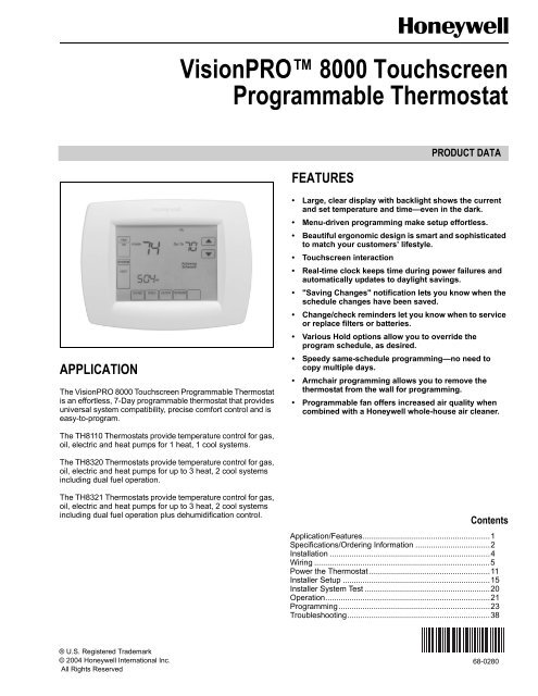
APPLICATION<br />
The VisionPRO <strong>8000</strong> <strong>Touchscreen</strong> <strong>Programmable</strong> <strong>Thermostat</strong><br />
is an effortless, 7-Day programmable thermostat that provides<br />
universal system compatibility, precise comfort control and is<br />
easy-to-program.<br />
The TH8110 <strong>Thermostat</strong>s provide temperature control for gas,<br />
oil, electric and heat pumps for 1 heat, 1 cool systems.<br />
The TH8320 <strong>Thermostat</strong>s provide temperature control for gas,<br />
oil, electric and heat pumps for up to 3 heat, 2 cool systems<br />
including dual fuel operation.<br />
The TH8321 <strong>Thermostat</strong>s provide temperature control for gas,<br />
oil, electric and heat pumps for up to 3 heat, 2 cool systems<br />
including dual fuel operation plus dehumidification control.<br />
® U.S. Registered Trademark<br />
© 2004 Honeywell International Inc.<br />
All Rights Reserved<br />
VisionPRO <strong>8000</strong> <strong>Touchscreen</strong><br />
<strong>Programmable</strong> <strong>Thermostat</strong><br />
FEATURES<br />
PRODUCT DATA<br />
• Large, clear display with backlight shows the current<br />
and set temperature and time—even in the dark.<br />
• Menu-driven programming make setup effortless.<br />
• Beautiful ergonomic design is smart and sophisticated<br />
to match your customers’ lifestyle.<br />
• <strong>Touchscreen</strong> interaction<br />
• Real-time clock keeps time during power failures and<br />
automatically updates to daylight savings.<br />
• "Saving Changes" notification lets you know when the<br />
schedule changes have been saved.<br />
• Change/check reminders let you know when to service<br />
or replace filters or batteries.<br />
• Various Hold options allow you to override the<br />
program schedule, as desired.<br />
• Speedy same-schedule programming—no need to<br />
copy multiple days.<br />
• Armchair programming allows you to remove the<br />
thermostat from the wall for programming.<br />
• <strong>Programmable</strong> fan offers increased air quality when<br />
combined with a Honeywell whole-house air cleaner.<br />
Contents<br />
Application/Features..........................................................1<br />
Specifications/Ordering Information ..................................2<br />
Installation .........................................................................4<br />
Wiring ................................................................................5<br />
Power the <strong>Thermostat</strong> .......................................................11<br />
Installer Setup ...................................................................15<br />
Installer System Test .........................................................20<br />
Operation...........................................................................21<br />
Programming.....................................................................23<br />
Troubleshooting.................................................................38<br />
68-0280
VisionPRO TM <strong>8000</strong> <strong>Touchscreen</strong> <strong>Programmable</strong> <strong>Thermostat</strong><br />
SPECIFICATIONS<br />
<strong>Thermostat</strong> Description:<br />
Feature Description<br />
Powering methods • Battery only<br />
• Common wire only<br />
• Common wire with battery backup<br />
System types (up to<br />
3 heat/2 cool or up<br />
to 1heat/1cool,<br />
depending on<br />
model)<br />
Electrical Ratings:<br />
Temperature Setting Range:<br />
Heating: 40°F to 90°F(4.5°C to 32°C).<br />
Cooling: 50°F to 99°F (10°C to 37°C).<br />
• Gas, oil or electric heat with air<br />
conditioning<br />
• Warm air, hot water, high-efficiency<br />
furnaces, heat pumps, steam and<br />
gravity<br />
• Heat only—includes power to open<br />
and power to close zone valves<br />
(series 20) and normally-open zone<br />
valves<br />
• Heat only with fan<br />
• Cool only<br />
• 750 mV heating systems<br />
Changeover Manual or Auto changeover selectable<br />
System setting Heat-Off-Cool-Auto (Em. Heat for heat<br />
pumps)<br />
Fan setting Auto-On-Circ<br />
Terminal Voltage (50/60 Hz) Running Current<br />
W Heating 20 - 30 Vac .02 - 1.0A<br />
W Heating<br />
(Powerpile)<br />
750 mV dc 100 mA dc<br />
Y Cooling 20 - 30 Vac .02 - 1.0A<br />
G Fan 20 - 30 Vac .02 - .60A<br />
Operating Ambient Temperature:<br />
TH<strong>8000</strong> VisionPRO <strong>Thermostat</strong>s: 0°F to 120°F<br />
(-18°C to 49°C).<br />
C7089U: -40°F to 120°F (-40°C to 49°C).<br />
C7189U: 45°F to 88°F (7.2°C to 32°C).<br />
ORDERING INFORMATION<br />
When purchasing replacement and modernization products from your TRADELINE® wholesaler or distributor, refer to the<br />
TRADELINE® Catalog or price sheets for complete ordering number.<br />
If you have additional questions, need further information, or would like to comment on our products or services, please write or<br />
phone:<br />
1. Your local Honeywell Automation and Control Products Sales Office (check white pages of your phone directory).<br />
2. Honeywell Customer Care<br />
1885 Douglas Drive North<br />
Minneapolis, Minnesota 55422-4386<br />
In Canada—Honeywell Limited/Honeywell Limitée, 35 Dynamic Drive, Scarborough, Ontario M1V 4Z9.<br />
International Sales and Service Offices in all principal cities of the world. Manufacturing in Australia, Canada, Finland, France,<br />
Germany, Japan, Mexico, Netherlands, Spain, Taiwan, United Kingdom, U.S.A.<br />
68-0280 2<br />
Shipping Temperature:<br />
TH<strong>8000</strong> VisionPRO <strong>Thermostat</strong>s: -30 °F to 150 °F<br />
(-34.4°C to 65.6°C).<br />
Operating Relative Humidity (Non-condensing):<br />
TH<strong>8000</strong> VisionPRO <strong>Thermostat</strong>s: 5% to 90%.<br />
C7089U: 5% to 95%.<br />
C7189U: 5% to 95%.<br />
Humidity Setting Range (TH8321 models only):<br />
Cooling: 40% to 80% RH.<br />
Humidity Display Range (TH8321 models only):<br />
0% to 99%.<br />
Cycle Rates (at 50% Load):<br />
Heating: Selectable 1 - 12 cycles per hour.<br />
Cooling: Selectable 1 - 6 cycles per hour.<br />
Finish:<br />
TH<strong>8000</strong> VisionPRO <strong>Thermostat</strong>s: Premier White® color.<br />
C7189U Wall Mount Remote Indoor Sensor: Premier White®<br />
color.<br />
Clock Accuracy: +/- 1 minute per month.<br />
Batteries:<br />
Three replaceable AAA alkaline batteries: Power thermostats<br />
when 24 Vac common is not used. Non-replaceable<br />
lithium battery with ten-year life under normal use to hold<br />
calendar and time settings. Alkaline batteries keep calendar<br />
and time after lithium battery is no longer functional.<br />
Resistance Characteristics of Remote Sensors:<br />
C7089U Outdoor Sensor: Negative temperature coefficient<br />
(NTC) means that resistance decreases as the<br />
temperature increases. See Table 13 in the Operation<br />
section for sensor resistance characteristics.<br />
C7189U Remote Indoor Sensor: Negative temperature<br />
coefficient (NTC), means that resistance decreases as the<br />
temperature increases. See Table 14 in the Operation<br />
section for sensor resistance characteristics.<br />
Cool Indication:<br />
TH<strong>8000</strong> VisionPRO <strong>Touchscreen</strong> <strong>Thermostat</strong>s show "Cool<br />
On" on the screen when Cool is activated.<br />
Heat Indication:<br />
TH<strong>8000</strong> VisionPRO <strong>Touchscreen</strong> <strong>Thermostat</strong>s show “Heat<br />
On” on the screen when Heat is activated.
Auxiliary Heat Indication:<br />
TH<strong>8000</strong> VisionPRO <strong>Touchscreen</strong> <strong>Thermostat</strong>s show “Aux.<br />
Heat On” on the screen when Auxiliary Heat is activated.<br />
Emergency Heat Indication:<br />
TH<strong>8000</strong> VisionPRO <strong>Touchscreen</strong> <strong>Thermostat</strong>s show “Heat<br />
On” on the screen when Emergency Heat is activated and<br />
the System mode is in the Em. Heat position.<br />
Calibration:<br />
C7089U, C7189U and TH<strong>8000</strong> VisionPRO <strong>Touchscreen</strong><br />
<strong>Thermostat</strong>s are factory-calibrated and require no field<br />
calibration.<br />
Interstage Differential:<br />
TH<strong>8000</strong> VisionPRO <strong>Touchscreen</strong> <strong>Thermostat</strong>s operate with<br />
droopless control. Once the thermostat senses that<br />
1st stage is running at 90% capacity, the thermostat<br />
energizes 2nd stage.<br />
Nomenclature:<br />
Series<br />
VisionPRO<br />
<strong>8000</strong><br />
<strong>Touchscreen</strong><br />
System<br />
Stages Application<br />
11 - 1H/1C<br />
32 - 3H/2C<br />
0 - Standard<br />
1 - Humidity<br />
Sensor<br />
Mounting Means:<br />
TH<strong>8000</strong> VisionPRO <strong>Touchscreen</strong> <strong>Thermostat</strong>: Mounts<br />
directly on the wall in the living space using mounting<br />
screws and anchors provided. Fits a vertical or horizontal<br />
2 x 4 in. junction box.<br />
C7089U Outdoor Sensor: Mounts outside of living space with<br />
mounting clip and screws provided.<br />
C7189U Remote Indoor Sensor: Mounts directly on the wall<br />
using mounting screws and anchors provided. Fits a<br />
vertical 2 x 4 in. junction box.<br />
Cover Plate:<br />
32003796-001 Cover Plate is used to cover marks left on the<br />
wall by the old thermostat.<br />
Dimensions:<br />
TH<strong>8000</strong> <strong>Touchscreen</strong> <strong>Thermostat</strong>: see Fig. 1.<br />
C7089U Outdoor Sensor Mounting Clip: see Fig. 2.<br />
32003796-001 Cover Plate: see Fig. 3.<br />
C7189U Remote Indoor Sensor: see Fig. 4.<br />
Power and System<br />
Changeover<br />
U - Universal (Auto<br />
changeover and/or<br />
manual changeover)<br />
dual powered,<br />
system flexibility,<br />
schedule flexibility.<br />
VisionPRO TM <strong>8000</strong> <strong>Touchscreen</strong> <strong>Programmable</strong> <strong>Thermostat</strong><br />
Fig. 1. TH<strong>8000</strong> <strong>Touchscreen</strong> <strong>Thermostat</strong><br />
dimensions in in. (mm).<br />
Fig. 2. C7089U Outdoor Sensor Mounting Clip<br />
dimensions in in. (mm).<br />
5-1/2<br />
(140)<br />
3-5/16<br />
(84)<br />
WALLPLATE<br />
3-3/8 (86)<br />
THERMOSTAT<br />
6 (152)<br />
1-1/2 (38)<br />
7-7/8 (200)<br />
3-5/16 (84)<br />
M4488<br />
3-3/8 (86)<br />
4-9/16<br />
(116)<br />
THERMOSTAT<br />
AND WALLPLATE<br />
1-3/8 (35)<br />
M22421<br />
M22139<br />
Fig. 3. 32003796-001 Cover Plate dimensions in in. (mm).<br />
3 68-0280
VisionPRO TM <strong>8000</strong> <strong>Touchscreen</strong> <strong>Programmable</strong> <strong>Thermostat</strong><br />
INSTALLATION<br />
68-0280 4<br />
Fig. 4. C7189U Remote Indoor Sensor dimensions in in. (mm).<br />
When Installing this Product...<br />
1. Read these instructions carefully. Failure to follow the<br />
instructions can damage the product or cause a hazardous<br />
condition.<br />
2. Check the ratings given in the instructions to make sure<br />
the product is suitable for your application.<br />
3. Installer must be a trained, experienced service<br />
technician.<br />
4. After completing installation, use these instructions to<br />
check out the product operation.<br />
Selecting Location<br />
Install the thermostat about 5 ft. (1.5m) above the floor in an<br />
area with good air circulation at average temperature. See<br />
Fig. 5.<br />
NO<br />
4-5/8<br />
(117)<br />
NO<br />
M4465<br />
YES<br />
5 FEET<br />
[1.5 METERS]<br />
Fig. 5. Selecting thermostat location.<br />
4-5/8<br />
(117)<br />
1-1/8<br />
2-3/4 (70) 2-3/4 (70)<br />
(29)<br />
FRONT VIEW SIDE VIEW FRONT VIEW (COVER OFF)<br />
NO<br />
M19925<br />
Do not install the thermostat where it can be affected by:<br />
— Drafts or dead spots behind doors and in corners.<br />
— Hot or cold air from ducts.<br />
— Radiant heat from sun or appliances.<br />
— Concealed pipes and chimneys.<br />
— Unheated (uncooled) areas such as an outside wall behind<br />
the thermostat.<br />
Installing Wallplate<br />
3-1/4<br />
(83)<br />
CAUTION<br />
Electrical Hazard.<br />
Can cause electrical shock or equipment damage.<br />
Disconnect power before wiring.<br />
The thermostat can be mounted horizontally on the wall or on<br />
a 4 in. x 2 in. (101.6 mm x 50.8 mm) wiring box.<br />
1. Position and level the wallplate (for appearance only).<br />
2. Use a pencil to mark the mounting holes.<br />
3. Remove the wallplate from the wall and, if drywall, drill<br />
two 3/16-in. holes in the wall, as marked. For firmer<br />
material such as plaster, drill two 7/32-in. holes. Gently<br />
tap anchors (provided) into the drilled holes until flush<br />
with the wall.
4. Position the wallplate over the holes, pulling wires<br />
through the wiring opening. See Fig. 6.<br />
5. Insert the mounting screws into the holes and tighten.<br />
MOUNTING<br />
HOLES<br />
MOUNTING<br />
SCREWS (2)<br />
WALL<br />
WIRES THROUGH WALL<br />
AND WIRE SLOT<br />
Fig. 6. Mounting wallplate.<br />
WIRING (FIG. 9 - 21)<br />
WALL ANCHORS (2)<br />
M19916<br />
All wiring must comply with local electrical codes and<br />
ordinances.<br />
1. Select set of terminal identifications (Table 1) that<br />
corresponds with system type (conventional or heat<br />
pump in Fig. 7).<br />
2. Loosen the screws for the appropriate system type<br />
selected; see Table 1. See Table 2 for terminal<br />
designation descriptions. Insert wires in the terminal<br />
block under the loosened screw. See Fig. 8.<br />
3. Securely tighten each screw.<br />
4. Push excess wire back into the hole.<br />
5. Plug the hole with nonflammable insulation to prevent<br />
drafts from affecting the thermostat.<br />
6. See Fig. 9 through 21 for typical wiring hookups.<br />
Y2<br />
L<br />
E<br />
AUX<br />
S1<br />
S2<br />
Y2<br />
W2<br />
S1<br />
S2<br />
HEAT PUMP<br />
CONVENTIONAL<br />
RC<br />
R<br />
W<br />
Y<br />
G<br />
C<br />
SCREW TERMINALS<br />
RC<br />
R<br />
O/B<br />
Y<br />
G<br />
C<br />
M19951<br />
Fig. 7. Selecting terminal identifications for<br />
system type.<br />
VisionPRO TM <strong>8000</strong> <strong>Touchscreen</strong> <strong>Programmable</strong> <strong>Thermostat</strong><br />
Table 1. Selecting Terminal Identifications for<br />
System Type.<br />
System Type<br />
Wallplate<br />
Terminal<br />
Identifications<br />
Fig. 8. Inserting wires in terminal block.<br />
IMPORTANT<br />
Use 18 gauge thermostat wire.<br />
Wiring<br />
Diagram<br />
Reference<br />
Standard Heat/Cool Conventional 9, 10<br />
Heat Only Conventional 11<br />
Heat Only with Fan Conventional 12<br />
Heat Only (Series 20)<br />
Power to open and<br />
power to close zone<br />
valves<br />
Normally Open Zone<br />
Valves—Heat Only<br />
Conventional 13<br />
Conventional 14<br />
Cool Only Conventional 15<br />
Standard Multistage up<br />
to 2 Heat/2 Cool<br />
Heat Pump with No<br />
Auxiliary Heat<br />
Heat Pump with<br />
Auxiliary Heat<br />
Conventional 16, 17<br />
Heat Pump 18, 19<br />
Heat Pump 20, 21<br />
M19917<br />
5 68-0280
VisionPRO TM <strong>8000</strong> <strong>Touchscreen</strong> <strong>Programmable</strong> <strong>Thermostat</strong><br />
Table 2. Terminal Designation Descriptions.<br />
Terminal<br />
Designation Description<br />
Rc (see Note<br />
1)<br />
Power for cooling--connect to<br />
secondary side of cooling system<br />
transformer<br />
R (see Note 1) Power for heating--connect to<br />
secondary side of heating system<br />
transformer<br />
C (see Note 2) Common wire from secondary side of<br />
cooling system transformer<br />
W Heat relay<br />
Y Compressor contactor<br />
G Fan relay<br />
Y2 Second stage cooling<br />
W2 Second stage heat relay<br />
O/B (see Note<br />
3)<br />
Changeover valve for heat pump<br />
systems<br />
AUX Auxiliary heat relay for heat pump<br />
systems<br />
E Emergency heat relay for heat pump<br />
systems<br />
L (see note 4) Equipment monitor for heat pump<br />
systems<br />
S1, S2 Optional outdoor or indoor remote<br />
sensor<br />
NOTES:<br />
1. When used in a single-transformer system, leave<br />
metal jumper wire in place between Rc and R. If<br />
used on a two-transformer system, remove metal<br />
jumper wire between Rc and R.<br />
2. Common wire is optional when thermostat is used<br />
with batteries.<br />
3. If thermostat is configured for a heat pump system<br />
in the Installer Setup, configure changeover valve<br />
for cool (O-factory setting) or heat (B).<br />
4. L terminal is an input (system monitor) when the<br />
System mode is in the Heat, Off, Cool or Auto<br />
position. L terminal is a 24 Vac output when<br />
System mode is Emergency Heat. Must connect<br />
the 24 Vac Common when using the L terminal.<br />
See LED Indication section for more details.<br />
68-0280 6<br />
OUTDOOR/INDOOR<br />
TEMPERATURE<br />
SENSOR<br />
1<br />
2<br />
3<br />
Y2 RC<br />
R<br />
W<br />
W2 Y<br />
S1 G<br />
S2 C<br />
FAN<br />
RELAY<br />
COMPRESSOR<br />
CONTACTOR<br />
HEAT RELAY<br />
POWER SUPPLY. PROVIDE DISCONNECT MEANS AND OVERLOAD<br />
PROTECTION AS REQUIRED.<br />
FACTORY INSTALLED JUMPER.<br />
CONVENTIONAL<br />
2<br />
OPTIONAL<br />
24 VAC<br />
COMMON<br />
CONNECTION<br />
3 OPTIONAL OUTDOOR OR INDOOR REMOTE SENSOR. AVAILABLE<br />
ON SELECT MODELS. WIRES MUST HAVE A CABLE SEPARATE<br />
FROM THE THERMOSTAT CABLE.<br />
M19895<br />
Fig. 9. Typical hookup of conventional single-stage heat<br />
and cool system with single transformer<br />
(1H/1C conventional).<br />
3<br />
OUTDOOR/INDOOR<br />
TEMPERATURE<br />
SENSOR<br />
1<br />
2<br />
Y2 RC<br />
R<br />
W<br />
W2 Y<br />
S1 G<br />
S2 C<br />
CONVENTIONAL<br />
OPTIONAL<br />
24 VAC<br />
COMMON<br />
CONNECTION<br />
FAN<br />
RELAY<br />
COMPRESSOR<br />
CONTACTOR<br />
HEAT RELAY<br />
POWER SUPPLY. PROVIDE DISCONNECT MEANS AND OVERLOAD<br />
PROTECTION AS REQUIRED.<br />
REMOVE FACTORY INSTALLED JUMPER.<br />
2<br />
Fig. 10. Typical hookup of conventional single-stage heat<br />
and cool system with two transformers<br />
(1H/1C conventional).<br />
1<br />
R<br />
C<br />
1<br />
R<br />
C<br />
1<br />
C<br />
R<br />
3 OPTIONAL OUTDOOR OR INDOOR REMOTE SENSOR. AVAILABLE<br />
ON SELECT MODELS. WIRES MUST HAVE A CABLE SEPARATE<br />
FROM THE THERMOSTAT CABLE.<br />
M19896
OUTDOOR/INDOOR<br />
TEMPERATURE<br />
SENSOR<br />
1<br />
2<br />
3<br />
3<br />
Y2 RC<br />
R<br />
W<br />
W2 Y<br />
S1 G<br />
S2 C<br />
HEAT RELAY<br />
POWER SUPPLY. PROVIDE DISCONNECT MEANS AND OVERLOAD<br />
PROTECTION AS REQUIRED.<br />
FACTORY INSTALLED JUMPER.<br />
CONVENTIONAL<br />
2<br />
OPTIONAL<br />
24 VAC<br />
COMMON<br />
CONNECTION<br />
OPTIONAL OUTDOOR OR INDOOR REMOTE SENSOR. AVAILABLE<br />
ON SELECT MODELS. WIRES MUST HAVE A CABLE SEPARATE<br />
FROM THE THERMOSTAT CABLE.<br />
M19897<br />
Fig. 11. Typical hookup of heat-only system<br />
(1 H conventional).<br />
3<br />
FAN<br />
RELAY<br />
OUTDOOR/INDOOR<br />
TEMPERATURE<br />
SENSOR HEAT RELAY<br />
1<br />
2<br />
Y2 RC<br />
R<br />
W<br />
W2 Y<br />
S1 G<br />
S2 C<br />
POWER SUPPLY. PROVIDE DISCONNECT MEANS AND OVERLOAD<br />
PROTECTION AS REQUIRED.<br />
FACTORY INSTALLED JUMPER.<br />
CONVENTIONAL<br />
2<br />
OPTIONAL<br />
24 VAC<br />
COMMON<br />
CONNECTION<br />
Fig. 12. Typical hookup of heat only system with fan<br />
(1H conventional).<br />
1<br />
R<br />
C<br />
1<br />
R<br />
3 OPTIONAL OUTDOOR OR INDOOR REMOTE SENSOR. AVAILABLE<br />
ON SELECT MODELS. WIRES MUST HAVE A CABLE SEPARATE<br />
FROM THE THERMOSTAT CABLE.<br />
M19898<br />
C<br />
VisionPRO TM <strong>8000</strong> <strong>Touchscreen</strong> <strong>Programmable</strong> <strong>Thermostat</strong><br />
OUTDOOR/INDOOR<br />
TEMPERATURE<br />
SENSOR<br />
1<br />
2<br />
3<br />
3<br />
Y2 RC<br />
R<br />
W<br />
W2 Y<br />
S1 G<br />
S2 C<br />
POWER SUPPLY. PROVIDE DISCONNECT MEANS AND OVERLOAD<br />
PROTECTION AS REQUIRED.<br />
FACTORY INSTALLED JUMPER.<br />
CONVENTIONAL<br />
OPTIONAL OUTDOOR OR INDOOR REMOTE SENSOR. AVAILABLE<br />
ON SELECT MODELS. WIRES MUST HAVE A CABLE SEPARATE<br />
FROM THE THERMOSTAT CABLE.<br />
M19899<br />
Fig. 13. Typical hookup of heat only power to open and<br />
power to close zone valve (Series 20) system.<br />
OUTDOOR/INDOOR<br />
TEMPERATURE<br />
SENSOR<br />
1<br />
2<br />
3<br />
4<br />
3<br />
Y2 RC<br />
R<br />
W<br />
W2 Y<br />
S1 G<br />
S2 C<br />
4<br />
Fig. 14. Typical hookup of heat only system with normally<br />
open zone valves.<br />
7 68-0280<br />
2<br />
W B R<br />
TR<br />
TR<br />
SERIES 20<br />
MOTOR OR<br />
VALVE<br />
POWER SUPPLY. PROVIDE DISCONNECT MEANS AND OVERLOAD<br />
PROTECTION AS REQUIRED.<br />
FACTORY INSTALLED JUMPER.<br />
CONVENTIONAL<br />
2<br />
NORMALLY OPEN<br />
ZONE VALVE<br />
OPTIONAL<br />
24 VAC<br />
COMMON<br />
CONNECTION<br />
OPTIONAL OUTDOOR OR INDOOR REMOTE SENSOR. AVAILABLE<br />
ON SELECT MODELS. WIRES MUST HAVE A CABLE SEPARATE<br />
FROM THE THERMOSTAT CABLE.<br />
1<br />
R<br />
CONFIGURE SYSTEM TYPE TO HEAT ONLY WITH NORMALLY OPEN<br />
ZONE VALVES IN INSTALLER SETUP.<br />
M22422<br />
C<br />
1<br />
R<br />
C
VisionPRO TM <strong>8000</strong> <strong>Touchscreen</strong> <strong>Programmable</strong> <strong>Thermostat</strong><br />
OUTDOOR/INDOOR<br />
TEMPERATURE<br />
SENSOR<br />
1<br />
2<br />
3<br />
3<br />
Y2 RC<br />
R<br />
W<br />
W2 Y<br />
S1 G<br />
S2 C<br />
FAN<br />
RELAY<br />
POWER SUPPLY. PROVIDE DISCONNECT MEANS AND OVERLOAD<br />
PROTECTION AS REQUIRED.<br />
FACTORY INSTALLED JUMPER.<br />
CONVENTIONAL<br />
2<br />
COMPRESSOR<br />
CONTACTOR<br />
OPTIONAL<br />
24 VAC<br />
COMMON<br />
CONNECTION<br />
OPTIONAL OUTDOOR OR INDOOR REMOTE SENSOR. AVAILABLE<br />
ON SELECT MODELS. WIRES MUST HAVE A CABLE SEPARATE<br />
FROM THE THERMOSTAT CABLE.<br />
M19900<br />
Fig. 15. Typical hookup of cool only system<br />
(1C conventional).<br />
OUTDOOR/INDOOR<br />
TEMPERATURE<br />
SENSOR<br />
1<br />
2<br />
3<br />
3<br />
HEAT RELAY 2<br />
Y2 RC<br />
R<br />
W<br />
2<br />
W2 Y<br />
S1 G<br />
S2 C<br />
COOL RELAY 2<br />
FAN<br />
RELAY<br />
POWER SUPPLY. PROVIDE DISCONNECT MEANS AND OVERLOAD<br />
PROTECTION AS REQUIRED.<br />
FACTORY INSTALLED JUMPER.<br />
CONVENTIONAL<br />
HEAT RELAY 1<br />
OPTIONAL<br />
24 VAC<br />
COMMON<br />
CONNECTION<br />
MUST COME<br />
FROM THE<br />
COOLING<br />
TRANSFORMER.<br />
COOL RELAY 1<br />
Fig. 16. Typical hookup of conventional multistage<br />
two-stage heating and two-stage cooling in a<br />
single-transformer system<br />
(2H/2C, 2H/1C or 1H/2C conventional).<br />
68-0280 8<br />
1<br />
R<br />
OPTIONAL OUTDOOR OR INDOOR REMOTE SENSOR. AVAILABLE<br />
ON SELECT MODELS. WIRES MUST HAVE A CABLE SEPARATE<br />
FROM THE THERMOSTAT CABLE.<br />
M22438B<br />
C<br />
1<br />
R<br />
C<br />
OUTDOOR/INDOOR<br />
TEMPERATURE<br />
SENSOR<br />
1<br />
2<br />
3<br />
HEAT RELAY 2<br />
Y2 RC<br />
R<br />
W<br />
W2 Y<br />
S1 G<br />
S2 C<br />
FAN<br />
RELAY<br />
POWER SUPPLY. PROVIDE DISCONNECT MEANS AND OVERLOAD<br />
PROTECTION AS REQUIRED.<br />
FACTORY INSTALLED JUMPER.<br />
CONVENTIONAL<br />
2<br />
COOL RELAY 2<br />
HEAT RELAY 1<br />
OPTIONAL<br />
24 VAC<br />
COMMON<br />
CONNECTION<br />
MUST COME<br />
FROM THE<br />
COOLING<br />
TRANSFORMER.<br />
COOL RELAY 1<br />
Fig. 17. Typical hookup of conventional multistage<br />
two-stage heating and two-stage cooling in a<br />
two-transformer system (2H/2C, 2H/1C or<br />
1H/2C conventional).<br />
1<br />
R<br />
3 OPTIONAL OUTDOOR OR INDOOR REMOTE SENSOR. AVAILABLE<br />
ON SELECT MODELS. WIRES MUST HAVE A CABLE SEPARATE<br />
FROM THE THERMOSTAT CABLE.<br />
M19902B<br />
C<br />
1<br />
R<br />
C
4<br />
Y2<br />
L<br />
E<br />
SI<br />
OUTDOOR/INDOOR<br />
TEMPERATURE<br />
SENSOR<br />
HEAT PUMP<br />
VisionPRO TM <strong>8000</strong> <strong>Touchscreen</strong> <strong>Programmable</strong> <strong>Thermostat</strong><br />
Fig. 18. Typical hookup of single-stage heat pump with no auxiliary/backup heat (1H/1C heat pump).<br />
Fig. 19. Typical hookup of multistage heat pump with no auxiliary/backup heat (2H/2C heat pump).<br />
2<br />
RC<br />
R<br />
Y<br />
G<br />
C<br />
3<br />
CHANGEOVER<br />
VALVE<br />
OPTIONAL 24 VAC<br />
COMMON CONNECTION<br />
FAN RELAY<br />
COMPRESSOR<br />
RELAY<br />
1 POWER SUPPLY. PROVIDE DISCONNECT MEANS AND OVERLOAD PROTECTION AS REQUIRED.<br />
2 FACTORY INSTALLED JUMPER.<br />
3 "O/B" TERMINAL SET TO CONTROL AS EITHER "O" OR "B" IN THE INSTALLER SETUP.<br />
4 OPTIONAL OUTDOOR OR INDOOR REMOTE SENSOR. AVAILABLE ON SELECT MODELS. WIRES MUST HAVE A CABLE SEPARATE<br />
FROM THE THERMOSTAT CABLE.<br />
3<br />
5<br />
Y2<br />
L<br />
E<br />
SI<br />
OUTDOOR/INDOOR<br />
TEMPERATURE<br />
SENSOR<br />
HEAT PUMP<br />
COMPRESSOR 2<br />
2<br />
RC<br />
R<br />
Y<br />
G<br />
C<br />
CHANGEOVER<br />
VALVE<br />
FAN RELAY<br />
COMPRESSOR 1<br />
1 POWER SUPPLY. PROVIDE DISCONNECT MEANS AND OVERLOAD PROTECTION AS REQUIRED.<br />
2 FACTORY INSTALLED JUMPER.<br />
3 MUST CONNECT THE 24 VAC COMMON WHEN USING L. THE TERMINAL IS SHOWN AS EQUIPMENT MONITOR, CAN ALSO BE USED AS A 24 VAC<br />
OUTPUT. SEE "HEAT PUMP LED" SECTION FOR MORE INFORMATION.<br />
4 "O/B" TERMINAL SET TO CONTROL AS EITHER "O" OR "B" IN THE INSTALLER SETUP.<br />
5 OPTIONAL OUTDOOR OR INDOOR REMOTE SENSOR. AVAILABLE ON SELECT MODELS. WIRES MUST HAVE A CABLE SEPARATE FROM THE<br />
THERMOSTAT CABLE.<br />
M19904<br />
4<br />
OPTIONAL 24 VAC<br />
COMMON CONNECTION<br />
M19903B<br />
9 68-0280<br />
1<br />
R<br />
C<br />
1<br />
R<br />
C
VisionPRO TM <strong>8000</strong> <strong>Touchscreen</strong> <strong>Programmable</strong> <strong>Thermostat</strong><br />
Fig. 20. Typical hookup of single-stage heat pump with auxiliary/backup heat (2H/1C heat pump).<br />
Fig. 21. Typical hookup of multistage heat pump with auxiliary/backup heat (3H/2C heat pump).<br />
68-0280 10<br />
5<br />
Y2<br />
L<br />
E<br />
SI<br />
3<br />
OUTDOOR/INDOOR<br />
TEMPERATURE<br />
4<br />
SENSOR<br />
HEAT 2 RELAY<br />
(AUXILIARY HEAT)<br />
HEAT PUMP<br />
2<br />
EMERGENCY<br />
HEAT RELAY<br />
R<br />
Y<br />
G<br />
C<br />
CHANGEOVER<br />
VALVE<br />
FAN RELAY<br />
COMPRESSOR<br />
RELAY<br />
1 POWER SUPPLY. PROVIDE DISCONNECT MEANS AND OVERLOAD PROTECTION AS REQUIRED.<br />
2 FACTORY INSTALLED JUMPER.<br />
3 OUTDOOR SENSOR REQUIRED IN SYSTEM WITH FOSSIL FUEL BACKUP HEAT THAT IS NOT USING AN EXTERNAL FOSSIL FUEL KIT.<br />
4 OPTIONAL OUTDOOR OR INDOOR REMOTE SENSOR. AVAILABLE ON SELECT MODELS. WIRES MUST HAVE A CABLE SEPARATE<br />
FROM THE THERMOSTAT CABLE.<br />
5 MUST CONNECT THE 24 VAC COMMON WHEN USING L. THE TERMINAL IS SHOWN AS EQUIPMENT MONITOR, CAN ALSO BE USED AS<br />
A 24 VAC OUTPUT. SEE "HEAT PUMP LED" SECTION FOR MORE INFORMATION.<br />
6 "O/B" TERMINAL SET TO CONTROL AS EITHER "O" OR "B" IN THE INSTALLER SETUP.<br />
M19905<br />
5<br />
3<br />
4<br />
Y2<br />
L<br />
E<br />
SI<br />
HEAT 2 RELAY<br />
(AUXILIARY HEAT)<br />
OUTDOOR/INDOOR<br />
TEMPERATURE<br />
SENSOR<br />
EMERGENCY<br />
HEAT RELAY<br />
HEAT PUMP<br />
2<br />
R<br />
Y<br />
G<br />
C<br />
6<br />
CHANGEOVER<br />
VALVE<br />
EQUIPMENT<br />
MONITOR<br />
OPTIONAL 24 VAC<br />
COMMON CONNECTION<br />
FAN RELAY<br />
COMPRESSOR 2 COMPRESSOR 1<br />
1 POWER SUPPLY. PROVIDE DISCONNECT MEANS AND OVERLOAD PROTECTION AS REQUIRED.<br />
2 FACTORY INSTALLED JUMPER.<br />
3 OUTDOOR SENSOR REQUIRED IN SYSTEM WITH FOSSIL FUEL BACKUP HEAT THAT IS NOT USING AN EXTERNAL FOSSIL FUEL KIT.<br />
4 OPTIONAL OUTDOOR OR INDOOR REMOTE SENSOR. AVAILABLE ON SELECT MODELS. WIRES MUST HAVE A CABLE SEPARATE<br />
FROM THE THERMOSTAT CABLE.<br />
5 MUST CONNECT THE 24 VAC COMMON WHEN USING L. THE TERMINAL IS SHOWN AS EQUIPMENT MONITOR, CAN ALSO BE USED AS<br />
A 24 VAC OUTPUT. SEE "HEAT PUMP LED" SECTION FOR MORE INFORMATION.<br />
6 "O/B" TERMINAL SET TO CONTROL AS EITHER "O" OR "B" IN THE INSTALLER SETUP.<br />
M19906<br />
6<br />
EQUIPMENT<br />
MONITOR<br />
OPTIONAL 24 VAC<br />
COMMON CONNECTION<br />
1<br />
R<br />
C<br />
1<br />
R<br />
C
POWER THE THERMOSTAT<br />
You can choose from three methods to power the thermostat:<br />
• Batteries only (AAA alkaline).<br />
• 24 Vac common wire only.<br />
• 24 Vac common wire with battery backup (AAA alkaline).<br />
Wiring 24 Vac Common<br />
• Single-Transformer System—Connect the common side of<br />
the transformer to the C screw terminal of the thermostat<br />
wallplate. Leave the metal jumper wire in place between<br />
Rc and R.<br />
• Two-Transformer System—Connect the common side of<br />
the cooling transformer to the C screw terminal of the<br />
thermostat wallplate. Remove the metal jumper wire<br />
between Rc and R.<br />
Installing Batteries<br />
1. Install three AAA alkaline batteries on the back of the<br />
thermostat as marked on the thermostat. See<br />
Fig. 22.<br />
BATTERIES (3)<br />
Fig. 22. Installing batteries.<br />
M19918<br />
VisionPRO TM <strong>8000</strong> <strong>Touchscreen</strong> <strong>Programmable</strong> <strong>Thermostat</strong><br />
2. Locate and remove the tab labeled, Remove, in the<br />
lower left corner on the thermostat back. See<br />
Fig. 23.<br />
REMOVE<br />
TAB<br />
Fig. 23. Remove tab labeled, Remove, on<br />
thermostat back.<br />
Mount <strong>Thermostat</strong> to Wallplate<br />
1. Align the terminal screw blocks with the pins on the<br />
back of the thermostat. Push the thermostat straight<br />
onto the wallplate until it snaps into place. See Fig 24.<br />
TERMINAL<br />
SCREW<br />
BLOCK<br />
REMOVE DURING<br />
INSTALLATION<br />
WALLPLATE<br />
Fig. 24. Mount thermostat to wallplate.<br />
11 68-0280<br />
REMOVE DURING<br />
INSTALLATION<br />
M19920<br />
PINS ON<br />
BACK OF<br />
THERMOSTAT<br />
M22213
VisionPRO TM <strong>8000</strong> <strong>Touchscreen</strong> <strong>Programmable</strong> <strong>Thermostat</strong><br />
Locate and Mount C7089U Outdoor<br />
Temperature Sensor (Optional)<br />
Mount the sensor where (see Fig. 25):<br />
• cannot tamper with settings.<br />
• there is good air circulation.<br />
• it can measure true outdoor ambient temperature.<br />
• surface is flat.<br />
• wire distance between C7089 and thermostat is less than<br />
200 feet.<br />
Do not mount the sensor:<br />
• in direct sunlight.<br />
• where hot or cold air blows on the sensor. Discharge line<br />
from an outdoor compressor unit, vent or fan causes<br />
inaccurate temperature readings.<br />
• where snow, ice or debris can cover it.<br />
Use the following steps to mount the sensor:<br />
1. Remove the sensor from the mounting clip.<br />
2. Mark the area on the location selected for mounting the<br />
sensor mounting clip.<br />
3. Mount the clip.<br />
Fig. 25. Typical locations for C7089U Outdoor Sensor.<br />
Wire C7089U Outdoor Sensor<br />
CAUTION<br />
Electrical Interference (Noise) Hazard.<br />
Can cause erratic system operation.<br />
Keep wiring at least one foot away from large inductive<br />
loads such as motors, line starters, lighting ballasts<br />
and large power distribution panels.<br />
Use shielded cable to reduce interference when<br />
rerouting is not possible.<br />
68-0280 12<br />
M7514<br />
IMPORTANT<br />
Erratic temperature readings from a sensor can<br />
occur as a result of any of the wiring practices<br />
described below. Avoid these practices to assure<br />
correct operation. Use shielded cable to reduce<br />
interference if rerouting sensor wiring is not possible.<br />
— Be sure wires have a cable separate from the<br />
thermostat cable.<br />
— Do not route temperature sensor wiring with building<br />
power wiring, next to control contactors or near light<br />
dimming circuits, electric motors or welding<br />
equipment.<br />
— Avoid poor wiring connections.<br />
— Avoid intermittent or missing building earth ground.<br />
CAUTION<br />
Electrical Shock Hazard.<br />
Can cause electrical shock or equipment damage.<br />
Disconnect power supply before connecting wiring.<br />
Wiring must comply with applicable codes, ordinances and<br />
regulations:<br />
1. Wire C7089 Outdoor Sensor to S1and S2 terminals on<br />
the thermostat. If leadwire provided is not long enough<br />
(60 in.), run a cable to a hole at C7089 location.<br />
a. Using color-coded, 18-gauge thermostat wire is<br />
recommended. For example of general wiring of<br />
C7089, see Fig. 26.<br />
b. Pigtail wiring can be used.<br />
2. Mount C7089 in its mounting clip.<br />
3. Plug wiring hole using nonhardening caulk or putty.<br />
1<br />
2<br />
1<br />
C7089<br />
USE APPROPRIATE MOUNTING MEANS FOR THE<br />
TYPE OF STRUCTURE.<br />
PLUG WIRING HOLE WITH NON-HARDENING CAULK<br />
OR PUTTY.<br />
Fig. 26. Wire C7089 Outdoor Sensor to the thermostat.<br />
2<br />
WIRING HOLE<br />
THROUGH<br />
STRUCTURE<br />
M19970
Locate and Mount C7189U Remote Indoor<br />
Temperature Sensor (Optional)<br />
1. Choose a location (see Fig. 27) for mounting the sensor<br />
on an inside wall about 5 ft (1.5m) above the floor. A<br />
vertically-mounted standard 2 x 4 in. (51 x 102 mm)<br />
junction box can also be used.<br />
2. Be sure wire distance between C7189 and thermostat is<br />
less than 200 feet.<br />
3. Make sure there is good air circulation at average<br />
temperature at the chosen location. Avoid the following<br />
locations because they can introduce errors in sensor<br />
measurements. See Fig. 27.<br />
a. Hot areas caused by:<br />
(a) Concealed pipes or ducts.<br />
(b) Drafts from fireplaces or other heat sources.<br />
(c) Convection or radiant heat from the sun or<br />
electrical equipment.<br />
b. Cold areas caused by:<br />
(a) Concealed pipes or ducts.<br />
(b) Drafts from windows and doors.<br />
(c) Unheated areas on the other side of the wall<br />
location.<br />
c. Dead air areas:<br />
(a) Behind doors, furniture and curtains.<br />
(b) In corners and alcoves.<br />
4. Mark the area on the wall selected for mounting the<br />
C7189 Sensor or junction box.<br />
5. Run wire cable to a hole at the selected wall location.<br />
Pull approximately three inches of wire through the<br />
opening. Color-coded, 18-gauge thermostat wire is<br />
recommended.<br />
NO<br />
NO<br />
Fig. 27. Typical location for C7189 Indoor Sensor.<br />
YES<br />
5 FEET<br />
(1.5 METERS)<br />
NO<br />
M4476<br />
VisionPRO TM <strong>8000</strong> <strong>Touchscreen</strong> <strong>Programmable</strong> <strong>Thermostat</strong><br />
Wire C7189 Indoor Sensor<br />
CAUTION<br />
Electrical Interference (Noise) Hazard.<br />
Can cause erratic system operation.<br />
Keep wiring at least one foot away from large inductive<br />
loads such as motors, line starters, lighting ballasts<br />
and large power distribution panels.<br />
IMPORTANT<br />
Erratic temperature readings from a sensor can<br />
occur as a result of any of the wiring practices<br />
described below. Avoid these practices to assure<br />
correct operation.<br />
— Be sure wires have a cable separate from the<br />
thermostat cable.<br />
— Do not route temperature sensor wiring with building<br />
power wiring, next to control contactors or near light<br />
dimming circuits, electric motors or welding<br />
equipment.<br />
— Avoid poor wiring connections.<br />
— Avoid intermittent or missing building earth ground.<br />
CAUTION<br />
Electrical Shock Hazard.<br />
Can cause electrical shock or equipment damage.<br />
Disconnect power supply before connecting wiring.<br />
Wiring must comply with applicable codes, ordinances and<br />
regulations.<br />
1. Wire C7189 Indoor Sensor to S1and S2 terminals on<br />
the thermostat. For an example of general wiring of<br />
C7189, see Fig. 28 to wire one sensor and 29 to wire<br />
multiple sensors.<br />
2. Push excess wire back into the hole. Plug the hole<br />
using nonhardening caulk, putty or insulation to prevent<br />
drafts from affecting performance.<br />
3. Remove C7189 cover.<br />
4. Mount C7189 to the wall or junction box using the<br />
screws and anchors provided.<br />
5. Level the C7189 for appearance only. Device functions<br />
correctly even when not level.<br />
6. Install C7189 cover.<br />
13 68-0280
VisionPRO TM <strong>8000</strong> <strong>Touchscreen</strong> <strong>Programmable</strong> <strong>Thermostat</strong><br />
1<br />
2<br />
3<br />
Y2<br />
RC<br />
R<br />
C7189<br />
POWER SUPPLY. PROVIDE DISCONNECT MEANS AND<br />
OVERLOAD PROTECTION AS REQUIRED.<br />
Fig. 28. Wiring a single C7189 Indoor Sensor.<br />
Fig. 29. Wiring Multiple C7189 Sensors.<br />
68-0280 14<br />
2<br />
1<br />
R<br />
C<br />
IF MORE THAN ONE C7189 REMOTE SENSOR IS REQUIRED,<br />
REFER TO FIGURE 3.<br />
WIRES MUST HAVE A CABLE SEPARATE FROM THE<br />
THERMOSTAT CABLE.<br />
1<br />
2<br />
Y2<br />
W2<br />
1<br />
S2<br />
Y2<br />
W2<br />
1<br />
2<br />
2<br />
2<br />
SENSORS MUST BE ARRANGED IN THIS<br />
CONFIGURATION TO OPERATE CORRECTLY.<br />
3<br />
WIRES MUST HAVE A CABLE SEPARATE FROM THE<br />
THERMOSTAT CABLE.<br />
1<br />
C7189 C7189<br />
C7189 C7189<br />
1<br />
C7189 C7189<br />
C7189 C7189<br />
C7189<br />
C7189 C7189 C7189<br />
C7189<br />
M19972<br />
M19973<br />
Set Calendar and Time<br />
<strong>Thermostat</strong> keeps current time and day for up to ten years<br />
under normal use after the calendar is set.<br />
When the thermostat is first powered, the display is ready to<br />
set the calendar and time.<br />
NOTE: Calendar can also be set in the Installer Setup.<br />
1. Press the arrow keys to set the year, month and day.<br />
2. Press the Done key.<br />
SET CURRENT DAY<br />
SET MONTH<br />
MO TUE WE E TH FRR SA SU<br />
DONE<br />
USE ARROWS TO SET YEAR AND TIME<br />
3. Press the arrow keys to set the current time.<br />
4. Press the Done Key.<br />
MO WE W<br />
TH FR SA SU<br />
DONE<br />
M22424<br />
USE ARROWS TO SET YEAR AND TIME<br />
M22425
INSTALLER SETUP<br />
Follow these steps to enter the Installer Setup:<br />
1. Press and release the System Key.<br />
FAN<br />
ON<br />
AUTO<br />
Inside Set To<br />
SYSTEM<br />
EM HEAT<br />
OFF<br />
COOL<br />
A<br />
M<br />
THU<br />
SCHED HOLD CLOCK SCREE<br />
Following<br />
Schedule<br />
2. Press and hold the two blank keys on either side of the<br />
center blank key for approximately five seconds until<br />
screen changes.<br />
MON TUE WED THU FRI SAT AT SUN<br />
SYSTEM<br />
EM HEAT<br />
OFF<br />
COOL<br />
Inside Set To<br />
PM<br />
Following<br />
Schedule<br />
DONE CANCEL<br />
M22426A<br />
M19923<br />
VisionPRO TM <strong>8000</strong> <strong>Touchscreen</strong> <strong>Programmable</strong> <strong>Thermostat</strong><br />
3. Release the two blank keys when the screen on the<br />
thermostat matches the screen below.<br />
DONE<br />
M22442<br />
4. See screen below to review how the thermostat keys<br />
are used during Installer Setup. See Tables 3-5 for the<br />
Installer Setup Numbers and Settings.<br />
INSTALLER<br />
SETUP<br />
NUMBER<br />
MON WED THUU FRI SAT AT A SUN<br />
DONE O<br />
PRESS TO EXIT<br />
INSTALLER SETUP<br />
ADVANCE TO NEXT<br />
INSTALLER SETUP<br />
CURRENT<br />
SETTING<br />
CHANGE THE<br />
CURRENT<br />
SETTING M22443<br />
5. Press the Done key to exit the Installer Setup screen.<br />
15 68-0280
VisionPRO TM <strong>8000</strong> <strong>Touchscreen</strong> <strong>Programmable</strong> <strong>Thermostat</strong><br />
Table 3. Installer Setup Menu.<br />
Installer Setup<br />
Number Installer Setup Name Settings Notes<br />
0120 Date (Year Upper) Select first two digits of current calendar year (2005, etc) 2001 - 2178 available<br />
0130 Date (Year Lower) Select last two digits of current calendar year (05 for year 2001 - 2178 available<br />
2005, etc)<br />
0140 Date (Month) Select number that represents current calendar month —<br />
0150 Date (Day) Select number that represents current calendar date —<br />
0160 Schedule Options 0—nonprogrammable<br />
4—7-day programmable<br />
—<br />
0170 System Type Selection 1—1 heat/1 cool conventional (factory setting)<br />
Available options and<br />
2—single-stage heat pump (no auxiliary heat)<br />
defaults vary by<br />
3—heat only conventional (no fan) Also for 750mV. thermostat. System<br />
4—heat only conventional (with fan)<br />
selection automatically<br />
5—heat only (power to open and power to close zone modifies some default<br />
valves or normally-open zone valves)<br />
settings and/or hides<br />
6—cool only conventional<br />
other Installer Setup<br />
7—2 heat/1 cool heat pump (with auxiliary heat)<br />
8—2 heat/2 cool multistage conventional<br />
9—2 heat/1 cool multistage conventional<br />
10—1 heat/2 cool multistage conventional<br />
11—2 heat/2cool heat pump (no auxiliary heat)<br />
12—3 heat/2cool heat pump (with auxiliary heat)<br />
options.<br />
0180 Fan Control in Heating 0—gas or oil furnace equipment controls fan in heating Only shown if<br />
(factory setting)<br />
conventional system is<br />
1—electric furnace—thermostat controls fan in heating selected. If heat pump is<br />
chosen, fan defaults to<br />
electric.<br />
0190 Changeover Valve—O/B 0—changeover valve—O/B terminal is energized in Only shown if heat pump<br />
Terminal Energized in cooling (factory setting)<br />
system is chosen.<br />
Heating or Cooling 1—changeover valve—O/B terminal is energized in<br />
(Heat Pumps Only) heating<br />
0200 Backup Heat Source 0—heat pump backup heat source is electric (factory Only shown if 2 heat/<br />
(Auxiliary Heat) setting)<br />
1 cool or 3 heat/2 cool<br />
1—heat pump backup heat source is fossil fuel<br />
heat pump is chosen<br />
0210 External Fuel Fossil 0—no external fossil fuel kit is controlling heat pump Only shown if fossil fuel is<br />
Fuel Kit<br />
backup heat. This thermostat controls the dual fuel. Must chosen as backup heat<br />
install outdoor sensor and set Installer Setup Number<br />
0340 to number 2.<br />
1—external fossil fuel kit is controlling heat pump backup<br />
heat<br />
source.<br />
0220 Cycles per hour (cph) for 3—cph recommended for compressors (factory setting) —<br />
1st Stage Compressor 1, 2, 4, 5, 6—other cycle rate settings<br />
0230 Cycles per hour (cph) for 3—cph recommended for compressors (factory setting) Only shown if two stages<br />
2nd Stage Compressor 1, 2, 4, 5, 6—other cycle rate settings<br />
of cool are selected.<br />
0240 Cycles per hour (cph) for 1— 1 cph used for steam and gravity<br />
Not shown if system<br />
1st Stage Conventional 3—3 cph used for hot water system and high efficiency selection is heat pump.<br />
Heat<br />
(90% or better) furnaces<br />
5—5 cph used for standard fossil fuel forced air (less than Selection in this stage<br />
80% efficient) systems (factory setting)<br />
changes default cph for<br />
9—9 cph used for electric furnaces<br />
2, 4, 6, 7, 8, 10, 11, 12—other cycle rate settings<br />
2nd stage heat.<br />
0250 Cycles per hour (cph) for 1—1 cph used for steam and gravity<br />
Only shown if two stages<br />
2nd Stage Heat (Aux 3—3 cph for hot water systems and high efficiency (90% of heat are selected.<br />
Heat for 2H/1C Heat or better) furnaces<br />
Pumps)<br />
5—5 cph for standard fossil fuel forced air (less than 90%<br />
efficient) systems (factory setting)<br />
9—9 cph used for electric furnaces or electric auxiliary<br />
heat for heat pump systems<br />
2, 4, 6, 7, 8, 10, 11, 12—other cycle rate settings<br />
68-0280 16
0260 Cycles per hour (cph) for<br />
3rd Stage Heat<br />
(Aux Heat for 3H/2C<br />
Heat Pumps)<br />
0270 Cycles per hour (cph) for<br />
Em Heat<br />
VisionPRO TM <strong>8000</strong> <strong>Touchscreen</strong> <strong>Programmable</strong> <strong>Thermostat</strong><br />
1—1 cph used for steam and gravity<br />
3—3 cph for hot water systems and high efficiency (90%<br />
or better) furnaces<br />
5—5 cph for standard fossil fuel forced air (less than 90%<br />
efficient) systems (factory setting)<br />
9—9 cph used for electric furnaces or electric auxiliary<br />
heat for heat pump systems<br />
2, 4, 6, 7, 8, 10, 11, 12—other cycle rate settings<br />
3—3 cph for hot water systems and high efficiency (90%<br />
or better) furnaces<br />
5—5 cph for standard fossil fuel forced air (less than 90%<br />
efficient or better) systems<br />
9—9 cph for electric strip heat for heat pumps<br />
0280 Continuous Backlight 0—Backlight not on continuously. <strong>Thermostat</strong> backlight<br />
comes on with each key press.<br />
1—Backlight is on continuously (thermostat must have a<br />
common wire attached for this function).<br />
0300 Changeover 0—manual changeover (factory setting)<br />
1—auto changeover<br />
0310 Deadband Heating and cooling setpoints can be set no closer than<br />
chosen value:<br />
2—2 ° F (1.5 ° C)<br />
3—3 ° F (2 ° C)<br />
4—4 ° F (2.5 ° C)<br />
5—5 ° F (3 ° C)<br />
6—6 ° F (3.5 ° C)<br />
7—7 ° F (4 ° C)<br />
8—8 ° F (4.5 ° C)<br />
9—9 ° F (5 ° C)<br />
0320 Temperature Indication<br />
Scale<br />
0—fahrenheit temperature display (factory setting)<br />
1—celsius temperature display<br />
0330 Daylight Savings 1—daylight savings is on (factory setting).<br />
0—daylight savings is off.<br />
0340 Remote Temperature<br />
Sensor (Outdoor or<br />
Indoor)<br />
0350 Heat Pump Compressor<br />
Lockout or (Balance<br />
Point)<br />
Table 3. Installer Setup Menu. (Continued)<br />
Installer Setup<br />
Number Installer Setup Name Settings Notes<br />
0—no remote temperature sensor<br />
1—outdoor temperature sensor for display only.<br />
2—outdoor temperature sensor for control. Outdoor<br />
sensor used for Heat Pump Lockout settings. (See Heat<br />
Pump Temperature Lockout section for more details.)<br />
3—indoor temperature sensor<br />
0—no compressor lockout.<br />
15 ° F (-9.5 ° C)<br />
20 ° F (-6.5 ° C)<br />
25 ° F (-4 ° C)<br />
30 ° F (-1 ° C)<br />
35 ° F (1.5 ° C)<br />
40 ° F (4.5 ° C)<br />
45 ° F (7 ° C)<br />
Only shown if 3H/2C<br />
heat pump is selected.<br />
Only shown if 2H/1C or<br />
3H/2C heat pump is<br />
selected.<br />
Option is always shown;<br />
however, continuously on<br />
backlight works only if<br />
thermostat is wired with<br />
24 Vac Common.<br />
—<br />
Shown only if automatic<br />
changeover is selected.<br />
17 68-0280<br />
—<br />
Set to 0 in areas that do<br />
not follow daylight<br />
savings.<br />
Defaults and Options<br />
depend on System Type<br />
selection.<br />
Indoor Temperature<br />
Sensor uses an averaging<br />
network and does not<br />
include on-board sensor.<br />
Default depends on other<br />
selections. Shown if<br />
Outdoor Temperature for<br />
control is selected. (See<br />
Advanced Features<br />
section for more<br />
information.)
VisionPRO TM <strong>8000</strong> <strong>Touchscreen</strong> <strong>Programmable</strong> <strong>Thermostat</strong><br />
0360 Heat Pump Auxiliary<br />
Lockout<br />
0380 Indoor Dehumidification<br />
Control<br />
0500 Furnace Change<br />
Reminder<br />
0510 Humidifier Pad<br />
Replacement Reminder<br />
0520 UV Lamp Replacement<br />
Reminder<br />
0530 Adaptive Intelligent<br />
Recovery<br />
0—no auxiliary heat lockout.<br />
40 ° F (4.5 ° C)<br />
45 ° F (7 ° C)<br />
50 ° F (10 ° C)<br />
55 ° F (13 ° C)<br />
60 ° F (15.5 ° C)<br />
68-0280 18<br />
0—No indoor dehumidification control.<br />
1—Dehumidification control activated.<br />
0—furnace filter reminder off<br />
1—10 run time days<br />
2—30 run time days<br />
3—60 run time days<br />
4—90 run time days<br />
5—120 run time days<br />
6—365 run time days<br />
0—humidifier pad replacement reminder off<br />
1—90 calendar days<br />
2—180 calendar days<br />
3—365 calendar days<br />
0—UV lamp replacement reminder off<br />
1—365 calendar days<br />
1—Adaptive Intelligent Recovery control is activated<br />
(system starts early so setpoint is reached by start of<br />
program period).<br />
0—Conventional Recovery (system starts recovery at<br />
programmed time)<br />
0540 Number of Periods 2—two periods available (Wake and Sleep)<br />
4—four periods available (Wake, Leave, Return and<br />
Sleep)<br />
0580 Minimum Compressor<br />
Off Time<br />
0600 Heat Temperature<br />
Range Stop<br />
0610 Cool Temperature<br />
Range Stop<br />
Table 3. Installer Setup Menu. (Continued)<br />
Installer Setup<br />
Number Installer Setup Name Settings Notes<br />
5—five-minute compressor off-time setting (factory<br />
setting)<br />
0, 2, 3, 4—other compressor off-time settings<br />
40-90—temperature range (1°F increments) of heating<br />
setpoint.<br />
50-99—temperature range (1°F increments) of cooling<br />
setpoint.<br />
0640 Clock Format 12—12 hour clock (factory setting)<br />
24—24 hour clock<br />
Shown if electric is<br />
chosen for backup heat<br />
source and outdoor<br />
temperature sensor for<br />
control is selected. (See<br />
Advanced Features<br />
section for more<br />
information.)<br />
Available on select<br />
models.<br />
If dehumidification control<br />
is activated and autochangeover<br />
is selected in<br />
Installer Setup Number<br />
0300, the deadband<br />
minimum is defaulted to<br />
5 ° F (3 ° C) in Number<br />
0310.<br />
Run time based on call for<br />
fan.<br />
—<br />
—<br />
—<br />
Not shown if nonprogrammable<br />
is<br />
selected. 2 or 4 applies to<br />
all days of the week.<br />
—<br />
Shown in 1/2 °C.<br />
Shown in 1/2 °C.<br />
—
0650 Extended Fan OnTime<br />
Heat<br />
0660 Extended Fan On Time<br />
Cool<br />
0670 Keypad Lockout 0—unlocked keypad<br />
1—partially locked keypad<br />
2—fully locked keypad<br />
0680 Temperature Control in<br />
Heat<br />
0690 Temperature Control in<br />
Cool<br />
0700 Temperature Display<br />
Offset<br />
Table 3. Installer Setup Menu. (Continued)<br />
VisionPRO TM <strong>8000</strong> <strong>Touchscreen</strong> <strong>Programmable</strong> <strong>Thermostat</strong><br />
Installer Setup<br />
Number Installer Setup Name Settings Notes<br />
0—no extended fan operation after call for heat ends<br />
90— fan operation is extended 90 seconds after call for<br />
heat ends.<br />
0—no extended fan operation after call for cool ends<br />
90—fan operation is extended 90 seconds after call for<br />
cool ends.<br />
1—less aggressive temperature control (could cause<br />
temperature undershoot)<br />
2—Standard temperature control in heating (factory<br />
setting)<br />
3—more aggressive temperature control (could cause<br />
temperature overshoot)<br />
1—less aggressive temperature control (could cause<br />
temperature undershoot)<br />
2—Standard temperature control in cooling<br />
(factory setting)<br />
3—more aggressive temperature control (could cause<br />
temperature overshoot)<br />
-3 — ° F (-1.5 ° C)<br />
-2 —°F (-1°C)<br />
-1 —°F (-.5°C)<br />
0 —°F (0. °C) — (no difference in displayed temperature<br />
and actual room temperature )<br />
1 —°F (.5°C)<br />
2 —°F (1°C<br />
3 —°F (1.5°C)<br />
0710 Reset <strong>Thermostat</strong> 0—no thermostat reset.<br />
1—resets all Installer Setup Options to default values and<br />
resets schedule to default setting.<br />
Not shown if fan operation<br />
is set to fossil fuel or in<br />
Cool Only Systems<br />
Not shown in Heat Only<br />
Systems.<br />
Unlocked—all functions<br />
are available.<br />
Partially locked—only<br />
temperature up and down<br />
keys and ability to enter<br />
and modify Installer Setup<br />
mode are available.<br />
Fully locked—only ability<br />
to enter and modify<br />
Installer Setup mode are<br />
available.<br />
Applies to recovery ramp<br />
and use of auxiliary heat<br />
during recovery.<br />
Choose 1 if getting<br />
temperature overshoot.<br />
Choose 3 if getting<br />
temperature undershoot.<br />
Applies to recovery ramp.<br />
Choose 1 if getting<br />
temperature overshoot.<br />
Choose 3 if getting<br />
temperature undershoot.<br />
—<br />
Only calendar settings<br />
and time are retained.<br />
19 68-0280
VisionPRO TM <strong>8000</strong> <strong>Touchscreen</strong> <strong>Programmable</strong> <strong>Thermostat</strong><br />
INSTALLER SYSTEM TEST<br />
Use the Installer System Test to test the heating, cooling and<br />
fan (and emergency heat for heat pump systems).<br />
CAUTION<br />
Equipment Damage Hazard.<br />
Minimum compressor off time is bypassed during<br />
Installer System Test<br />
Avoid cycling compressor quickly.<br />
How to Use the Installer System Test<br />
The Installer Test is part of the Installer Setup Menu.<br />
1. Enter the Installer System Test by entering the Installer<br />
Setup.<br />
2. Note that the test appears at the end of the Installer<br />
Setup Numbers.<br />
3. See Fig. 30 to review how the thermostat buttons are<br />
used during the Installer System Test. See Table 6 for<br />
available Installer System Tests.<br />
Installer System Tests<br />
68-0280 20<br />
SYSTEM TEST<br />
NUMBER<br />
Fig. 30. Review thermostat buttons used during Installer<br />
System Test.<br />
IMPORTANT<br />
Use the Installer System Test to test the heating, cooling, fan and emergency heat. The setting you choose for System<br />
Type (Installer Setup Number 0170) may prevent some System Test Numbers from appearing.<br />
DONE<br />
DONE KEY<br />
EXITS INSTALLER<br />
SYSTEM TEST<br />
Table 4. Installer System Test.<br />
SYSTEM STATUS<br />
NUMBER<br />
UP ARROW KEY<br />
ADVANCES TO<br />
NEXT SYSTEM<br />
TEST NUMBER<br />
UP ARROW<br />
TURNS THE<br />
SYSTEM ON<br />
DOWN ARROW<br />
TURNS THE<br />
SYSTEM OFF<br />
System Test Number Test Type System Status Number and Description<br />
Test 1 Cooling System Test 1—Cool stage 1 turns on.<br />
2—Cool stage 1 and stage 2 turn on.<br />
0—Cool is off.<br />
Test 2 Fan System Test 1—Fan turns on.<br />
0—Fan turns off.<br />
Test 3 Heating System Test 1—Heat stage 1 turns on.<br />
2—Heat stage 1 and stage 2 (aux heat) turn<br />
on.<br />
0—Heat is off.<br />
Test 4 Emergency Heat Test 1—Emergency heat turns on.<br />
2—Emergency heat and auxiliary heat turn on.<br />
0—Emergency heat turns off.<br />
Press the Next button to go to the beginning of the Installer Setup or press the Done button to exit the Installer<br />
System Test.<br />
M22428
OPERATION<br />
<strong>Thermostat</strong> Keys<br />
SYSTEM<br />
SELECTS EM.<br />
HEAT/HEAT/OFF/COOL<br />
FAN<br />
SELECTS<br />
ON/AUTO/CIRC<br />
FAN<br />
AUTO<br />
SYSTEM<br />
HEAT<br />
SCHED<br />
ENTERS<br />
SCHEDULING<br />
MODE<br />
TUE U<br />
HOLD<br />
SETS A PERMANENT<br />
HOLD AND ACTIVITIES<br />
VACATION HOLD<br />
<strong>Thermostat</strong> Display<br />
TUE<br />
SHOWS CURRENT DAY<br />
OF THE WEEK<br />
FAN<br />
SHOWS FAN<br />
SETTING<br />
FAN<br />
AUTO<br />
SYSTEM<br />
HEAT<br />
SYSTEM<br />
SHOWS<br />
CURRENT<br />
SYSTEM<br />
POSITION<br />
Inside n<br />
Set To<br />
AM<br />
Following<br />
Schedule<br />
SCHED HOLD CLOCK SCREEN MORE<br />
TUE<br />
CLOCK<br />
SETS THE<br />
TIME<br />
FORWARD<br />
OR BACK<br />
Inside Set To<br />
AM<br />
SCHED HOLD CLOCK SCREEN MORE<br />
TIME<br />
DISPLAY CURRENT<br />
TIME OF DAY, HOLD<br />
TIME REMAINING OR<br />
NUMBER OF VACATION<br />
DAYS REMAINING<br />
DOWN ARROW<br />
LOWERS TEMPERATURE<br />
SETTING<br />
UP ARROW<br />
RAISES<br />
TEMPERATURE<br />
SETTING<br />
MORE<br />
SHOWS ADDITIONAL<br />
ACCESSORY AND<br />
MAINTENANCE<br />
OPTIONS<br />
SCREEN<br />
LOCKS OUT THE<br />
SCREEN TO ALLOW<br />
FOR CLEANING M22444<br />
INSIDE TEMPERATURE<br />
SHOWS THE CURRENT INSIDE<br />
TEMPERATURE<br />
Following<br />
Schedule<br />
SET TO<br />
TEMPERATURE<br />
SHOWS THE<br />
CURRENT SET<br />
TEMPERATURE<br />
FOLLOWING<br />
SCHEDULE<br />
SHOWS THE<br />
THERMOSTAT IS<br />
FOLLOWING THE<br />
PROGRAMMED<br />
SCHEDULE<br />
M22239<br />
VisionPRO TM <strong>8000</strong> <strong>Touchscreen</strong> <strong>Programmable</strong> <strong>Thermostat</strong><br />
System and Fan Settings<br />
System<br />
The System key selections vary based on your heating and/or<br />
cooling system type.<br />
Heat — <strong>Thermostat</strong> controls the heating system.<br />
Off — Both heating and cooling systems are off.<br />
Cool — <strong>Thermostat</strong> controls the cooling system.<br />
Auto — <strong>Thermostat</strong> automatically changes between heating<br />
and cooling operation, depending on indoor temperature.<br />
Em. Heat — Emergency heat cycles to maintain temperature.<br />
Compressor is locked out (used only for 2H/1C or 3H/2C heat<br />
pump systems) and auxiliary heat turns on as second stage if<br />
needed.<br />
Fan<br />
The Fan key selections vary based on the heating and/or<br />
cooling system type.<br />
On — Fan runs continuously. Use this setting for improved air<br />
circulation or for more efficient central air cleaning.<br />
Auto — fan follows the fan program schedule.<br />
Circ — fan runs randomly approximately 35% of the time.<br />
Use this setting for improved air circulation or for more<br />
efficient central air cleaning when you do not want the fan<br />
running continuously.<br />
User Setup<br />
Follow these steps to enter the User Setup:<br />
1. Press and release the System key.<br />
FAN<br />
ON<br />
AUTO<br />
Inside Set To<br />
SYSTEM<br />
EM HEAT<br />
OFF<br />
COOL<br />
A<br />
M<br />
SCHED HOLD CLOCK SCREE<br />
21 68-0280<br />
THU<br />
Following<br />
Schedule<br />
M22426A
VisionPRO TM <strong>8000</strong> <strong>Touchscreen</strong> <strong>Programmable</strong> <strong>Thermostat</strong><br />
2. Press and hold the center blank key for approximately<br />
five seconds until the screen changes.<br />
SYSTEM<br />
EM HEAT<br />
OFF<br />
COOL<br />
TUE<br />
CHANGE FILTER UV LAMP HUMIDIFIER PAD<br />
Inside Set To<br />
PM<br />
Following<br />
Schedule<br />
DONE CANCEL<br />
M22439<br />
3. Release the center blank key when the screen on the<br />
thermostat matches the screen below.<br />
DONE<br />
M22440<br />
68-0280 22<br />
4. See the screen below to review how the thermostat<br />
keys are used during the User Setup. See Table 5 for<br />
the User Setup numbers and settings.<br />
5. Press the Done key to exit the User Setup screen.<br />
User<br />
Setup<br />
Number<br />
USER SETUP<br />
NUMBER<br />
DONE O<br />
PRESS TO EXIT<br />
USER SETUP<br />
0120 Date (first two<br />
digits of year)<br />
0130 Date (last two<br />
digits of year)<br />
Table 5. User Setup Settings.<br />
User Setup<br />
Name Settings<br />
Select first two digits of<br />
current calendar year (20<br />
for year 2005, etc)<br />
Select last two digits of<br />
current calendar year (05<br />
for year 2005, etc)<br />
0140 Date (month) Select number of current<br />
calendar month (1-12)<br />
0150 Date (day) Select number of current<br />
calendar date (1-31)<br />
0160 Schedule options 0—Non-programmable<br />
4—7-day programmable<br />
(factory setting)<br />
0320 Display<br />
temperature<br />
in °F or °C<br />
MON WED THU U<br />
FRI SAT AT A SUN<br />
0330 Daylight savings<br />
time<br />
ADVANCE TO NEXT<br />
USER SETUP<br />
CURRENT<br />
SETTING<br />
CHANGE THE<br />
CURRENT<br />
SETTING M19922<br />
0—°F setting (factory<br />
setting)<br />
1—°C setting<br />
1—Daylight savings is on<br />
(factory setting)<br />
0—Daylight savings is off
User<br />
Setup<br />
Number<br />
0500 Furnace air filter 0—off (factory setting)<br />
1—10 fan run time days<br />
(about one month)<br />
2—30 fan run time days<br />
(about three months)<br />
3—60 fan run time days<br />
(about six months)<br />
4—90 fan run time days<br />
(about nine months)<br />
5—120 fan run time days<br />
(about one year)<br />
6—365 fan run time days<br />
(about three years)<br />
0510 Humidifier pad<br />
reminder<br />
Table 5. User Setup Settings.<br />
0—off<br />
1—3 months<br />
2—6 months<br />
3—12 months<br />
0520 UV lamp reminder 0—off (factory setting)<br />
1—1 year<br />
0540 Number of<br />
schedule periods<br />
available<br />
User Setup<br />
Name Settings<br />
2—two (Wake and Sleep)<br />
4—four (Wake, Leave,<br />
Return, Sleep)—factory<br />
setting<br />
0640 Clock format 12—12-hour clock<br />
(factory setting)<br />
24—24-hour clock<br />
0670 Screen lockout 0—all keys available;<br />
screen is unlocked<br />
(factory setting)<br />
1—screen is partially<br />
locked. All key functions<br />
locked except Temperature<br />
Up and Down keys<br />
and Cancel key.<br />
2—screen is fully locked<br />
VisionPRO TM <strong>8000</strong> <strong>Touchscreen</strong> <strong>Programmable</strong> <strong>Thermostat</strong><br />
PROGRAMMING<br />
Preprogrammed Energy Star Settings<br />
Table 6 shows default program settings. Visit the Energy Star<br />
web site at www.energystar.gov for additional education and<br />
resources on programmable thermostats.<br />
Table 6. Energy Star Default Program Settings.<br />
Schedule<br />
Period Time<br />
Wake 6:00AM 70 ° F<br />
(21 ° C)<br />
Leave 8:00AM 62 ° F<br />
(16.5 ° C)<br />
Return 6:00PM 70 ° F<br />
(21 ° C)<br />
Sleep 10:00PM 62 ° F<br />
(16.5 ° C)<br />
Setpoints<br />
Heat Cool<br />
78 ° F<br />
(25.5 ° C)<br />
85 ° F<br />
(29.5 0 C)<br />
78 ° F<br />
(25.5 ° C)<br />
82 ° F<br />
(28 ° C)<br />
Program Heating and Cooling Schedule<br />
Your thermostat can control up to four different schedule<br />
periods per day:<br />
Wake—Period when you awaken and want your home at a<br />
comfortable temperature.<br />
Leave—Period when you are away from home and want an<br />
energy-saving temperature.<br />
Return—Period when you return home and want your home<br />
back to a comfortable temperature.<br />
Sleep—Period when you are asleep and want an energysaving<br />
temperature.<br />
NOTE: Schedule times are in 15-minute intervals.<br />
Fan<br />
Setting<br />
Auto<br />
Auto<br />
Auto<br />
Auto<br />
23 68-0280
VisionPRO TM <strong>8000</strong> <strong>Touchscreen</strong> <strong>Programmable</strong> <strong>Thermostat</strong><br />
Edit Schedule<br />
1. Press Sched key.<br />
FAN<br />
AUTO<br />
SYSTEM<br />
HEAT<br />
2. Press Edit key.<br />
AM<br />
PM<br />
SCHED HOLD CLOCK SCREEN<br />
3. It is OK to pick multiple days. Select any combination of<br />
days to edit. These days are scheduled with the same<br />
times and temperatures. Check marks appear next to<br />
days selected.<br />
4. Press Wake key. Once pressed, Wake flashes to show it<br />
is selected.<br />
5. Press Up and Down keys to modify time and heat and<br />
cool temperatures from this screen.<br />
68-0280 24<br />
FRI<br />
Inside Set To<br />
Following<br />
Schedule<br />
MON TUE WED THU FRI SAT SUN<br />
FAN<br />
AUTO<br />
SYSTEM<br />
EM HEAT<br />
HEAT<br />
OFF<br />
COOL<br />
AUTO<br />
OK TO PICK MULTIPLE DAYS SCREEN LOCKED<br />
Inside Set To<br />
CANCEL<br />
PERIOD<br />
AM<br />
PM PM<br />
Following<br />
Schedule<br />
M22445<br />
HEAT<br />
COOL<br />
SCHED HOLD CLOCK SCREEN<br />
DONE EDIT WAKE LEAVE RETURN SLEEP CANCEL<br />
M22553<br />
MON TUE WED THU FRI SAT SUN<br />
FAN<br />
ON<br />
AUTO<br />
CIRC<br />
OK TO PICK MULTIPLE DAYS<br />
CANCEL<br />
PERIOD<br />
AM<br />
HEAT<br />
COOL<br />
DONE WAKE LEAVE RETURN SLEEP CANCEL<br />
M19955<br />
NOTE: The Fan setting can be programmed for On, Auto, or<br />
Circ for each period selected. See Fan Schedule<br />
section for more information.<br />
6. Press Leave key and repeat step 5.<br />
7. Press Return key and repeat step 5.<br />
8. Press Sleep key and repeat step 5.<br />
9. When complete, press Done key. “Saving Changes”<br />
appears on the screen to indicate changes are being<br />
saved to the day(s) modified.<br />
MON TUE WED THU FRI<br />
SAVING<br />
CHANGES<br />
NOTE: To set a Program Schedule for the remaining days of<br />
the week, repeat steps 1-9. Example: If Mon - Fri<br />
was selected first, go back and repeat steps 1-9 for<br />
Sat and Sun.<br />
10. To exit schedule without saving changes, press Cancel<br />
key any time.<br />
Cancel a Schedule Period<br />
1. Press Sched key.<br />
2. Press Edit key.<br />
3. Select the Day(s) of the week desired.<br />
4. Press schedule period you want to cancel (Wake,<br />
Leave, Return or Sleep). Once selected, the period<br />
flashes.<br />
5. Press Cancel Period key.<br />
MON TUE WED THU FRI SAT SUN<br />
FAN<br />
AUTO<br />
SYSTEM<br />
EM HEAT<br />
HEAT<br />
OFF<br />
COOL<br />
AUTO<br />
OK TO PICK MULTIPLE DAYS SCREEN LOCKED<br />
Inside Set To<br />
CANCEL<br />
PERIOD<br />
AM<br />
PM<br />
Following<br />
Schedule<br />
M19956<br />
HEAT<br />
COOL<br />
SCHED HOLD CLOCK SCREEN<br />
DONE WAKE LEAVE RETURN SLEEP CANCEL<br />
M22446<br />
6. The time, temperature(s) and fan setting disappear. The<br />
bar above the selected period is removed, indicating the<br />
scheduled period was cancelled.
NOTE: To reinstate a schedule period, press arrow keys to<br />
set desired time and temperatures.<br />
MON TUE WED THU FRI SAT SUN<br />
OK TO PICK MULTIPLE DAYS<br />
FAN<br />
DONE WAKE LEAVE RETURN SLEEP CANCEL<br />
7. Press Done key.<br />
Fan Schedule<br />
Press Fan key while in the Scheduling Screen to program the<br />
System Fan. Choices available from the Scheduling Screen:<br />
Auto (default position)—fan runs with equipment.<br />
<strong>Programmable</strong> for all schedule periods (Wake, Leave, Return<br />
and Sleep).<br />
On—fan runs continuously (programmable for all schedule<br />
periods).<br />
Circ—fan runs randomly for approximately 35% of schedule<br />
period (programmable for all schedule periods).<br />
HEAT<br />
COOL<br />
M19957<br />
MON TUE WED THU FRI SAT SUN<br />
FAN<br />
AUTO<br />
SYSTEM<br />
EM HEAT<br />
HEAT<br />
OFF<br />
COOL<br />
AUTO<br />
OK TO PICK MULTIPLE DAYS SCREEN LOCKED<br />
Inside Set To<br />
CANCEL<br />
PERIOD<br />
AM<br />
PM<br />
Following<br />
Schedule<br />
HEAT<br />
COOL<br />
SCHED HOLD CLOCK SCREEN<br />
DONE WAKE LEAVE RETURN SLEEP CANCEL<br />
M22447<br />
VisionPRO TM <strong>8000</strong> <strong>Touchscreen</strong> <strong>Programmable</strong> <strong>Thermostat</strong><br />
Fan Control (Table 7)<br />
If the Fan program is scheduled, Auto is shown and any<br />
programmable mode that is set; for example, if during Wake<br />
period, Fan is set to Auto, only Auto is shown in the Fan area.<br />
However, if during the Wake period, fan is scheduled to On,<br />
both Auto and On are shown. Auto indicates fan is running its<br />
schedule; On indicates Fan schedule is set to On.<br />
Table 7. Fan Program Operation and Screen Status.<br />
Fan<br />
Setting<br />
FAN<br />
ON<br />
AUTO<br />
SYSTEM<br />
HEAT<br />
Fan<br />
Program<br />
Schedule<br />
AM<br />
SCHED HOLD CLOCK SCREEN<br />
Call<br />
for<br />
Action<br />
Energize<br />
Terminal<br />
Fan<br />
Status<br />
shown on<br />
Screen<br />
Auto Auto None None Auto<br />
Auto On Fan G Auto/On<br />
Auto Circ None None Auto/Circ<br />
Auto Circ Fan G Auto/Circ<br />
25 68-0280<br />
THU<br />
Inside Set To<br />
Following<br />
Schedule<br />
M19962
VisionPRO TM <strong>8000</strong> <strong>Touchscreen</strong> <strong>Programmable</strong> <strong>Thermostat</strong><br />
Manual Override of Fan Schedule (Table 8)<br />
Auto—fan is automatically following the Fan schedule<br />
(choices are Auto, On or Circulate).<br />
On—overrides Fan schedule. Fan is continuously On.<br />
Circ—overrides Fan schedule. Fan circulates randomly for<br />
approximately 35% of time until the Auto position is selected.<br />
Table 8. Manual Override of Fan Schedule Operation.<br />
Fan<br />
Setting<br />
Fan<br />
Schedule<br />
Override<br />
Setting<br />
Call<br />
for<br />
Action<br />
Energize<br />
Terminal<br />
Auto On Fan G On<br />
Auto Circ None None Circ<br />
Auto Circ Fan G Circ<br />
Screen<br />
Message<br />
Under<br />
Fan<br />
Setting<br />
On Auto a — — —<br />
On Circ None None Circ<br />
On Circ Fan G Circ<br />
Circ Auto a<br />
— — —<br />
Circ On Fan G On<br />
a Auto Override resumes the Fan Program in each schedule<br />
period (Wake, Leave, Return and Sleep)<br />
68-0280 26<br />
Operate VisionPRO <strong>8000</strong> <strong>Touchscreen</strong><br />
Set Time<br />
1. Press Clock.<br />
2. Use arrows to set current time.<br />
TUE<br />
3. Press Done key.<br />
AM<br />
DONE CANCEL<br />
M19958<br />
IMPORTANT<br />
The current day of the week should already be set<br />
correctly. If not, see Installer Setup to set the day.<br />
Set Temperature Overrides<br />
The thermostat has three temperature override options: Hold<br />
Temperature Until, Permanent Hold and Vacation Hold.<br />
HOLD TEMPERATURE UNTIL (TEMPORARY HOLD)<br />
Holds temperature temporarily until the next scheduled period<br />
time or until the time the user sets.<br />
1. Press Up or Down arrow next to the temperature you<br />
want to adjust. “Hold Temperature Until” time appears<br />
on the screen. The Hold Temperature Until time defaults<br />
to the start time of the next scheduled period.<br />
NOTE: The Time Up and Down arrows are shown for<br />
approximately seven seconds. Pressing on the<br />
screen time (where the Hold Temperature Until time<br />
is shown) allows the arrows to reappear.
2. Press Up or Down arrow next to the Time key to set<br />
desired time for the thermostat to resume schedule.<br />
FAN<br />
AUTO<br />
SYSTEM<br />
HEAT<br />
3. Press the Cancel or Sched key to cancel “Hold<br />
Temperature Until” and resume schedule.<br />
NOTE: Once “Hold Temperature Until” time is reached, the<br />
thermostat shows “Following Schedule” on the<br />
screen to indicate that “Temporary Hold” has ended.<br />
PERMANENT HOLD<br />
Permanent Hold changes the temperature setting until<br />
Permanent Hold is cancelled.<br />
1. Press Hold key. “Permanent Hold” appears on the<br />
screen.<br />
2. Press Up or Down arrow next to the temperature you<br />
want to set during “Hold.”<br />
FAN<br />
AUTO<br />
SYSTEM<br />
HEAT<br />
TUE<br />
Inside<br />
Hold Temperature<br />
Until<br />
SCHED HOLD CLOCK SCREEN<br />
TUE<br />
PM<br />
Set To<br />
Inside Set To<br />
AM<br />
Permanent<br />
Hold<br />
SCHED HOLD CLOCK SCREEN<br />
CANCEL<br />
M19959<br />
CANCEL<br />
M19960<br />
3. Press Cancel key to cancel “Permanent Hold” and<br />
resume the schedule.<br />
VACATION HOLD<br />
Changes temperature setting for a designated number of<br />
days.<br />
1. Press the Up and Down arrow keys to set the desired<br />
temperature while away on vacation. Notice that “Hold<br />
Temperature Until” time is shown on the screen. (This is<br />
the time the Vacation Hold override expires after the<br />
number of days ends.)<br />
2. Press Hold key twice. Screen shows “Hold Temperature<br />
Until” one day.<br />
VisionPRO TM <strong>8000</strong> <strong>Touchscreen</strong> <strong>Programmable</strong> <strong>Thermostat</strong><br />
3. Press Up and Down arrow keys to change the number<br />
of Days you desire thermostat to override the schedule.<br />
NOTE: Days Up and Down arrows appear for approximately<br />
seven seconds. Pressing just below Hold Temperature<br />
Until on the screen allows the Days Up and<br />
Down arrows to reappear.<br />
FAN<br />
AUTO<br />
SYSTEM<br />
HEAT<br />
Inside<br />
Hold Temperature<br />
Until<br />
SCHED CLOCK SCREEN<br />
CANCEL<br />
4. To cancel the Vacation Hold override early, press the<br />
Cancel key.<br />
NOTE: When the number of days of Vacation Hold expires,<br />
the screen shows “Following Schedule” to indicate<br />
that Vacation Hold has ended.<br />
Clean <strong>Thermostat</strong> Screen<br />
The thermostat has a touch screen interaction. Follow these<br />
steps to clean the screen without making thermostat changes:<br />
1. Press the Screen key. <strong>Thermostat</strong> locks out all touch<br />
keys for 30 seconds to allow for cleaning.<br />
2. Use damp cloth slightly moistened with water or household<br />
glass cleaner to clean the screen.<br />
3. Repeat the above steps, as necessary.<br />
IMPORTANT<br />
Do not spray any type of liquid directly on the<br />
thermostat itself. If using household glass cleaner,<br />
spray cleaner on cloth. Then use a cloth to clean<br />
the thermostat screen.<br />
4. Press the Done key to return to the Home Screen and<br />
normal operation.<br />
27 68-0280<br />
THU<br />
DAYS<br />
Set To<br />
OK TO<br />
CLEAN<br />
SCREEN<br />
M19961<br />
M19964
VisionPRO TM <strong>8000</strong> <strong>Touchscreen</strong> <strong>Programmable</strong> <strong>Thermostat</strong><br />
Replace Batteries<br />
1. When the LO Battery indicator is flashing, replace the<br />
batteries promptly with three fresh AAA alkaline<br />
batteries<br />
2. Remove thermostat from the wallplate by pulling<br />
straight out.<br />
3. Remove the old batteries and insert three fresh AAA<br />
alkaline batteries, as marked on the thermostat.<br />
BATTERIES<br />
(3)<br />
WALL<br />
+ +<br />
+<br />
M19963<br />
M22430<br />
BACK OF THERMOSTAT<br />
M22212<br />
68-0280 28<br />
4. Align the screw blocks with the pins on the back of the<br />
thermostat.<br />
TERMINAL<br />
SCREW<br />
BLOCK<br />
5. Push the thermostat straight onto the wallplate until it<br />
snaps into place.<br />
Battery Tips<br />
1. Replace the batteries as soon as LO Batt flashes in the<br />
display. The LO Battery indicator flashes in the display<br />
one month before the batteries run down completely.<br />
2. Always use fresh AAA alkaline batteries. Non-alkaline<br />
batteries do not last as long and can leak, causing<br />
thermostat damage.<br />
3. Although the thermostat has a Low Battery indicator,<br />
replace the batteries once a year to prevent the thermostat<br />
and heating/cooling system from shutting down due<br />
to lack of battery power.<br />
Screen Locks<br />
FAN<br />
AUTO<br />
SYSTEM<br />
HEAT<br />
WALLPLATE<br />
TUE<br />
Inside Set To<br />
PM<br />
SCREEN LOCKED<br />
Following<br />
Schedule<br />
SCHED HOLD CLOCK SCREEN MORE<br />
PINS ON<br />
BACK OF<br />
THERMOSTAT<br />
M19965<br />
M22213
Partially Locked Screen<br />
When partially locked, the screen indicates Screen Locked for<br />
5 to 7 seconds whenever the user attempts to press a key that<br />
is locked. Pressing a locked key, while Screen Locked is<br />
shown, flashes “Screen Locked” on the screen.<br />
In this mode, all keys are locked except the Temperature Up<br />
and Down arrow keys:<br />
— User can change temperature up or down but cannot<br />
change schedule settings.<br />
— Temporary temperature change lasts until next scheduled<br />
period and that time shows on screen.<br />
— To cancel temperature override and begin following<br />
schedule, press Cancel key.<br />
— To unlock screen, see Installer Setup section.<br />
Fully Locked Screen<br />
In this mode, all keys are locked and not functional. To unlock<br />
screen, see Installer Setup section. The screen continuously<br />
displays “Screen Locked.”<br />
Outdoor Temperature<br />
If an outdoor temperature sensor is installed, the thermostat<br />
displays the outside temperature in the lower right corner of<br />
the Home Screen.<br />
MON TUE WED THU FRI SAT AT SUN<br />
FAN<br />
AUTO<br />
SYSTEM<br />
HEAT<br />
Inside<br />
AM<br />
Set To<br />
Following<br />
Schedule<br />
Outside<br />
SCHED HOLD CLOCK SCREEN MORE<br />
M22453<br />
If thermostat is set to Auto Changeover System mode, press<br />
the More key until the outside temperature is shown on the<br />
screen.<br />
MON TUE WED THU FRI SAT SUN<br />
Outside<br />
SCHED HOLD CLOCK SCREEN<br />
DONE WAKE LEAVE RETURN SLEEP CANCEL<br />
M22448<br />
VisionPRO TM <strong>8000</strong> <strong>Touchscreen</strong> <strong>Programmable</strong> <strong>Thermostat</strong><br />
Remote Indoor Temperature<br />
If a remote indoor temperature sensor is installed, the<br />
thermostat displays the inside temperature on the screen from<br />
the remote sensor(s).The thermostat internal temperature<br />
sensor is not used.<br />
MON TUE WED THU FRI SAT AT SUN<br />
FAN<br />
AUTO<br />
SYSTEM<br />
HEAT<br />
Inside Set To<br />
ONE REMOTE INDOOR SENSOR INSTALLED (OPTIONAL)<br />
If one remote indoor temperature sensor is used, the screen<br />
showing the Inside temperature reading shows the<br />
temperature at the indoor remote sensor location. The<br />
thermostat internal temperature sensor is not used.<br />
MULTIPLE REMOTE INDOOR SENSORS INSTALLED (OPTIONAL)<br />
If more than one remote indoor sensor is used, the screen<br />
showing Inside temperature reading shows the average of all<br />
the remote indoor sensors. The thermostat internal<br />
temperature sensor is not used.<br />
Indoor Air Quality Reminders<br />
AM<br />
Heat On<br />
Following<br />
Schedule<br />
SCHED HOLD CLOCK SCREEN MORE<br />
M19974<br />
Filter Change Reminder<br />
The filter change reminder must be turned on from the<br />
Installer Setup. Once expired, the screen flashes, “Change<br />
Filter” and a Reset key appears. Press the Reset key to reset<br />
the change reminder.<br />
MON TUE WED THU FRI SAT AT SUN<br />
FAN<br />
AUTO<br />
SYSTEM<br />
HEAT<br />
OK TO PICK MULTIPLE DAYS SCREEN LOCKED<br />
CHANGE FILTER R UV LAMP HUMIDIFIER PAD<br />
Inside Set To<br />
RESET<br />
PM<br />
Following<br />
Schedule<br />
SCHED HOLD CLOCK SCREEN MORE<br />
M19975<br />
NOTE: The days are counted as fan run time, so anytime<br />
the fan is running, the reminder is counting that time<br />
against the number of days selected.<br />
29 68-0280
VisionPRO TM <strong>8000</strong> <strong>Touchscreen</strong> <strong>Programmable</strong> <strong>Thermostat</strong><br />
The remaining run time days can be viewed by pressing the<br />
More key; the remaining days can be edited using the More<br />
key or from the Installer Setup. To view or reset the reminder<br />
before it expires, follow these steps using the More key:<br />
1. Press the More key until the filter reminder appears on<br />
the screen. This is the number of fan run-time days<br />
remaining on the filter reminder.<br />
MON TUE WED THU FRI SAT SUN<br />
CHANGE FILTER UV LAMP HUMIDIFIER PAD<br />
RESET<br />
DAYS<br />
SCHED HOLD CLOCK SCREEN MORE<br />
DONE EDIT WAKE LEAVE RETURN SLEEP CANCEL<br />
M22449<br />
2. Press the Edit key.<br />
3. Use the Up and Down keys to change the number of<br />
run-time days.<br />
MON TUE WED THU FRI SAT SUN<br />
CHANGE FILTER UV LAMP HUMIDIFIER PAD<br />
DAYS<br />
SCHED HOLD CLOCK SCREEN<br />
DONE WAKE LEAVE RETURN SLEEP CANCEL<br />
M22450<br />
68-0280 30<br />
4. Press the Done key to go back to the viewing screen.<br />
MON TUE WED THU FRI SAT SUN<br />
CHANGE FILTER UV LAMP HUMIDIFIER PAD<br />
RESET<br />
DAYS<br />
SCHED HOLD CLOCK SCREEN MORE<br />
DONE EDIT WAKE LEAVE RETURN SLEEP CANCEL<br />
M22449<br />
5. Press the Reset key to activate the new number of days<br />
selected in the previous screen.<br />
MON TUE WED THU FRI SAT SUN<br />
CHANGE FILTER UV LAMP HUMIDIFIER PAD<br />
RESET<br />
DAYS<br />
SCHED HOLD CLOCK SCREEN MORE<br />
DONE EDIT WAKE LEAVE RETURN SLEEP CANCEL<br />
M22451<br />
6. Press the Done key to return to the Home screen.
Humidifier Pad Reminder<br />
The Humidifier Pad change reminder must be turned on from<br />
the Installer Setup. Once expired, the screen flashes,<br />
“Change Humidifier Pad” and a Reset key appears. Press the<br />
Reset key to reset the change reminder.<br />
The remaining calendar days can be viewed by pressing the<br />
More key. The remaining days can be edited using the More<br />
key or from the Installer Setup. To view or reset the reminder<br />
before it expires, follow these steps using the More key:<br />
1. Press the More key until the Humidifier Pad change<br />
reminder appears on the screen. This is the number of<br />
calendar days remaining on the Humidifier Pad<br />
reminder.<br />
2. Press the Edit key.<br />
3. Use the Up and Down keys to change the number of<br />
calendar days.<br />
4. Press the Done key to go back to the viewing screen.<br />
5. Press the Reset key to activate the new number of days<br />
selected in the previous screen.<br />
6. Press the Done key to return to the Home Screen.<br />
UV Lamp Reminder<br />
The UV Lamp change reminder must be turned on from the<br />
Installer Setup. Once expired, the screen flashes, “Change<br />
UV Lamp” and a Reset key appears. Press the Reset key to<br />
reset the change reminder.<br />
The remaining calendar days can be viewed by pressing the<br />
More key. The remaining days can be edited using the More<br />
key or from the Installer Setup. To view or reset the reminder<br />
before it expires, follow these steps using the More key:<br />
1. Press the More key until the UV Lamp change reminder<br />
appears on the screen. This is the number of calendar<br />
days remaining on the UV Lamp reminder.<br />
2. Press the Edit key.<br />
3. Use the Up and Down keys to change the number of<br />
calendar days.<br />
4. Press the Done key to go back to the viewing screen.<br />
5. Press the Reset key to activate the new number of days<br />
selected in the previous screen.<br />
6. Press the Done key to return to the Home Screen.<br />
Temperature Recovery<br />
The thermostat feature, Adaptive Intelligent Recovery,<br />
eliminates all guesswork when setting the thermostat<br />
schedule.<br />
Simply set the program schedule to the time that the comfort<br />
temperature is desired. The thermostat then turns on the<br />
heating or cooling at just the right time to have the home<br />
reach the scheduled temperature at the scheduled time.<br />
For example—get up at 6:00 AM and want the temperature to<br />
be 70°F. Set the Wake period for 6:00 AM and 70°F. The<br />
thermostat then turns on the heat before 6:00 AM to raise the<br />
temperature to 70°F by 6:00 AM.<br />
VisionPRO TM <strong>8000</strong> <strong>Touchscreen</strong> <strong>Programmable</strong> <strong>Thermostat</strong><br />
The thermostat alerts that the heating or cooling system is<br />
coming on before a scheduled time by showing “Recovery” on<br />
the screen.<br />
FAN<br />
AUTO<br />
SYSTEM<br />
HEAT<br />
TUE<br />
Inside Set To<br />
PM<br />
Following<br />
Schedule<br />
Recovery<br />
SCHED HOLD CLOCK SCREEN MORE<br />
M22301<br />
NOTE: It takes about a week for the thermostat to adjust to<br />
local weather, the schedule, the construction of the<br />
home and the heating and/or cooling system. Each<br />
day it adjusts the next day’s recovery start time<br />
accordingly.<br />
P+I Control<br />
The thermostat microprocessor-based control requires that<br />
the user understands temperature control and thermostat<br />
performance. A conventional mechanical or electronic<br />
thermostat does not control temperature precisely at setpoint.<br />
Typically there is an offset (droop) in the control point as the<br />
system load changes. This is a phenomenon that most people<br />
in the industry know and accept. Many factors contribute to<br />
offset including switch differential, thermal lag, overshoot,<br />
cycle rates and system load.<br />
The thermostat microprocessor simultaneously gathers,<br />
compares and computes data. Using this data, it controls a<br />
wide variety of functions. The special proprietary algorithm<br />
(program) in the thermostat eliminates the factors causing<br />
offset. This makes temperature control more accurate than<br />
the conventional mechanical or electronic thermostats. The<br />
temperature control algorithm is called proportional plus<br />
integral (P+I) control.<br />
The thermostat sensor, located on the thermostat or remote,<br />
senses the current space temperature. The proportional error<br />
is calculated by comparing the sensed temperature to the<br />
programmed setpoint. The deviation from the setpoint is the<br />
proportional error.<br />
The thermostat also determines integral error, which is a<br />
deviation based on the length of error time. The sum of the<br />
two errors is the (P+I) error. The cycle rate used to reach and<br />
maintain the setpoint temperature is computed using the P+I.<br />
The additon of the integral error is what differentiates the<br />
thermostat from many other electronic and mechanical<br />
thermostats. See Fig. 31.<br />
31 68-0280
VisionPRO TM <strong>8000</strong> <strong>Touchscreen</strong> <strong>Programmable</strong> <strong>Thermostat</strong><br />
TEMPERATURE<br />
Fig. 31. Proportional temperature control versus P+ I<br />
temperature control.<br />
Minimum Off-Timer<br />
The <strong>Thermostat</strong> has built-in compressor protection (minimumoff<br />
timer) that prevents the compressor from restarting too<br />
early after a shutdown.<br />
The minimum-off timer is activated after the compressor turns<br />
off.<br />
If there is a call during the minimum-off timer, the thermostat<br />
shows “Wait” in the display.<br />
When the minimum-off timer expires, “Cool On” or “Heat On” a<br />
appears solidly in the display and the compressor and fan turn<br />
on.<br />
_________<br />
a Heat Pumps only.<br />
P+I CONTROL<br />
POINT<br />
THERMOSTAT<br />
HEAT SETPOINT<br />
PROPORTIONAL COOL<br />
CONTROL POINT<br />
PROPORTIONAL HEAT<br />
CONTROL POINT<br />
THERMOSTAT<br />
COOL SETPOINT<br />
P+I CONTROL POINT<br />
HEATING COOLING<br />
100 50 0 50 100<br />
PERCENT LOAD<br />
M4414<br />
FAN<br />
AUTO<br />
SYSTEM<br />
HEAT<br />
COOL<br />
TUE WED<br />
Inside Set To<br />
AM<br />
PM<br />
WaitCool<br />
Following<br />
Schedule<br />
SCHED HOLD CLOCK SCREEN MORE<br />
M22244<br />
68-0280 32<br />
Inside Humidity Level<br />
Select models can sense the humidity level in the home. The<br />
humidity level in the home is shown in the lower right corner of<br />
the Home Screen.<br />
FAN<br />
AUTO<br />
SYSTEM<br />
HEAT<br />
TUE<br />
Inside Set To<br />
PM<br />
Following<br />
Schedule<br />
Humidity<br />
SCHED HOLD CLOCK SCREEN MORE<br />
M19966<br />
If thermostat is set to Auto Changeover System mode, press<br />
the More key until the humidity level is shown on the screen.<br />
MON TUE WED THU FRI SAT SUN<br />
Inside<br />
SCHED HOLD CLOCK SCREEN<br />
DONE WAKE LEAVE RETURN SLEEP CANCEL<br />
M22452
Control Dehumidification Setting (Select Models)<br />
Select models read the inside humidity level and allow for a<br />
dehumidification setting:<br />
1. Press the More key until the inside humidity percent and<br />
dehumidification setpoint are shown.<br />
Inside<br />
Humidity<br />
DONE CANCEL<br />
2. Use Up and Down arrow keys, located to the right of the<br />
dehumidifier setpoint, to set desired humidity level for<br />
dehumidification in the summer.<br />
3. Press Done key.<br />
Dehumidification Droop Control<br />
The dehumidification control attempts to control to the user's<br />
humidity setpoint by turning on the air conditioner. In<br />
extremely high humidity conditions, the thermostat keeps the<br />
air conditioner running (energizing Y and G) for up to 3°F<br />
below the temperature setpoint. It does this while trying to<br />
achieve the desired humidity setpoint and balancing that with<br />
the temperature setpoint. The thermostat controls up to 3° F<br />
below the temperature setting until either the humidity is<br />
satisfied or conditions change.<br />
Special Heat Pump Operation<br />
Heat Pump LED Indication (Requires 24 Vac<br />
Common Connection)<br />
A red LED indication is located in the upper right corner of the<br />
thermostat. It is only visible when lighted.<br />
When the L terminal is wired to an equipment monitor, the<br />
LED signals when a check or fail signal is sent to the<br />
thermostat from the system. This is operational in the Heat,<br />
Off, Cool or Auto positions. See Fig. 32.<br />
C<br />
DEHUMIDIFIER<br />
TO C<br />
EQUIPMENT<br />
MONITOR<br />
L TO R<br />
M19907<br />
M19967<br />
Fig. 32. L terminal switch to R (power) side of system<br />
transformer.<br />
VisionPRO TM <strong>8000</strong> <strong>Touchscreen</strong> <strong>Programmable</strong> <strong>Thermostat</strong><br />
Heat Pump Emergency Heat LED Indication<br />
(Requires 24 Vac Common Connection)<br />
The thermostat uses a red LED indicator that lights when the<br />
thermostat is in the Emergency Heat mode. The LED is<br />
located in the upper right corner of the thermostat. It is visible<br />
only when on. When the thermostat is in the Em. Heat system<br />
mode, the L terminal is continuously energized and the LED is<br />
on.<br />
Heat Pump Temperature Lockouts<br />
Dual Fuel Heat Pump and Outdoor Temperature<br />
Sensor<br />
In this operation, there is no external fossil fuel kit (dual fuel<br />
kit) installed; the thermostat controls this function.<br />
1. Choose correct heat pump application in Installer Setup<br />
Number 0170.<br />
2. Choose Fossil Fuel Option as the backup heat source<br />
in Installer Setup Number 0200.<br />
3. Choose No External Fossil Fuel Kit Option is controlling<br />
back up heat in Installer Setup Number 0210.<br />
4. Choose Outdoor Temperature Sensor for Heat Pump<br />
Temperature Lockouts Option in Installer Setup Number<br />
0340.<br />
5. Choose appropriate Balance Point Temperature in<br />
Installer Setup Number 0350.<br />
OPERATION IN HEAT MODE ABOVE BALANCE POINT (OUTDOOR<br />
TEMPERATURE)<br />
When the outdoor temperature is above the selected Balance<br />
Point Temperature (ISU 0350), only the compressor operates<br />
and the fan (G terminal) energizes when the thermostat calls<br />
for heat. See Fig. 33.<br />
OUTDOOR TEMPERATURE<br />
30<br />
COMPRESSOR ONLY<br />
FOSSIL FUEL ONLY<br />
BALANCE<br />
POINT<br />
M22441<br />
Fig. 33. Dual Fuel Heat Pump Operation in Heat mode with<br />
Balance Point Set.<br />
OPERATION IN HEAT MODE BELOW BALANCE POINT (OUTDOOR<br />
TEMPERATURE)<br />
When the outdoor temperature is below the selected Balance<br />
Point Temperature (ISU 0350), only the Fossil Fuel (auxiliary<br />
heat) operates and the fan (G terminal) does not energize<br />
when the thermostat calls for heat.<br />
33 68-0280
VisionPRO TM <strong>8000</strong> <strong>Touchscreen</strong> <strong>Programmable</strong> <strong>Thermostat</strong><br />
OPERATION IN EMERGENCY HEAT MODE<br />
The balance point (outside) temperature is not used in the<br />
Emergency heat mode. When the thermostat is moved to the<br />
Emergency Heat position, the compressor is locked out. The<br />
first stage of heat is whatever is connected to the E terminal.<br />
The second stage of heat is what is connected to the Aux.<br />
terminal. Often there is only one source of non-compressor<br />
heat and the E terminal is jumped to the Aux. terminal.<br />
Heat Pump with Electric Auxiliary (Backup) Heat and<br />
Outdoor Temperature Sensor<br />
1. Choose correct heat pump application in Installer Setup<br />
Number 0170.<br />
2. Choose Electric as Auxiliary (Backup) Heat Source in<br />
Installer Setup Number 0200.<br />
3. Choose Outdoor Temperature Sensor for<br />
Control Option in Installer Setup Number 0340.<br />
4. Choose Compressor Lockout Temperature in<br />
Installer Setup Number 0350.<br />
5. Choose Auxiliary Lockout Temperature in Installer<br />
Setup Number 0360.<br />
NOTE: There is a 5°F deadband between the Compressor<br />
and Auxiliary Heat Lockout Temperatures.<br />
Operation in Heat Mode<br />
When the outdoor temperature is below the Compressor<br />
Lockout Temperature, only the Auxiliary Heat operates.<br />
When the outdoor temperature is above the Auxiliary Lockout<br />
Temperature, only the Compressor operates. See Fig. 34.<br />
a G energizes only if Installer Setup number 0180 is set to Electric.<br />
b If Installer Setup System type is set to two stages of cooling.<br />
c If Installer Setup System type is set to two stages of heating.<br />
68-0280 34<br />
35<br />
COMPRESSOR ONLY<br />
BOTH COMPRESSOR AND<br />
AUXILIARY HEAT<br />
AUXILIARY ONLY<br />
AUXILIARY<br />
LOCKOUT<br />
TEMPERATURE<br />
COMPRESSOR<br />
LOCKOUT<br />
TEMPERATURE<br />
M19950<br />
Fig. 34. Heat Pump Operation with Lockout<br />
Temperatures Set.<br />
When the outdoor temperature is between the two<br />
temperatures, both the Compressor and Auxiliary Heat<br />
operate.<br />
Table 9. Sequence of Operation for Conventional Systems.<br />
OUTDOOR TEMPERATURE<br />
50<br />
Operation in Emergency Heat Mode<br />
Once the thermostat is placed into the Emergency Heat<br />
mode, the compressor and auxiliary lockout features are<br />
turned off. In the Emergency heat mode, the compressor is<br />
locked out. The first stage of heat is whatever is connected to<br />
the E terminal. The second stage of heat is connected to the<br />
Aux. terminal. Usually the emergency and auxiliary heat<br />
sources are electric strip heat in these cases.<br />
Operating Sequence<br />
The thermostat energizes specific terminal(s), depending on<br />
the demand for heating, cooling or fan. The thermostat screen<br />
shows the time, inside temperature, system and fan<br />
selections. Additional indicators are shown when the heating,<br />
cooling or fan is energized. See Tables 9 - 11 for specification<br />
information.<br />
System Setting Fan Setting Call for Action Energize Terminals Screen Message<br />
Off Auto None None None<br />
Cool Auto None None None<br />
Cool or Auto Auto Stage 1 Cooling Y, G Cool On<br />
Cool or Auto Auto Stage 1 and Stage 2 Cooling Y, Y2 b , G Cool On<br />
Heat Auto None None None<br />
Heat or Auto Auto Stage 1 Heating W, G a Heat On<br />
Heat or Auto Auto Stage 1 and Stage 2 Heating W, W2 c , G a Heat On
VisionPRO TM <strong>8000</strong> <strong>Touchscreen</strong> <strong>Programmable</strong> <strong>Thermostat</strong><br />
Table 10. Sequence of Operation for Power Open and Power Closed Valves or Normally Open Valves.<br />
System Setting Fan Setting Call for Action Energize Terminals Screen message<br />
Off N/A None Y None<br />
Heat N/A None Y None<br />
Heat N/A Heat W Heat On<br />
aConfigure O/B in Installer Setup. Based on last piece of equipment called (cooling = O or heating = B).<br />
b<br />
Red LED is on. See LED Indication section for more details.<br />
c<br />
If Installer Setup System Type is set to 2Heat/1Cool Heat Pump with Auxiliary Heat.<br />
d<br />
If Installer Setup System Type is set to 3Heat/2Cool Heat Pump with Auxiliary Heat.<br />
eThis terminal does not energize if Installer Setup System type is set to 2 Heat/2 Cool Heat Pump with no Auxiliary Heat.<br />
Second Stage Heat and Cool Control<br />
While maintaining setpoint, several factors affect when 2nd<br />
stage energizes such as load conditions, environmental<br />
conditions, P+I control, and home insulation. The second<br />
stage energizes when the thermostat senses 1st stage is<br />
running at 90% capacity. This operation is droopless control.<br />
Table 11. Sequence of Operation for Heat Pump Systems.<br />
System Setting Fan Setting Call for Action Energize Terminals Screen message<br />
Off Auto None O/B a None<br />
Cool Auto None O/B a None<br />
Cool or Auto Auto Stage 1 Cooling Y, G, O/B a Cool On<br />
Cool or Auto Auto Stage 1 and Stage 2 Cooling Y, Y2 d , G, O/B a Cool On<br />
Heat Auto None O/B a None<br />
Heat or Auto Auto Stage 1 Heating Y, G, O/B a Heat On<br />
Heat or Auto Auto Stage 1 and Stage 2 Heating Y, AUX c , G, O/B a Aux Heat On<br />
Heat or Auto Auto Stage 1, 2 and 3 Heating Y, Y2 d , AUX e , G, O/B a Aux Heat On<br />
Em. Heat Auto None L b , O/B a None<br />
Em. Heat Auto Stage 1 Heating E, G, L b , O/B a Heat On<br />
Em. Heat Auto Stage 1 and Stage 2 Heating E, AUX, G, L b , O/B a Aux. Heat On<br />
35 68-0280
VisionPRO TM <strong>8000</strong> <strong>Touchscreen</strong> <strong>Programmable</strong> <strong>Thermostat</strong><br />
C7089U Outdoor Temperature Sensor<br />
Operation<br />
When installed with <strong>Thermostat</strong> Installer Setup Number 0340<br />
set to 1 or 2, the outside temperature can be displayed on the<br />
thermostat. See Fig. 35.<br />
MON TUE WED THU FRI SAT AT SUN<br />
FAN<br />
AUTO<br />
SYSTEM<br />
HEAT<br />
Inside<br />
AM<br />
Set To<br />
Following<br />
Schedule<br />
Outside<br />
SCHED HOLD CLOCK SCREEN MORE<br />
M22453<br />
Fig. 35. Outside temperature reading on<br />
TH<strong>8000</strong> Series <strong>Thermostat</strong>.<br />
The C7089 Outdoor Sensor converts outdoor ambient<br />
temperature to a resistance that the thermostat can interpret.<br />
The C7089 has a negative temperature coefficient (TC), which<br />
means that resistance decreases as the temperature<br />
increases. See Table 12.<br />
Checkout<br />
Allow C7089U Outdoor Sensor to absorb outdoor air for a<br />
minimum of twenty minutes before taking a reading.<br />
With an accurate thermometer (±1°F [0.5°C]) measure the<br />
temperature at the sensor location, allowing time for the<br />
thermometer to stabilize before reading.<br />
To verify sensor resistance, remove one wire from one of the<br />
C7089 60-in. leadwires. Use an ohmmeter to measure the<br />
resistance across the sensor. Then verify the sensor accuracy<br />
with the temperature/resistance in Table 12.<br />
Calibration<br />
The C7089 Outdoor Sensor is calibrated at the factory and<br />
cannot be recalibrated in the field.<br />
68-0280 36<br />
Table 12. Sensor Resistance at Outdoor Temperature.<br />
Outdoor<br />
Temperature<br />
Ohms of<br />
Resis-<br />
Outdoor<br />
Temperature<br />
Ohms of<br />
Resis-<br />
°F °C tance °F °C tance<br />
-20 -28.9 106926 52 11.1 17136<br />
-18 -27.8 100923 54 12.2 16387<br />
-16 -26.7 95310 56 13.3 15675<br />
-14 -25.6 90058 58 14.4 14999<br />
-12 -24.4 85124 60 15.6 14356<br />
-10 -23.3 80485 62 16.7 13743<br />
-8 -22.2 76137 64 17.8 13161<br />
-6 -21.1 72060 66 18.9 12607<br />
-4 -20.0 68237 68 20.0 12081<br />
-2 -18.9 64631 70 21.1 11578<br />
0 -17.8 61246 72 22.2 11100<br />
2 -16.7 58066 74 23.3 10644<br />
4 -15.6 55077 76 24.4 10210<br />
6 -14.4 53358 78 25.6 9795<br />
8 -13.3 49598 80 26.7 9398<br />
10 -12.2 47092 82 27.8 9020<br />
12 -11.1 44732 84 28.9 8659<br />
14 -10.0 42506 86 30.0 8315<br />
16 -8.9 40394 88 31.1 7986<br />
18 -7.8 38400 90 32.2 7672<br />
20 -6.7 36519 92 33.3 7372<br />
22 -5.6 34743 94 34.4 7086<br />
24 -4.4 33063 96 35.6 6813<br />
26 -3.3 31475 98 36.7 6551<br />
28 -2.2 29975 100 37.8 6301<br />
30 -1.1 28558 102 38.9 6062<br />
32 0.0 27219 104 40.0 5834<br />
34 1.1 25949 106 41.1 5614<br />
36 2.2 24749 108 42.2 5404<br />
38 3.3 23613 110 43.3 5203<br />
40 4.4 22537 112 44.4 5010<br />
42 5.6 21516 114 45.6 4826<br />
44 6.7 20546 116 46.7 4649<br />
46 7.8 19626 118 47.8 4479<br />
48 8.9 18754 120 48.9 4317<br />
50 10.0 17926 —
C7189U Remote Indoor Temperature Sensor<br />
Operation<br />
When installed with <strong>Thermostat</strong> Installer Setup Number 0340<br />
set to 3, the remote inside temperature is displayed on the<br />
<strong>Thermostat</strong> Home Screen as Inside Temperature. The<br />
thermostat internal temperature sensor is not used. See Fig.<br />
36.<br />
MON TUE WED THU FRI SAT AT SUN<br />
FAN<br />
AUTO<br />
SYSTEM<br />
HEAT<br />
Inside Set To<br />
AM<br />
Heat On<br />
Following<br />
Schedule<br />
SCHED HOLD CLOCK SCREEN MORE<br />
M19974<br />
Fig. 36. Inside temperature reading on<br />
TH<strong>8000</strong> Series <strong>Thermostat</strong>.<br />
The C7189 Wall Mount Temperature Sensor converts room<br />
temperature to a resistance that the thermostat can interpret.<br />
The C7189 has a negative temperature coefficient (NTC),<br />
which means that resistance decreases as the temperature<br />
increases. See Table 13.<br />
The C7189 can be used to provide one remote sensor input<br />
(see Fig. 28) or as a temperature averaging network with<br />
multiple C7189 Sensors connected, as shown in Fig. 29.<br />
Checkout<br />
For best results, allow C7189 Wall Mount Temperature Sensor<br />
to absorb the air moving through the room for a minimum of<br />
twenty minutes before taking a resistance measurement.<br />
With an accurate thermometer (±1°F [0.5°C]) measure the<br />
temperature at the sensor location, allowing time for the<br />
thermometer to stabilize before reading.<br />
VisionPRO TM <strong>8000</strong> <strong>Touchscreen</strong> <strong>Programmable</strong> <strong>Thermostat</strong><br />
To verify sensor resistance, remove one wire from one of<br />
C7189 wiring terminals. Use an ohmmeter to measure the<br />
resistance across the sensor. Then verify the sensor accuracy<br />
with the temperature/resistance in Table 13.<br />
Calibration<br />
The C7189 Wall Mount Temperature Sensor is calibrated at<br />
the factory and cannot be recalibrated in the field.<br />
Table 13. Sensor Resistance at Room Temperature.<br />
Room<br />
Temperature<br />
Ohms<br />
of<br />
Resistance<br />
Room<br />
Temperature<br />
°F °C °F °C<br />
Ohms<br />
of<br />
Resistance<br />
40 4.4 22537 72 22.2 11100<br />
42 5.6 21516 74 23.3 10644<br />
44 6.7 20546 76 24.4 10210<br />
46 7.8 19626 78 25.6 9795<br />
48 8.9 18754 80 26.7 9398<br />
50 10.0 17926 82 27.8 9020<br />
52 11.1 17136 84 28.9 8659<br />
54 12.2 16387 86 30.0 8315<br />
56 13.3 15675 88 31.1 7986<br />
58 14.4 14999 90 32.2 7672<br />
60 15.6 14356 92 33.3 7372<br />
62 16.7 13743 94 34.4 7086<br />
64 17.8 13161 96 35.6 6813<br />
66 18.9 12607 98 36.7 6551<br />
68 20.0 12081 100 37.8 6301<br />
70 21.1 11578 —<br />
37 68-0280
VisionPRO TM <strong>8000</strong> <strong>Touchscreen</strong> <strong>Programmable</strong> <strong>Thermostat</strong><br />
TROUBLESHOOTING (TABLE 14)<br />
Table 14. Troubleshooting.<br />
Symptom Possible Cause Action<br />
Display does not come on. <strong>Thermostat</strong> is not being powered. Check for 24 Vac between C and Rc.<br />
Check that AAA batteries are installed<br />
correctly and are good.<br />
Temperature settings do not<br />
change.<br />
Heating or cooling does not<br />
come on.<br />
<strong>Thermostat</strong> is calling for Heat<br />
(Heat on) or Cool (Cool on) but<br />
no heating or cooling is<br />
running.<br />
Heat does not turn on (Heat<br />
On is solid in the display).<br />
Cooling does not turn on (Cool<br />
On is solid in the display).<br />
Fan does not turn on in a call<br />
for heat (electric furnace).<br />
The upper or lower temperature limits<br />
were reached.<br />
68-0280 38<br />
Check temperature setpoints.<br />
Check Installer Setup Numbers 0600 and<br />
0610; modify as needed.<br />
The keypad is fully locked. Check Installer Setup Number 0670 to<br />
change keypad locked options.<br />
<strong>Thermostat</strong> minimum off-time is<br />
activated.<br />
System selection is not set to Heat or<br />
Cool.<br />
Wait up to five minutes for the system to<br />
respond.<br />
Set system Selection to correct position.<br />
System type Selection is incorrect. Check Installer Setup Number 0170 and<br />
make sure correct System type is chosen.<br />
Heating or cooling equipment is not<br />
operating.<br />
Check wiring.<br />
Check Installer Setup Number 0170 and<br />
make sure correct system type is chosen.<br />
Verify operation of equipment in System Test<br />
mode.<br />
Heating equipment failure. Check for 24 Vac at the equipment on the<br />
secondary side of the transformer between<br />
power and common. If voltage is not present,<br />
check the heating equipment to find the cause<br />
of the problem.<br />
Loose or broken wire connection<br />
between thermostat and heating<br />
equipment.<br />
Check for 24 Vac between the heat terminal<br />
(W) and transformer common. If 24 Vac is<br />
present, the thermostat is functional. Check<br />
the heating equipment to find the cause of the<br />
problem.<br />
Check for 24 Vac between the heat terminal<br />
(W) and transformer common. If voltage is not<br />
present, check wire connection (loose or<br />
broken) between the thermostat and the<br />
heating equipment.<br />
Cooling equipment failure. Check for 24 Vac at the equipment on the<br />
secondary side of the transformer between<br />
power and common. If voltage is not present,<br />
check the cooling equipment to find the cause<br />
of the problem.<br />
Loose or broken wire connection<br />
between thermostat and cooling<br />
equipment.<br />
Fan Control in Heating is set to Gas or<br />
Oil Furnace (Setting 0180).<br />
Check for 24 Vac between the cool terminal<br />
(Y) and transformer common. If 24 Vac is<br />
present, the thermostat is functional. Check<br />
the cooling equipment to find the cause of the<br />
problem.<br />
Check for 24 Vac between the cool terminal<br />
(Y) and transformer common. If voltage is not<br />
present, check the wire connection (loose or<br />
broken) between the thermostat and the<br />
cooling equipment.<br />
Set Fan Control in Heating to Electric Furnace<br />
(Setting 0180).
Heat pump puts out cool air in<br />
the heat mode and warm air in<br />
the cool mode.<br />
Both the heating and cooling<br />
equipment are running at the<br />
same time.<br />
Heating equipment is running<br />
in the cool mode.<br />
Heating equipment does not<br />
turn off and heat temperature<br />
setting is set below room<br />
temperature (Heat On is not in<br />
the display).<br />
Cannot set the system setting<br />
to Heat.<br />
Cannot set the system setting<br />
to Cool.<br />
Changeover Valve (Installer Setup<br />
Number 0190) is not configured to<br />
match the changeover required by the<br />
installed heat pump.<br />
The heating equipment is not a heat<br />
pump but the System Type (Installer<br />
Setup Number 0170) is set to Heat<br />
Pump.<br />
Heating and cooling wires are shorted<br />
together.<br />
Heating equipment is not a heat pump<br />
but System Type (Installer Setup<br />
Number 0170) is set to Heat Pump.<br />
Heating equipment is not a heat pump<br />
but System Type (Installer Setup<br />
Number 0170) is set to Heat Pump.<br />
System Type (Installer Setup Number<br />
0170) is set to Cool Only.<br />
System Type (Installer Setup Number<br />
0170) is set to Heat Only or Heat Only<br />
with Fan.<br />
Heat On is not in the display. System setting is not set to Heat and/or<br />
temperature setting is not set above<br />
room temperature.<br />
Cool On is not in the display. System setting is not set to Cool and/or<br />
the temperature setting is not set below<br />
room temperature.<br />
Wait is in the display. Compressor minimum off timer is<br />
active.<br />
“Screen Locked” appears on<br />
the screen and all or some of<br />
the keys do not respond.<br />
Table 14. Troubleshooting. (Continued)<br />
VisionPRO TM <strong>8000</strong> <strong>Touchscreen</strong> <strong>Programmable</strong> <strong>Thermostat</strong><br />
Symptom Possible Cause Action<br />
Set Changeover Valve (Installer Setup<br />
Number 0190) to match the changeover<br />
required by the installed heat pump.<br />
Set System Type (Installer Setup Number<br />
0170) to match the installed heating and/or<br />
cooling equipment.<br />
Separate the shorted heating and cooling<br />
wires.<br />
Set System Type (Installer Setup Number<br />
0170) to match the installed heating and/or<br />
cooling equipment.<br />
Set System Type (Installer Setup Number<br />
0170) to match the installed heating and/or<br />
cooling equipment.<br />
Set System Type (Installer Setup Number<br />
0170) to match the installed heating and/or<br />
cooling equipment.<br />
Set System Type (Installer Setup Number<br />
0170) to match the installed heating and/or<br />
cooling equipment.<br />
Set the system setting to Heat and set the<br />
temperature setting above the room<br />
temperature.<br />
Set the system setting to Cool and set the<br />
temperature setting below the room<br />
temperature.<br />
Wait up to five minutes for the cooling or<br />
heating (heat pump) equipment to turn on.<br />
The keypad is fully or partially locked. Check Installer Setup Number 0670 to<br />
change keypad locked options.<br />
39 68-0280
VisionPRO TM <strong>8000</strong> <strong>Touchscreen</strong> <strong>Programmable</strong> <strong>Thermostat</strong><br />
Automation and Control Solutions<br />
Honeywell International Inc. Honeywell Limited-Honeywell Limitée<br />
1985 Douglas Drive North 35 Dynamic Drive<br />
Golden Valley, MN 55422 Scarborough, Ontario<br />
M1V 4Z9<br />
68-0280 G.H. 12-04 www.honeywell.com/yourhome