Digital Temperature Transmitter - WIKA Alexander Wiegand SE ...
Digital Temperature Transmitter - WIKA Alexander Wiegand SE ...
Digital Temperature Transmitter - WIKA Alexander Wiegand SE ...

You also want an ePaper? Increase the reach of your titles
YUMPU automatically turns print PDFs into web optimized ePapers that Google loves.
Electrical <strong>Temperature</strong> Measurement<br />
Applications<br />
Process industry<br />
Machinery, plant construction<br />
Special Features<br />
Field bus protocol PROFIBUS PA<br />
Configurable for connection to<br />
RTDs<br />
Thermocouples<br />
Resistance sensor<br />
mV - sensor<br />
Customer specific linearisation with max. 30 points<br />
for sensors with Ω - or mV - output<br />
EMC Conformity per<br />
DIN EN 50 081 - 1<br />
DIN EN 50 082 - 2<br />
NAMUR NE 21<br />
100 % Rh protection, moisture condensation permissible<br />
Description<br />
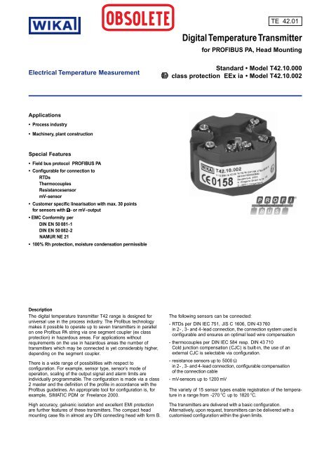
The digital temperature transmitter T42 range is designed for<br />
universal use in the process industry. The Profibus technology<br />
makes it possible to operate up to seven transmitters in parallel<br />
on one Profibus PA string via one segment coupler (ex class<br />
protection) in hazardous areas. For applications without<br />
requirements on the use in hazardous areas the number of<br />
transmitters which may be connected is yet considerably higher,<br />
depending on the segment coupler.<br />
There is a wide range of possibilities with respect to<br />
configuration. For example, sensor type, sensor’s mode of<br />
operation, scaling of the output signal and alarm limits are<br />
individually programmable. The configuration is made via a class<br />
2 master and the definition of the profile in accordance with the<br />
Profibus guidelines. An appropriate tool for configuration is, for<br />
example, SIMATIC PDM or Freelance 2000.<br />
High accuracy, galvanic isolation and excellent EMI protection<br />
are further features of these transmitters. The compact head<br />
mounting case fits in almost any DIN connecting head with form B.<br />
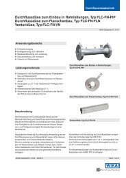
TE 42.01<br />
<strong>Digital</strong> <strong>Temperature</strong> <strong>Transmitter</strong><br />
for PROFIBUS PA, Head Mounting<br />
Standard • Model T42.10.000<br />
class protection EEx ia Model T42.10.002<br />
The following sensors can be connected:<br />
- RTDs per DIN IEC 751, JIS C 1606, DIN 43 760<br />
in 2 - , 3 - and 4 - lead connection, the connection system used is<br />
configurable and ensures an optimal lead wire compensation<br />
- thermocouples per DIN IEC 584 resp. DIN 43 710<br />
Cold junction compensation ( CJC ) is built-in, the use of an<br />
external CJC is selectable via configuration.<br />
- resistance sensors up to 5000 Ω<br />
in 2 - , 3 - and 4 - lead connection, configurable compensation<br />
of the connection cable<br />
- mV-sensors up to 1200 mV<br />
The variety of 15 sensor types enable registration of the temperature<br />
in a range from -270 °C up to 1820 °C.<br />
The transmitters are delivered with a basic configuration.<br />
Alternatively, upon request, transmitters can be delivered with a<br />
customised configuration within the given limits.
Specifications Model T42.10.000 / T42.10.002<br />
Input configurable: type of sensor and measuring range Measuring range<br />
RTDs Pt100 ( α = 0,00385) DIN IEC 751<br />
1)<br />
-200 ... + 850 °C<br />
JPt100 ( α<br />
=0,003916)JIS C 1606 (1989) -200 ... + 500 °C<br />
Ni100 DIN 43 760 (1987-09) -60 ... + 250 °C<br />
thermocouples type T, Cu-CuNi DIN IEC 584 -270 ... + 400 °C<br />
type E, NiCr-CuNi DIN IEC 584 -270 ... +1000 °C<br />
type J, Fe-CuNi DIN IEC 584 -210 ... +1200 °C<br />
type L, Fe-CuNi DIN 43 710 (1985-12) -200 ... + 900 °C<br />
type K, NiCr-Ni DIN IEC 584 -270 ... +1372 °C<br />
type N, NiCrSi-NiSi DIN IEC 584 -270 ... +1300 °C<br />
type U, Cu-CuNi DIN 43 710 (1985-12) -200 ... + 600 °C<br />
type R, PtRh-Pt DIN IEC 584 -50 ... +1768 °C<br />
type S, PtRh-Pt DIN IEC 584 -50 ... +1768 °C<br />
type B, PtRh-PtRh DIN IEC 584 0 ... +1820 °C<br />
resistance sensor 0 ... 700 Ω<br />
0 ... 1400 Ω<br />
0 ... 2900 Ω<br />
0 ... 5000 Ω<br />
mV-sensor - 140 ... + 140 mV<br />
- 290 ... + 290 mV<br />
- 400 ... + 590 mV<br />
- 400 ... + 1200 mV<br />
RTD / resistance sensor<br />
2<br />
measuring deviation per DIN IEC 770, 23 °C ± 5 K<br />
RTDs MV ≤ 200 °C ± 0.08 K<br />
MV > 200 °C ± ( 0.08 K + 0.01 % (MV - 200 K) )<br />
resistance-sensor ± 0.03 Ω or 0,01 % MV , whichever is greater<br />
sensor current approx. 0.2 mA<br />
temperature coefficient TC RTDs ± ( 0.05 K + 0.015 % MV ) / 10 K Tamb<br />
resistance-sensor ± ( 0.01 Ω + 0.01 % MV ) / 10 K Tamb<br />
lead wire connection configurable: 2-lead , 3-lead , 4-lead<br />
connection leads effect ± 0.02 Ω / 10 Ω<br />
max. permissible resistance 30 Ω each lead, 3-lead symmetric<br />
thermocouples<br />
measuring deviation per DIN IEC 770, 23 °C ± 5 K<br />
type T, L, U -150 °C < MV ≤ 0 °C ± ( 0.25 K + 0.15 % MV )<br />
MV > 0 °C ± ( 0.25 K + 0.015 % MV )<br />
E, J, K, N -150 °C < MV ≤ 0 °C ± ( 0.4 K + 0.2 % MV )<br />
MV > 0 °C ± ( 0.4 K + 0.03 % MV )<br />
R, S 50 °C < MV ≤ 400 °C ± ( 1.2 K + 0.1 % (MV - 400 K) )<br />
400 °C < MV ≤ 1600 °C ± ( 1.2 K + 0.015 % (MV - 400 K) )<br />
B 400 °C < MV ≤ 1000 °C ± ( 1.3 K + 0.25 % (MV - 1000 K) )<br />
MV > 1000 °C ± 1.3 K<br />
additional error of cold junction compensation<br />
at 23 °C ± 5 K<br />
± 0.8 K<br />
temperature coefficient TC type T, L, U MV > -150 °C ± ( 0.1 K + 0.02 % MV ) / 10 K Tamb<br />
E, J, K, N MV > -150 °C ± ( 0.1 K + 0.035 % MV ) / 10 K Tamb<br />
R, S 50 °C < MV ≤ 1600 °C ± ( 0.3 K + 0.025 % (MV - 400 K) ) / 10 K<br />
B MV > 400 °C ± ( 0.4 K + 0.02 % (MV - 1000 K) ) / 10 K<br />
temperature coefficient TC of cold junction compensation ± 0.1 K / 10 K Tamb<br />
connection leads effect ± 0.1 µV / 10 Ω<br />
max. permissible resistance 250 Ω<br />
mV-sensor<br />
measuring deviation per DIN IEC 770, 23 °C ± 5 K ± ( 10 µV + 0.03 % MV )<br />
temperature coefficient TC ± ( 2 µV + 0.03 % MV ) / 10 K<br />
connection leads effect ± 0.1 µV / 10 Ω<br />
max. permissible resistance 250 Ω<br />
Communication PROFIBUS PA , Profile 2.0<br />
bus voltage EN 61158-2/94<br />
model T42.10.000 (without Ex-protection) DC 9 … 32 V<br />
models T42.10.002 (with -protection) DC 9 … 25 V<br />
bus connection reverse polarity possible<br />
max. current consumption 12.8 mA<br />
default address 126<br />
MV measuring value ( temperature measuring values in °C ) Tamb ambient temperature TC temperature coefficient 1) increased up to 1000 °C<br />
Tamb<br />
Tamb<br />
Tamb
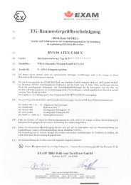
-protection EC Type Examination Certificate DMT 99 ATEX E 033 X<br />
model T42.10.002 II 1G EEx ia IIB / IIC T4 / T5 / T6<br />
permissible ambient temperature -50 °C … +85 °C with T4<br />
-50 °C … +70 °C with T5<br />
maximum values for connection<br />
of the bus ( connections + and – )<br />
suited to connect a power supply<br />
acc. to FISCO-Model with<br />
maximum values as listed<br />
maximum values for connection of the<br />
sensor circuit ( connections 1 up to 4 )<br />
-50 °C … +50 °C with T6<br />
U i = 25 V L i = negligible C i = negligible<br />
Power supply with trapezoid characteristic:<br />
U 0 = 24 V I 0 = 250 mA P 0 = 1.2 W<br />
Power supply with square wave characteristic:<br />
U 0 = 17.5 V I 0 = 280 mA P 0 = 4.9 W<br />
U o = 8.6 V I o = 10 mA P o = 22 mW<br />
Group II B: C o = 40 µF L o = 10 mH<br />
Group II C: C o = 5 µF L o = 10 mH<br />
TE 42.01<br />
Electromagnetic compatibility (EMC)<br />
Special features<br />
- Conformity per DIN EN 50081-1 (March 93) and DIN EN 50082-2 (February 96)<br />
NAMUR NE 21 (May 93)<br />
isolation voltage (input versus bus connection)<br />
ambient and storage temperature<br />
AC 1500 V, 60 s<br />
standard range -40 … +85 °C<br />
climate class Cx (-40 ... +85 °C, 5 % up to 95 % relative humidity) DIN EN 60 654-1<br />
maximum permissible humidity 100 % relative humidity (unlimited with isolated connection wires),<br />
moisture condensation permissible DIN IEC 68-2-30 Var. 2<br />
vibration 10 … 2000 Hz 5 g DIN IEC 68-2-6<br />
shock DIN IEC 68-2-27<br />
salt fog DIN IEC 68-2-11 g N = 30<br />
warm-up time approx. 5 Min. 1)<br />
measured value update approx. 2.5 / s<br />
temperature units configurable: K, °C, °F, °R<br />
configuration and calibration data permanently stored in EEPROM<br />
testing current to monitor sensor nom. 1 µA during testing cycle, otherwise 0 µA<br />
self-monitoring automatic execution of initial test after connection to power supply,<br />
thereafter monitoring for internal malfunction<br />
Case head mounting design<br />
material plastic<br />
ingress protection case IP 66 / IP 67 IEC 529 / EN 60529<br />
terminal connections IP 00 IEC 529 / EN 60529<br />
cross section of terminal connections max. 2.5 mm² , screws captive<br />
weight approx. 70 g<br />
dimensions see drawings<br />
1) Time, after turn on, until the instrument will function within specified repeatability<br />
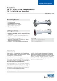
Dimensions in mm Accessories<br />
Mounting material<br />
3209 482.01<br />
To use for mounting<br />
- in the top of a connection head<br />
- on a measuring insert, spring-loaded<br />
- on a standard rail<br />
3
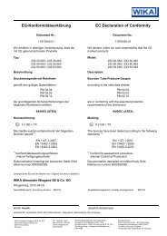
Designation of terminal connectors<br />
CJC with<br />
external Pt 100<br />
thermocouple<br />
Wiring scheme<br />
PROFIBUS DP<br />
45.45 kbps or 93.75 kbps<br />
dependent upon segment coupler<br />
Input<br />
RTD / resistance sensor<br />
in<br />
4-lead 3-lead 2-lead<br />
further<br />
PROFIBUS DP instruments<br />
Field No. Code Features<br />
Order code:<br />
3204 073.01<br />
1 2 3<br />
T42.10 – 00 – –<br />
Additional text:<br />
Segment coupler ( Ex )<br />
Power supply<br />
Segment coupler ( Non-Ex )<br />
Power supply<br />
mV - sensor<br />
Ordering information for temperature transmitter Model T42<br />
Specifications and dimensions given in this leaflet represent the state of engineering at the time of printing.<br />
Modifications may take place and materials specified may be replaced by others without prior notice.<br />
<strong>WIKA</strong> <strong>Alexander</strong> <strong>Wiegand</strong> GmbH & Co. KG<br />
<strong>Alexander</strong>-<strong>Wiegand</strong>-Straße . 63911 Klingenberg<br />
Tel.: (0 93 72) 132 - 0 . Fax: (0 93 72) 132 - 406<br />
http://www.wika.de . E-mail: info@wika.de<br />
PROFIBUS PA<br />
Safe area Hazardous area<br />
2227 215.01<br />
PROFIBUS PA<br />
Field bus<br />
Explosion protection<br />
0 without<br />
1 2 II 1G EEx ia IIC T4/T5/T6<br />
Measuring range<br />
PB basic configuration 1)<br />
2 PK customer’s specification 2) please state as additional text<br />
Additional order info<br />
YES NO<br />
3 T Z additional text Please state as clearly understandable text !<br />
PROFIBUS PA<br />
further transmitters T42<br />
or other PROFIBUS PA instruments<br />
further transmitters T42<br />
or other PROFIBUS PA instruments<br />
1) Pt 100, 3 wire, 0 ... 150 °C<br />
2) Please pay attention to the limits of measuring ranges on page 2.<br />
9035923 10/2005 GB