8. Diagnostics Chart with Trouble Code by ABS ... - JustAnswer
8. Diagnostics Chart with Trouble Code by ABS ... - JustAnswer
8. Diagnostics Chart with Trouble Code by ABS ... - JustAnswer

Create successful ePaper yourself
Turn your PDF publications into a flip-book with our unique Google optimized e-Paper software.
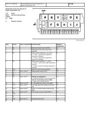
4-4 [T8A0] DIAGNOSTICS<br />
<strong>8.</strong> <strong>Diagnostics</strong> <strong>Chart</strong> <strong>with</strong> <strong>Trouble</strong> <strong>Code</strong> <strong>by</strong> <strong>ABS</strong> Warning Light<br />
<strong>8.</strong> <strong>Diagnostics</strong> <strong>Chart</strong> <strong>with</strong> <strong>Trouble</strong> <strong>Code</strong> <strong>by</strong> <strong>ABS</strong> Warning Light<br />
A: LIST OF TROUBLE CODE<br />
<strong>Trouble</strong> code Contents of diagnosis Ref. to<br />
11<br />
Start code<br />
<strong>Trouble</strong> code is shown after start code.<br />
Only start code is shown in normal condition.<br />
—<br />
21<br />
Front right <strong>ABS</strong> sensor <br />
23 Abnormal <strong>ABS</strong> sensor<br />
Front left <strong>ABS</strong> sensor <br />
25 (Open circuit or input voltage too high)<br />
Rear right <strong>ABS</strong> sensor <br />
27 Rear left <strong>ABS</strong> sensor <br />
22<br />
Front right <strong>ABS</strong> sensor <br />
24<br />
26<br />
28<br />
Abnormal <strong>ABS</strong> sensor<br />
(Abnormal <strong>ABS</strong> sensor signal)<br />
Front left <strong>ABS</strong> sensor<br />
Rear right <strong>ABS</strong> sensor<br />
Rear left <strong>ABS</strong> sensor<br />
<br />
<br />
<br />
29 Any one of four <br />
31<br />
Front right inlet valve <br />
32 Front right outlet valve <br />
33 Front left inlet valve <br />
34 Abnormal solenoid valve circuit(s) in <strong>ABS</strong> control Front left outlet valve <br />
35 module and hydraulic unit<br />
Rear right inlet valve <br />
36 Rear right outlet valve <br />
37 Rear left inlet valve <br />
38 Rear left outlet valve <br />
41 Abnormal <strong>ABS</strong> control module <br />
42 Source voltage is abnormal. <br />
44 A combination of AT control abnormal <br />
51 Abnormal valve relay <br />
52 Abnormal motor and/or motor relay <br />
54 Abnormal stop light switch <br />
56 Abnormal G sensor output voltage <br />
28
MEMO:<br />
DIAGNOSTICS<br />
[T8A0] 4-4<br />
<strong>8.</strong> <strong>Diagnostics</strong> <strong>Chart</strong> <strong>with</strong> <strong>Trouble</strong> <strong>Code</strong> <strong>by</strong> <strong>ABS</strong> Warning Light<br />
29
4-4 [T8B0] DIAGNOSTICS<br />
<strong>8.</strong> <strong>Diagnostics</strong> <strong>Chart</strong> <strong>with</strong> <strong>Trouble</strong> <strong>Code</strong> <strong>by</strong> <strong>ABS</strong> Warning Light<br />
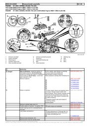
B: TROUBLE CODE 21 (FRONT RH)<br />
C: TROUBLE CODE 23 (FRONT LH)<br />
D: TROUBLE CODE 25 (REAR RH)<br />
E: TROUBLE CODE 27 (REAR LH)<br />
— ABNORMAL <strong>ABS</strong> SENSOR (OPEN CIRCUIT OR INPUT VOLTAGE TOO<br />
HIGH) —<br />
DIAGNOSIS:<br />
Faulty <strong>ABS</strong> sensor (Broken wire, input voltage too high)<br />
Faulty harness connector<br />
TROUBLE SYMPTOM:<br />
<strong>ABS</strong> does not operate.<br />
WIRING DIAGRAM:<br />
30<br />
S4M0282
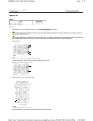
8E1 : CHECK <strong>ABS</strong> SENSOR.<br />
DIAGNOSTICS<br />
1) Turn ignition switch to OFF.<br />
2) Disconnect connector from <strong>ABS</strong> sensor.<br />
3) Measure resistance of <strong>ABS</strong> sensor connector<br />
terminals.<br />
Terminal<br />
Front RH No. 1 — No. 2:<br />
Front LH No. 1 — No. 2:<br />
Rear RH No. 1 — No. 2:<br />
Rear LH No. 1 — No. 2:<br />
B4M0806<br />
: Is the resistance between 0.8 and 1.2<br />
kΩ?<br />
: Go to step 8E2.<br />
: Replace <strong>ABS</strong> sensor. <br />
[T8E2] 4-4<br />
<strong>8.</strong> <strong>Diagnostics</strong> <strong>Chart</strong> <strong>with</strong> <strong>Trouble</strong> <strong>Code</strong> <strong>by</strong> <strong>ABS</strong> Warning Light<br />
31<br />
8E2 : CHECK BATTERY SHORT OF <strong>ABS</strong><br />
SENSOR.<br />
1) Disconnect connector from <strong>ABS</strong>CM&H/U.<br />
2) Measure voltage between <strong>ABS</strong> sensor and<br />
chassis ground.<br />
Terminal<br />
Front RH No. 1 (+) — Chassis ground (−):<br />
Front LH No. 1 (+) — Chassis ground (−):<br />
Rear RH No. 1 (+) — Chassis ground (−):<br />
Rear LH No. 1 (+) — Chassis ground (−):<br />
B4M0807<br />
: Is the voltage less than 1 V?<br />
: Go to step 8E3.<br />
: Replace <strong>ABS</strong> sensor.
4-4 [T8E3] DIAGNOSTICS<br />
<strong>8.</strong> <strong>Diagnostics</strong> <strong>Chart</strong> <strong>with</strong> <strong>Trouble</strong> <strong>Code</strong> <strong>by</strong> <strong>ABS</strong> Warning Light<br />
8E3 : CHECK BATTERY SHORT OF <strong>ABS</strong><br />
SENSOR.<br />
1) Turn ignition switch to ON.<br />
2) Measure voltage between <strong>ABS</strong> sensor and<br />
chassis ground.<br />
Terminal<br />
Front RH No. 1 (+) — Chassis ground (−):<br />
Front LH No. 1 (+) — Chassis ground (−):<br />
Rear RH No. 1 (+) — Chassis ground (−):<br />
Rear LH No. 1 (+) — Chassis ground (−):<br />
B4M0807<br />
: Is the voltage less than 1 V?<br />
: Go to step 8E4.<br />
: Replace <strong>ABS</strong> sensor. <br />
32<br />
8E4 : CHECK HARNESS/CONNECTOR<br />
BETWEEN <strong>ABS</strong>CM&H/U AND <strong>ABS</strong><br />
SENSOR.<br />
1) Turn ignition switch to OFF.<br />
2) Connect connector to <strong>ABS</strong> sensor.<br />
3) Measure resistance between <strong>ABS</strong>CM&H/U<br />
connector terminals.<br />
Connector & terminal<br />
<strong>Trouble</strong> code 21 / (F49) No. 11 — No. 12:<br />
<strong>Trouble</strong> code 23 / (F49) No. 9 — No. 10:<br />
<strong>Trouble</strong> code 25 / (F49) No. 13 — No. 15:<br />
<strong>Trouble</strong> code 27 / (F49) No. 7 — No. 8:<br />
S4M0283A<br />
: Is the resistance between 0.8 and 1.2<br />
kΩ?<br />
: Go to step 8E5.<br />
: Repair harness/connector between<br />
<strong>ABS</strong>CM&H/U and <strong>ABS</strong> sensor.
DIAGNOSTICS<br />
8E5 : CHECK BATTERY SHORT OF HAR-<br />
NESS.<br />
Measure voltage between <strong>ABS</strong>CM&H/U connector<br />
and chassis ground.<br />
Connector & terminal<br />
<strong>Trouble</strong> code 21 / (F49) No. 11 (+) —<br />
Chassis ground (−):<br />
<strong>Trouble</strong> code 23 / (F49) No. 9 (+) — Chassis<br />
ground (−):<br />
<strong>Trouble</strong> code 25 / (F49) No. 13 (+) —<br />
Chassis ground (−):<br />
<strong>Trouble</strong> code 27 / (F49) No. 7 (+) — Chassis<br />
ground (−):<br />
S4M0284A<br />
: Is the voltage less than 1 V?<br />
: Go to step 8E6.<br />
: Repair harness between <strong>ABS</strong>CM&H/U<br />
and <strong>ABS</strong> sensor.<br />
[T8E7] 4-4<br />
<strong>8.</strong> <strong>Diagnostics</strong> <strong>Chart</strong> <strong>with</strong> <strong>Trouble</strong> <strong>Code</strong> <strong>by</strong> <strong>ABS</strong> Warning Light<br />
33<br />
8E6 : CHECK BATTERY SHORT OF HAR-<br />
NESS.<br />
1) Turn ignition switch to ON.<br />
2) Measure voltage between <strong>ABS</strong>CM&H/U connector<br />
and chassis ground.<br />
Connector & terminal<br />
<strong>Trouble</strong> code 21 / (F49) No. 11 (+) —<br />
Chassis ground (−):<br />
<strong>Trouble</strong> code 23 / (F49) No. 9 (+) — Chassis<br />
ground (−):<br />
<strong>Trouble</strong> code 25 / (F49) No. 13 (+) —<br />
Chassis ground (−):<br />
<strong>Trouble</strong> code 27 / (F49) No. 7 (+) — Chassis<br />
ground (−):<br />
S4M0284A<br />
: Is the voltage less than 1 V?<br />
: Go to step 8E7.<br />
: Repair harness between <strong>ABS</strong>CM&H/U<br />
and <strong>ABS</strong> sensor.<br />
8E7 : CHECK INSTALLATION OF <strong>ABS</strong> SEN-<br />
SOR.<br />
Tightening torque:<br />
32±10 N·m (3.3±1.0 kg-m, 24±7 ft-lb)<br />
: Are the <strong>ABS</strong> sensor installation bolts<br />
tightened securely?<br />
: Go to step 8E<strong>8.</strong><br />
: Tighten <strong>ABS</strong> sensor installation bolts<br />
securely.
4-4 [T8E8] DIAGNOSTICS<br />
<strong>8.</strong> <strong>Diagnostics</strong> <strong>Chart</strong> <strong>with</strong> <strong>Trouble</strong> <strong>Code</strong> <strong>by</strong> <strong>ABS</strong> Warning Light<br />
8E8 : CHECK INSTALLATION OF TONE<br />
WHEEL.<br />
Tightening torque:<br />
13±3 N·m (1.3±0.3 kg-m, 9.4±2.2 ft-lb)<br />
: Are the tone wheel installation bolts<br />
tightened securely?<br />
: Go to step 8E9.<br />
: Tighten tone wheel installation bolts<br />
securely.<br />
8E9 : CHECK <strong>ABS</strong> SENSOR GAP.<br />
Measure tone wheel-to-pole piece gap over entire<br />
perimeter of the wheel.<br />
Specifications<br />
G4M0700<br />
G4M0701<br />
Front wheel Rear wheel<br />
0.9 — 1.4 mm<br />
(0.035 — 0.055<br />
in)<br />
0.7 — 1.2 mm<br />
(0.028 — 0.047<br />
in)<br />
: Is the gap <strong>with</strong>in the specifications?<br />
: Go to step 8E10.<br />
: Adjust the gap.<br />
NOTE:<br />
Adjust the gap using spacers (Part No.<br />
26755AA000). If spacers cannot correct the gap,<br />
replace worn sensor or worn tone wheel.<br />
34<br />
8E10 : CHECK HUB RUNOUT.<br />
Measure hub runout.<br />
: Is the runout less than 0.05 mm<br />
(0.0020 in)?<br />
: Go to step 8E11.<br />
: Repair hub. or<br />
<br />
8E11 : CHECK GROUND SHORT OF <strong>ABS</strong><br />
SENSOR.<br />
1) Turn ignition switch to ON.<br />
2) Measure resistance between <strong>ABS</strong> sensor and<br />
chassis ground.<br />
Terminal<br />
Front RH No. 1 — Chassis ground:<br />
Front LH No. 1 — Chassis ground:<br />
Rear RH No. 1 — Chassis ground:<br />
Rear LH No. 1 — Chassis ground:<br />
B4M0818<br />
: Is the resistance more than 1 MΩ?<br />
: Go to step 8E12.<br />
: Replace <strong>ABS</strong> sensor and <strong>ABS</strong>CM&H/U.<br />
and
DIAGNOSTICS<br />
8E12 : CHECK GROUND SHORT OF HAR-<br />
NESS.<br />
1) Turn ignition switch to OFF.<br />
2) Connect connector to <strong>ABS</strong> sensor.<br />
3) Measure resistance between <strong>ABS</strong>CM&H/U<br />
connector terminal and chassis ground.<br />
Connector & terminal<br />
<strong>Trouble</strong> code 21 / (F49) No. 11 — Chassis<br />
ground:<br />
<strong>Trouble</strong> code 23 / (F49) No. 9 — Chassis<br />
ground:<br />
<strong>Trouble</strong> code 25 / (F49) No. 13 — Chassis<br />
ground:<br />
<strong>Trouble</strong> code 27 / (F49) No. 7 — Chassis<br />
ground:<br />
S4M0285A<br />
: Is the resistance more than 1 MΩ?<br />
: Go to step 8E13.<br />
: Repair harness between <strong>ABS</strong>CM&H/U<br />
and <strong>ABS</strong> sensor.<br />
Replace <strong>ABS</strong>CM&H/U. <br />
8E13 : CHECK POOR CONTACT IN CON-<br />
NECTORS.<br />
: Is there poor contact in connectors<br />
between <strong>ABS</strong>CM&H/U and <strong>ABS</strong> sensor?<br />
<br />
: Repair connector.<br />
: Go to step 8E14.<br />
[T8E15] 4-4<br />
<strong>8.</strong> <strong>Diagnostics</strong> <strong>Chart</strong> <strong>with</strong> <strong>Trouble</strong> <strong>Code</strong> <strong>by</strong> <strong>ABS</strong> Warning Light<br />
35<br />
8E14 : CHECK <strong>ABS</strong>CM&H/U.<br />
1) Connect all connectors.<br />
2) Erase the memory.<br />
3) Perform inspection mode.<br />
4) Read out the trouble code.<br />
: Is the same trouble code as in the<br />
current diagnosis still being output?<br />
: Replace <strong>ABS</strong>CM&H/U. <br />
: Go to step 8E15.<br />
8E15 : CHECK ANY OTHER TROUBLE<br />
CODES APPEARANCE.<br />
: Are other trouble codes being output?<br />
: Proceed <strong>with</strong> the diagnosis corresponding<br />
to the trouble code.<br />
: A temporary poor contact.<br />
NOTE:<br />
Check harness and connectors between<br />
<strong>ABS</strong>CM&H/U and <strong>ABS</strong> sensor.
4-4 [T8F0] DIAGNOSTICS<br />
<strong>8.</strong> <strong>Diagnostics</strong> <strong>Chart</strong> <strong>with</strong> <strong>Trouble</strong> <strong>Code</strong> <strong>by</strong> <strong>ABS</strong> Warning Light<br />
F: TROUBLE CODE 22 (FRONT RH)<br />
G: TROUBLE CODE 24 (FRONT LH)<br />
H: TROUBLE CODE 26 (REAR RH)<br />
I: TROUBLE CODE 28 (REAR LH)<br />
— ABNORMAL <strong>ABS</strong> SENSOR (ABNORMAL <strong>ABS</strong> SENSOR SIGNAL) —<br />
DIAGNOSIS:<br />
Faulty <strong>ABS</strong> sensor signal (noise, irregular signal, etc.)<br />
Faulty harness/connector<br />
TROUBLE SYMPTOM:<br />
<strong>ABS</strong> does not operate.<br />
WIRING DIAGRAM:<br />
36<br />
S4M0282
8I1 : CHECK INSTALLATION OF <strong>ABS</strong> SEN-<br />
SOR.<br />
Tightening torque:<br />
32±10 N·m (3.3±1.0 kg-m, 24±7 ft-lb)<br />
: Are the <strong>ABS</strong> sensor installation bolts<br />
tightened securely?<br />
: Go to step 8I2.<br />
: Tighten <strong>ABS</strong> sensor installation bolts<br />
securely.<br />
8I2 : CHECK INSTALLATION OF TONE<br />
WHEEL.<br />
DIAGNOSTICS<br />
Tightening torque:<br />
13±3 N·m (1.3±0.3 kg-m, 9.4±2.2 ft-lb)<br />
: Are the tone wheel installation bolts<br />
tightened securely?<br />
: Go to step 8I3.<br />
: Tighten tone wheel installation bolts<br />
securely.<br />
[T8I4] 4-4<br />
<strong>8.</strong> <strong>Diagnostics</strong> <strong>Chart</strong> <strong>with</strong> <strong>Trouble</strong> <strong>Code</strong> <strong>by</strong> <strong>ABS</strong> Warning Light<br />
37<br />
8I3 : CHECK <strong>ABS</strong> SENSOR GAP.<br />
Measure tone wheel to pole piece gap over entire<br />
perimeter of the wheel.<br />
Specifications<br />
G4M0700<br />
G4M0701<br />
Front wheel Rear wheel<br />
0.9 — 1.4 mm<br />
(0.035 — 0.055<br />
in)<br />
0.7 — 1.2 mm<br />
(0.028 — 0.047<br />
in)<br />
: Is the gap <strong>with</strong>in the specifications?<br />
: Go to step 8I4.<br />
: Adjust the gap.<br />
NOTE:<br />
Adjust the gap using spacer (Part No.<br />
26755AA000). If spacers cannot correct the gap,<br />
replace worn sensor or worn tone wheel.<br />
8I4 : CHECK OSCILLOSCOPE.<br />
: Is an oscilloscope available?<br />
: Go to step 8I5.<br />
: Go to step 8I6.
4-4 [T8I5] DIAGNOSTICS<br />
<strong>8.</strong> <strong>Diagnostics</strong> <strong>Chart</strong> <strong>with</strong> <strong>Trouble</strong> <strong>Code</strong> <strong>by</strong> <strong>ABS</strong> Warning Light<br />
8I5 : CHECK <strong>ABS</strong> SENSOR SIGNAL.<br />
1) Raise all four wheels of ground.<br />
2) Turn ignition switch OFF.<br />
3) Connect the oscilloscope to the connector.<br />
4) Turn ignition switch ON.<br />
5) Rotate wheels and measure voltage at specified<br />
frequency.<br />
NOTE:<br />
When this inspection is completed, the<br />
<strong>ABS</strong>CM&H/U sometimes stores the trouble code<br />
29.<br />
Connector & terminal<br />
<strong>Trouble</strong> code 22 / (B100) No. 5 (+) — No.<br />
14 (−):<br />
<strong>Trouble</strong> code 24 / (B100) No. 7 (+) — No.<br />
16 (−):<br />
<strong>Trouble</strong> code 26 / (F55) No. 6 (+) — No. 7<br />
(−):<br />
<strong>Trouble</strong> code 28 / (F55) No. 1 (+) — No. 2<br />
(−):<br />
Specified voltage: 0.12 —1V(When it is<br />
20 Hz.)<br />
S4M0286A<br />
: Is oscilloscope pattern smooth, as<br />
shown in figure?<br />
: Go to step 8I9.<br />
: Go to step 8I6.<br />
38<br />
8I6 : CHECK CONTAMINATION OF <strong>ABS</strong><br />
SENSOR OR TONE WHEEL.<br />
Remove disc rotor or drum from hub in accordance<br />
<strong>with</strong> trouble code.<br />
: Is the <strong>ABS</strong> sensor pole piece or the<br />
tone wheel contaminated <strong>by</strong> dirt or<br />
other foreign matter?<br />
: Thoroughly remove dirt or other foreign<br />
matter.<br />
: Go to step 8I7.<br />
8I7 : CHECK DAMAGE OF <strong>ABS</strong> SENSOR<br />
OR TONE WHEEL.<br />
: Are there broken or damaged in the<br />
<strong>ABS</strong> sensor pole piece or the tone<br />
wheel?<br />
: Replace <strong>ABS</strong> sensor or tone wheel.<br />
, or <br />
: Go to step 8I<strong>8.</strong><br />
8I8 : CHECK HUB RUNOUT.<br />
Measure hub runout.<br />
: Is the runout less than 0.05 mm<br />
(0.0020 in)?<br />
: Go to step 8I9.<br />
: Repair hub. and<br />
DIAGNOSTICS<br />
8I9 : CHECK RESISTANCE OF <strong>ABS</strong> SEN-<br />
SOR.<br />
1) Turn ignition switch OFF.<br />
2) Disconnect connector from <strong>ABS</strong> sensor.<br />
3) Measure resistance between <strong>ABS</strong> sensor connector<br />
terminals.<br />
Terminal<br />
Front RH No. 1 — No. 2:<br />
Front LH No. 1 — No. 2:<br />
Rear RH No. 1 — No. 2:<br />
Rear LH No. 1 — No. 2:<br />
B4M0806<br />
: Is the resistance between 0.8 and 1.2<br />
kΩ?<br />
: Go to step 8I10.<br />
: Replace <strong>ABS</strong> sensor. <br />
[T8I10] 4-4<br />
<strong>8.</strong> <strong>Diagnostics</strong> <strong>Chart</strong> <strong>with</strong> <strong>Trouble</strong> <strong>Code</strong> <strong>by</strong> <strong>ABS</strong> Warning Light<br />
39<br />
8I10 : CHECK GROUND SHORT OF <strong>ABS</strong><br />
SENSOR.<br />
Measure resistance between <strong>ABS</strong> sensor and<br />
chassis ground.<br />
Terminal<br />
Front RH No. 1 — Chassis ground:<br />
Front LH No. 1 — Chassis ground:<br />
Rear RH No. 1 — Chassis ground:<br />
Rear LH No. 1 — Chassis ground:<br />
B4M0818<br />
: Is the resistance more than 1 MΩ?<br />
: Go to step 8I11.<br />
: Replace <strong>ABS</strong> sensor.
4-4 [T8I11] DIAGNOSTICS<br />
<strong>8.</strong> <strong>Diagnostics</strong> <strong>Chart</strong> <strong>with</strong> <strong>Trouble</strong> <strong>Code</strong> <strong>by</strong> <strong>ABS</strong> Warning Light<br />
8I11 : CHECK HARNESS/CONNECTOR<br />
BETWEEN <strong>ABS</strong>CM&H/U AND <strong>ABS</strong><br />
SENSOR.<br />
1) Connect connector to <strong>ABS</strong> sensor.<br />
2) Disconnect connector from <strong>ABS</strong>CM&H/U.<br />
3) Measure resistance at <strong>ABS</strong>CM&H/U connector<br />
terminals.<br />
Connector & terminal<br />
<strong>Trouble</strong> code 22 / (F49) No. 11 — No. 12:<br />
<strong>Trouble</strong> code 24 / (F49) No. 9 — No. 10:<br />
<strong>Trouble</strong> code 26 / (F49) No. 13 — No. 15:<br />
<strong>Trouble</strong> code 28 / (F49) No. 7 — No. 8:<br />
S4M0283A<br />
: Is the resistance between 0.8 and 1.2<br />
kΩ?<br />
: Go to step 8I12.<br />
: Repair harness/connector between<br />
<strong>ABS</strong>CM&H/U and <strong>ABS</strong> sensor.<br />
40<br />
8I12 : CHECK GROUND SHORT OF HAR-<br />
NESS.<br />
Measure resistance between <strong>ABS</strong>CM&H/U connector<br />
and chassis ground.<br />
Connector & terminal<br />
<strong>Trouble</strong> code 22 / (F49) No. 11 — Chassis<br />
ground:<br />
<strong>Trouble</strong> code 24 / (F49) No. 9 — Chassis<br />
ground:<br />
<strong>Trouble</strong> code 26 / (F49) No. 13 — Chassis<br />
ground:<br />
<strong>Trouble</strong> code 28 / (F49) No. 7 — Chassis<br />
ground:<br />
S4M0285A<br />
: Is the resistance more than 1 MΩ?<br />
: Go to step 8I13.<br />
: Repair harness/connector between<br />
<strong>ABS</strong>CM&H/U and <strong>ABS</strong> sensor.<br />
8I13 : CHECK GROUND CIRCUIT OF<br />
<strong>ABS</strong>CM&H/U.<br />
Measure resistance between <strong>ABS</strong>CM&H/U and<br />
chassis ground.<br />
Connector & terminal<br />
(F49) No. 23 — GND:<br />
B4M1243A<br />
: Is the resistance less than 0.5 Ω?<br />
: Go to step 8I14.<br />
: Repair <strong>ABS</strong>CM&H/U ground harness.
8I14 : CHECK POOR CONTACT IN CON-<br />
NECTORS.<br />
: Is there poor contact in connectors<br />
between <strong>ABS</strong>CM&H/U and <strong>ABS</strong> sensor?<br />
<br />
: Repair connector.<br />
: Go to step 8I15.<br />
8I15 : CHECK SOURCES OF SIGNAL<br />
NOISE.<br />
: Is the car telephone or the wireless<br />
transmitter properly installed?<br />
: Go to step 8I16.<br />
: Properly install the car telephone or the<br />
wireless transmitter.<br />
8I16 : CHECK SOURCES OF SIGNAL<br />
NOISE.<br />
DIAGNOSTICS<br />
: Are noise sources (such as an<br />
antenna) installed near the sensor<br />
harness?<br />
: Install the noise sources apart from the<br />
sensor harness.<br />
: Go to step 8I17.<br />
[T8I18] 4-4<br />
<strong>8.</strong> <strong>Diagnostics</strong> <strong>Chart</strong> <strong>with</strong> <strong>Trouble</strong> <strong>Code</strong> <strong>by</strong> <strong>ABS</strong> Warning Light<br />
41<br />
8I17 : CHECK SHIELD CIRCUIT.<br />
1) Connect all connectors.<br />
2) Measure resistance between shield connector<br />
and chassis ground.<br />
Connector & terminal<br />
<strong>Trouble</strong> code 22 / (B100) No. 15 — Chassis<br />
ground:<br />
<strong>Trouble</strong> code 24 / (B100) No. 6 — Chassis<br />
ground:<br />
<strong>Trouble</strong> code 26 / (F55) No. 8 — Chassis<br />
ground:<br />
<strong>Trouble</strong> code 28 / (F55) No. 3 — Chassis<br />
ground:<br />
S4M0287A<br />
: Is the resistance less than 0.5 Ω?<br />
: Go to step 8I1<strong>8.</strong><br />
: Repair shield harness.<br />
8I18 : CHECK <strong>ABS</strong>CM&H/U.<br />
1) Connect all connectors.<br />
2) Erase the memory.<br />
3) Perform inspection mode.<br />
4) Read out the trouble code.<br />
: Is the same trouble code as in the<br />
current diagnosis still being output?<br />
: Replace <strong>ABS</strong>CM&H/U. <br />
: Go to step 8I19.
4-4 [T8I19] DIAGNOSTICS<br />
<strong>8.</strong> <strong>Diagnostics</strong> <strong>Chart</strong> <strong>with</strong> <strong>Trouble</strong> <strong>Code</strong> <strong>by</strong> <strong>ABS</strong> Warning Light<br />
8I19 : CHECK ANY OTHER TROUBLE<br />
CODES APPEARANCE.<br />
: Are other trouble codes being output?<br />
: Proceed <strong>with</strong> the diagnosis corresponding<br />
to the trouble code.<br />
: A temporary noise interference.<br />
42
MEMO:<br />
DIAGNOSTICS<br />
[T8I19] 4-4<br />
<strong>8.</strong> <strong>Diagnostics</strong> <strong>Chart</strong> <strong>with</strong> <strong>Trouble</strong> <strong>Code</strong> <strong>by</strong> <strong>ABS</strong> Warning Light<br />
43
4-4 [T8J0] DIAGNOSTICS<br />
<strong>8.</strong> <strong>Diagnostics</strong> <strong>Chart</strong> <strong>with</strong> <strong>Trouble</strong> <strong>Code</strong> <strong>by</strong> <strong>ABS</strong> Warning Light<br />
J: TROUBLE CODE 29<br />
— ABNORMAL <strong>ABS</strong> SENSOR SIGNAL (ANY ONE OF FOUR) —<br />
DIAGNOSIS:<br />
Faulty <strong>ABS</strong> sensor signal (noise, irregular signal, etc.)<br />
Faulty tone wheel<br />
Wheels turning freely for a long time<br />
TROUBLE SYMPTOM:<br />
<strong>ABS</strong> does not operate.<br />
WIRING DIAGRAM:<br />
44<br />
S4M0282
8J1 : CHECK IF THE WHEELS HAVE<br />
TURNED FREELY FOR A LONG TIME.<br />
: Check if the wheels have been turned<br />
freely for more than one minute, such<br />
as when the vehicle is jacked-up,<br />
under full-lock cornering or when tire<br />
is not in contact <strong>with</strong> road surface.<br />
: The <strong>ABS</strong> is normal. Erase the trouble<br />
code. <br />
NOTE:<br />
When the wheels turn freely for a long time, such<br />
as when the vehicle is towed or jacked-up, or when<br />
steering wheel is continuously turned all the way,<br />
this trouble code may sometimes occur.<br />
: Go to step 8J2.<br />
8J2 : CHECK TIRE SPECIFICATIONS.<br />
: Are the tire specifications correct?<br />
: Go to step 8J3.<br />
: Replace tire. <br />
8J3 : CHECK WEAR OF TIRE.<br />
: Is the tire worn excessively?<br />
: Replace tire. <br />
: Go to step 8J4.<br />
8J4 : CHECK TIRE PRESSURE.<br />
: Is the tire pressure correct?<br />
: Go to step 8J5.<br />
: Adjust tire pressure.<br />
DIAGNOSTICS<br />
8J5 : CHECK INSTALLATION OF <strong>ABS</strong> SEN-<br />
SOR.<br />
Tightening torque:<br />
32±10 N·m (3.3±1.0 kg-m, 24±7 ft-lb)<br />
: Are the <strong>ABS</strong> sensor installation bolts<br />
tightened securely?<br />
: Go to step 8J6.<br />
: Tighten <strong>ABS</strong> sensor installation bolts<br />
securely.<br />
[T8J7] 4-4<br />
<strong>8.</strong> <strong>Diagnostics</strong> <strong>Chart</strong> <strong>with</strong> <strong>Trouble</strong> <strong>Code</strong> <strong>by</strong> <strong>ABS</strong> Warning Light<br />
45<br />
8J6 : CHECK INSTALLATION OF TONE<br />
WHEEL.<br />
Tightening torque:<br />
13±3 N·m (1.3±0.3 kg-m, 9.4±2.2 ft-lb)<br />
: Are the tone wheel installation bolts<br />
tightened securely?<br />
: Go to step 8J7.<br />
: Tighten tone wheel installation bolts<br />
securely.<br />
8J7 : CHECK <strong>ABS</strong> SENSOR GAP.<br />
Measure tone wheel to pole piece gap over entire<br />
perimeter of the wheel.<br />
Specifications<br />
G4M0700<br />
G4M0701<br />
Front wheel Rear wheel<br />
0.9 — 1.4 mm<br />
(0.035 — 0.055<br />
in)<br />
0.7 — 1.2 mm<br />
(0.028 — 0.047<br />
in)<br />
: Is the gap <strong>with</strong>in the specifications?<br />
: Go to step 8J<strong>8.</strong><br />
: Adjust the gap.<br />
NOTE:<br />
Adjust the gap using spacer (Part No.<br />
26755AA000). If spacers cannot correct the gap,<br />
replace worn sensor or worn tone wheel.
4-4 [T8J8] DIAGNOSTICS<br />
<strong>8.</strong> <strong>Diagnostics</strong> <strong>Chart</strong> <strong>with</strong> <strong>Trouble</strong> <strong>Code</strong> <strong>by</strong> <strong>ABS</strong> Warning Light<br />
8J8 : CHECK OSCILLOSCOPE.<br />
: Is an oscilloscope available?<br />
: Go to step 8J9.<br />
: Go to step 8J10.<br />
8J9 : CHECK <strong>ABS</strong> SENSOR SIGNAL.<br />
1) Raise all four wheels of ground.<br />
2) Turn ignition switch OFF.<br />
3) Connect the oscilloscope to the connector.<br />
4) Turn ignition switch ON.<br />
5) Rotate wheels and measure voltage at specified<br />
frequency.<br />
NOTE:<br />
When this inspection is completed, the <strong>ABS</strong> control<br />
module sometimes stores the trouble code 29.<br />
Connector & terminal<br />
(B100) No. 5 (+) — No. 14 (−) (Front RH):<br />
(B100) No. 7 (+) — No. 16 (−) (Front LH):<br />
(F55) No. 6 (+) — No. 7 (−) (Rear RH):<br />
(F55) No. 1 (+) — No. 2 (−) (Rear LH):<br />
Specified voltage: 0.12 —1V(When it is<br />
20 Hz.)<br />
S4M0286A<br />
: Is oscilloscope pattern smooth, as<br />
shown in figure?<br />
: Go to step 8J13.<br />
: Go to step 8J10.<br />
46<br />
8J10 : CHECK CONTAMINATION OF <strong>ABS</strong><br />
SENSOR OR TONE WHEEL.<br />
Remove disc rotor from hub.<br />
: Is the <strong>ABS</strong> sensor pole piece or the<br />
tone wheel contaminated <strong>by</strong> dirt or<br />
other foreign matter?<br />
: Thoroughly remove dirt or other foreign<br />
matter.<br />
: Go to step 8J11.<br />
8J11 : CHECK DAMAGE OF <strong>ABS</strong> SENSOR<br />
OR TONE WHEEL.<br />
: Are there broken or damaged teeth in<br />
the <strong>ABS</strong> sensor pole piece or the tone<br />
wheel?<br />
: Replace <strong>ABS</strong> sensor or tone wheel.<br />
, or <br />
: Go to step 8J12.<br />
8J12 : CHECK HUB RUNOUT.<br />
Measure hub runout.<br />
: Is the runout less than 0.05 mm<br />
(0.0020 in)?<br />
: Go to step 8J13.<br />
: Repair hub. and<br />
<br />
8J13 : CHECK <strong>ABS</strong>CM&H/U.<br />
1) Turn ignition switch to OFF.<br />
2) Connect all connectors.<br />
3) Erase the memory.<br />
4) Perform inspection mode.<br />
5) Read out the trouble code.<br />
: Is the same trouble code as in the<br />
current diagnosis still being output?<br />
: Replace <strong>ABS</strong>CM&H/U. <br />
: Go to step 8J14.
8J14 : CHECK ANY OTHER TROUBLE<br />
CODES APPEARANCE.<br />
DIAGNOSTICS<br />
: Are other trouble codes being output?<br />
: Proceed <strong>with</strong> the diagnosis corresponding<br />
to the trouble code.<br />
: A temporary poor contact.<br />
[T8J14] 4-4<br />
<strong>8.</strong> <strong>Diagnostics</strong> <strong>Chart</strong> <strong>with</strong> <strong>Trouble</strong> <strong>Code</strong> <strong>by</strong> <strong>ABS</strong> Warning Light<br />
47
4-4 [T8K0] DIAGNOSTICS<br />
<strong>8.</strong> <strong>Diagnostics</strong> <strong>Chart</strong> <strong>with</strong> <strong>Trouble</strong> <strong>Code</strong> <strong>by</strong> <strong>ABS</strong> Warning Light<br />
K: TROUBLE CODE 31 (FRONT RH)<br />
L: TROUBLE CODE 33 (FRONT LH)<br />
M: TROUBLE CODE 35 (REAR RH)<br />
N: TROUBLE CODE 37 (REAR LH)<br />
— ABNORMAL INLET SOLENOID VALVE CIRCUIT(S) IN <strong>ABS</strong>CM&H/U —<br />
DIAGNOSIS:<br />
Faulty harness/connector<br />
Faulty inlet solenoid valve in <strong>ABS</strong>CM&H/U<br />
TROUBLE SYMPTOM:<br />
<strong>ABS</strong> does not operate.<br />
WIRING DIAGRAM:<br />
48<br />
S4M0067
8N1 : CHECK INPUT VOLTAGE OF<br />
<strong>ABS</strong>CM&H/U.<br />
1) Disconnect connector from <strong>ABS</strong>CM&H/U.<br />
2) Run the engine at idle.<br />
3) Measure voltage between <strong>ABS</strong>CM&H/U connector<br />
and chassis ground.<br />
Connector & terminal<br />
(F49) No. 1 (+) — Chassis ground (−):<br />
B4M1234A<br />
: Is the voltage between 10 V and 15 V?<br />
: Go to step 8N2.<br />
: Repair harness connector between<br />
battery, ignition switch and<br />
<strong>ABS</strong>CM&H/U.<br />
8N2 : CHECK GROUND CIRCUIT OF<br />
<strong>ABS</strong>CM&H/U.<br />
DIAGNOSTICS<br />
1) Turn ignition switch to OFF.<br />
2) Measure resistance between <strong>ABS</strong>CM&H/U<br />
connector and chassis ground.<br />
Connector & terminal<br />
(F49) No. 23 — Chassis ground:<br />
B4M1243A<br />
: Is the resistance less than 0.5 Ω?<br />
: Go to step 8N3.<br />
: Repair <strong>ABS</strong>CM&H/U ground harness.<br />
[T8N5] 4-4<br />
<strong>8.</strong> <strong>Diagnostics</strong> <strong>Chart</strong> <strong>with</strong> <strong>Trouble</strong> <strong>Code</strong> <strong>by</strong> <strong>ABS</strong> Warning Light<br />
49<br />
8N3 : CHECK POOR CONTACT IN CON-<br />
NECTORS.<br />
: Is there poor contact in connectors<br />
between generator, battery and<br />
<strong>ABS</strong>CM&H/U? <br />
: Repair connector.<br />
: Go to step 8N4.<br />
8N4 : CHECK <strong>ABS</strong>CM&H/U.<br />
1) Connect all connectors.<br />
2) Erase the memory.<br />
3) Perform inspection mode.<br />
4) Read out the trouble code.<br />
: Is the same trouble code as in the<br />
current diagnosis still being output?<br />
: Replace <strong>ABS</strong>CM&H/U. <br />
: Go to step 8N5.<br />
8N5 : CHECK ANY OTHER TROUBLE<br />
CODES APPEARANCE.<br />
: Are other trouble codes being output?<br />
: Proceed <strong>with</strong> the diagnosis corresponding<br />
to the trouble code.<br />
: A temporary poor contact.
4-4 [T8O0] DIAGNOSTICS<br />
<strong>8.</strong> <strong>Diagnostics</strong> <strong>Chart</strong> <strong>with</strong> <strong>Trouble</strong> <strong>Code</strong> <strong>by</strong> <strong>ABS</strong> Warning Light<br />
O: TROUBLE CODE 32 (FRONT RH)<br />
P: TROUBLE CODE 34 (FRONT LH)<br />
Q: TROUBLE CODE 36 (REAR RH)<br />
R: TROUBLE CODE 38 (REAR LH)<br />
— ABNORMAL OUTLET SOLENOID VALVE CIRCUIT(S) IN <strong>ABS</strong>CM&H/U —<br />
DIAGNOSIS:<br />
Faulty harness/connector<br />
Faulty outlet solenoid valve in <strong>ABS</strong>CM&H/U<br />
TROUBLE SYMPTOM:<br />
<strong>ABS</strong> does not operate.<br />
WIRING DIAGRAM:<br />
50<br />
S4M0067
8R1 : CHECK INPUT VOLTAGE OF<br />
<strong>ABS</strong>CM&H/U.<br />
1) Disconnect connector from <strong>ABS</strong>CM&H/U.<br />
2) Run the engine at idle.<br />
3) Measure voltage between <strong>ABS</strong>CM&H/U connector<br />
and chassis ground.<br />
Connector & terminal<br />
(F49) No. 1 (+) — Chassis ground (−):<br />
B4M1234A<br />
: Is the voltage between 10 V and 15 V?<br />
: Go to step 8R2.<br />
: Repair harness connector between<br />
battery, ignition switch and<br />
<strong>ABS</strong>CM&H/U.<br />
8R2 : CHECK GROUND CIRCUIT OF<br />
<strong>ABS</strong>CM&H/U.<br />
DIAGNOSTICS<br />
1) Turn ignition switch to OFF.<br />
2) Measure resistance between <strong>ABS</strong>CM&H/U<br />
connector and chassis ground.<br />
Connector & terminal<br />
(F49) No. 23 — Chassis ground:<br />
B4M1243A<br />
: Is the resistance less than 0.5 Ω?<br />
: Go to step 8R3.<br />
: Repair <strong>ABS</strong>CM&H/U ground harness.<br />
[T8R5] 4-4<br />
<strong>8.</strong> <strong>Diagnostics</strong> <strong>Chart</strong> <strong>with</strong> <strong>Trouble</strong> <strong>Code</strong> <strong>by</strong> <strong>ABS</strong> Warning Light<br />
51<br />
8R3 : CHECK POOR CONTACT IN CON-<br />
NECTORS.<br />
: Is there poor contact in connectors<br />
between generator, battery and<br />
<strong>ABS</strong>CM&H/U? <br />
: Repair connector.<br />
: Go to step 8R4.<br />
8R4 : CHECK <strong>ABS</strong>CM&H/U.<br />
1) Connect all connectors.<br />
2) Erase the memory.<br />
3) Perform inspection mode.<br />
4) Read out the trouble code.<br />
: Is the same trouble code as in the<br />
current diagnosis still being output?<br />
: Replace <strong>ABS</strong>CM&H/U. <br />
: Go to step 8R5.<br />
8R5 : CHECK ANY OTHER TROUBLE<br />
CODES APPEARANCE.<br />
: Are other trouble codes being output?<br />
: Proceed <strong>with</strong> the diagnosis corresponding<br />
to the trouble code.<br />
: A temporary poor contact.
4-4 [T8S0] DIAGNOSTICS<br />
<strong>8.</strong> <strong>Diagnostics</strong> <strong>Chart</strong> <strong>with</strong> <strong>Trouble</strong> <strong>Code</strong> <strong>by</strong> <strong>ABS</strong> Warning Light<br />
S: TROUBLE CODE 41<br />
— ABNORMAL <strong>ABS</strong> CONTROL MODULE —<br />
DIAGNOSIS:<br />
Faulty <strong>ABS</strong>CM&H/U.<br />
TROUBLE SYMPTOM:<br />
<strong>ABS</strong> does not operate.<br />
WIRING DIAGRAM:<br />
52<br />
B4M1246
8S1 : CHECK GROUND CIRCUIT OF<br />
<strong>ABS</strong>CM&H/U.<br />
1) Turn ignition switch to OFF.<br />
2) Disconnect connector from <strong>ABS</strong>CM&H/U.<br />
3) Measure resistance between <strong>ABS</strong>CM&H/U and<br />
chassis ground.<br />
Connector & terminal<br />
(F49) No. 23 — Chassis ground:<br />
B4M1243A<br />
: Is the resistance less than 0.5 Ω?<br />
: Go to step 8S2.<br />
: Repair <strong>ABS</strong>CM&H/U ground harness.<br />
8S2 : CHECK POOR CONTACT IN CON-<br />
NECTORS.<br />
: Is there poor contact in connectors<br />
between battery, ignition switch and<br />
<strong>ABS</strong>CM&H/U? <br />
: Repair connector.<br />
: Go to step 8S3.<br />
8S3 : CHECK SOURCES OF SIGNAL<br />
NOISE.<br />
DIAGNOSTICS<br />
: Is the car telephone or the wireless<br />
transmitter properly installed?<br />
: Go to step 8S4.<br />
: Properly install the car telephone or the<br />
wireless transmitter.<br />
[T8S6] 4-4<br />
<strong>8.</strong> <strong>Diagnostics</strong> <strong>Chart</strong> <strong>with</strong> <strong>Trouble</strong> <strong>Code</strong> <strong>by</strong> <strong>ABS</strong> Warning Light<br />
53<br />
8S4 : CHECK SOURCES OF SIGNAL<br />
NOISE.<br />
: Are noise sources (such as an<br />
antenna) installed near the sensor<br />
harness?<br />
: Install the noise sources apart from the<br />
sensor harness.<br />
: Go to step 8S5.<br />
8S5 : CHECK <strong>ABS</strong>CM&H/U.<br />
1) Connect all connectors.<br />
2) Erase the memory.<br />
3) Perform inspection mode.<br />
4) Read out the trouble code.<br />
: Is the same trouble code as in the<br />
current diagnosis still being output?<br />
: Replace <strong>ABS</strong>CM&H/U. <br />
: Go to step 8S6.<br />
8S6 : CHECK ANY OTHER TROUBLE<br />
CODES APPEARANCE.<br />
: Are other trouble codes being output?<br />
: Proceed <strong>with</strong> the diagnosis corresponding<br />
to the trouble code.<br />
: A temporary poor contact.
4-4 [T8T0] DIAGNOSTICS<br />
<strong>8.</strong> <strong>Diagnostics</strong> <strong>Chart</strong> <strong>with</strong> <strong>Trouble</strong> <strong>Code</strong> <strong>by</strong> <strong>ABS</strong> Warning Light<br />
T: TROUBLE CODE 42<br />
— SOURCE VOLTAGE IS ABNORMAL. —<br />
DIAGNOSIS:<br />
Power source voltage of the <strong>ABS</strong>CM&H/U is low or high.<br />
TROUBLE SYMPTOM:<br />
<strong>ABS</strong> does not operate.<br />
WIRING DIAGRAM:<br />
54<br />
S4M0067
8T1 : CHECK GENERATOR.<br />
1) Start engine.<br />
2) Idling after warm-up.<br />
3) Measure voltage between generator B terminal<br />
and chassis ground.<br />
Terminal<br />
Generator B terminal — Chassis ground:<br />
B4M0430<br />
: Is the voltage between 10 V and 17 V?<br />
: Go to step 8T2.<br />
: Repair generator. <br />
8T2 : CHECK BATTERY TERMINAL.<br />
DIAGNOSTICS<br />
Turn ignition switch to OFF.<br />
: Are the positive and negative battery<br />
terminals tightly clamped?<br />
: Go to step 8T3.<br />
: Tighten the clamp of terminal.<br />
[T8T4] 4-4<br />
<strong>8.</strong> <strong>Diagnostics</strong> <strong>Chart</strong> <strong>with</strong> <strong>Trouble</strong> <strong>Code</strong> <strong>by</strong> <strong>ABS</strong> Warning Light<br />
55<br />
8T3 : CHECK INPUT VOLTAGE OF<br />
<strong>ABS</strong>CM&H/U.<br />
1) Disconnect connector from <strong>ABS</strong>CM&H/U.<br />
2) Run the engine at idle.<br />
3) Measure voltage between <strong>ABS</strong>CM&H/U connector<br />
and chassis ground.<br />
Connector & terminal<br />
(F49) No. 1 (+) — Chassis ground (−):<br />
B4M1234A<br />
: Is the voltage between 10 V and 17 V?<br />
: Go to step 8T4.<br />
: Repair harness connector between<br />
battery, ignition switch and<br />
<strong>ABS</strong>CM&H/U.<br />
8T4 : CHECK GROUND CIRCUIT OF<br />
<strong>ABS</strong>CM&H/U.<br />
1) Turn ignition switch to OFF.<br />
2) Measure resistance between <strong>ABS</strong>CM&H/U<br />
connector and chassis ground.<br />
Connector & terminal<br />
(F49) No. 23 — Chassis ground:<br />
B4M1243A<br />
: Is the resistance less than 0.5 Ω?<br />
: Go to step 8T5.<br />
: Repair <strong>ABS</strong>CM&H/U ground harness.
4-4 [T8T5] DIAGNOSTICS<br />
<strong>8.</strong> <strong>Diagnostics</strong> <strong>Chart</strong> <strong>with</strong> <strong>Trouble</strong> <strong>Code</strong> <strong>by</strong> <strong>ABS</strong> Warning Light<br />
8T5 : CHECK POOR CONTACT IN CON-<br />
NECTORS.<br />
: Is there poor contact in connectors<br />
between generator, battery and<br />
<strong>ABS</strong>CM&H/U? <br />
: Repair connector.<br />
: Go to step 8T6.<br />
8T6 : CHECK <strong>ABS</strong>CM&H/U.<br />
1) Connect all connectors.<br />
2) Erase the memory.<br />
3) Perform inspection mode.<br />
4) Read out the trouble code.<br />
: Is the same trouble code as in the<br />
current diagnosis still being output?<br />
: Replace <strong>ABS</strong>CM&H/U. <br />
: Go to step 8T7.<br />
8T7 : CHECK ANY OTHER TROUBLE<br />
CODES APPEARANCE.<br />
: Are other trouble codes being output?<br />
: Proceed <strong>with</strong> the diagnosis corresponding<br />
to the trouble code.<br />
: A temporary poor contact.<br />
56
MEMO:<br />
DIAGNOSTICS<br />
[T8T7] 4-4<br />
<strong>8.</strong> <strong>Diagnostics</strong> <strong>Chart</strong> <strong>with</strong> <strong>Trouble</strong> <strong>Code</strong> <strong>by</strong> <strong>ABS</strong> Warning Light<br />
57
4-4 [T8U0] DIAGNOSTICS<br />
<strong>8.</strong> <strong>Diagnostics</strong> <strong>Chart</strong> <strong>with</strong> <strong>Trouble</strong> <strong>Code</strong> <strong>by</strong> <strong>ABS</strong> Warning Light<br />
U: TROUBLE CODE 44<br />
— A COMBINATION OF AT CONTROL ABNORMAL —<br />
DIAGNOSIS:<br />
Combination of AT control faults<br />
TROUBLE SYMPTOM:<br />
<strong>ABS</strong> does not operate.<br />
WIRING DIAGRAM:<br />
58<br />
S4M0288
8U1 : CHECK SPECIFICATIONS OF THE<br />
<strong>ABS</strong>CM&H/U.<br />
Check specifications of the mark to the<br />
<strong>ABS</strong>CM&H/U.<br />
Mark Model<br />
C7 AWD AT<br />
C8 AWD MT<br />
DIAGNOSTICS<br />
S4M0289A<br />
: Is an <strong>ABS</strong>CM&H/U for AT model<br />
installed on a MT model?<br />
: Replace <strong>ABS</strong>CM&H/U. <br />
: Go to step 8U2.<br />
8U2 : CHECK GROUND SHORT OF HAR-<br />
NESS.<br />
1) Turn ignition switch to OFF.<br />
2) Disconnect two connectors from TCM.<br />
3) Disconnect connector from <strong>ABS</strong>CM&H/U.<br />
4) Measure resistance between <strong>ABS</strong>CM&H/U<br />
connector and chassis ground.<br />
Connector & terminal<br />
(F49) No. 3 — Chassis ground:<br />
B4M1249A<br />
: Is the resistance more than 1 MΩ?<br />
: Go to step 8U3.<br />
: Repair harness between TCM and<br />
<strong>ABS</strong>CM&H/U.<br />
[T8U4] 4-4<br />
<strong>8.</strong> <strong>Diagnostics</strong> <strong>Chart</strong> <strong>with</strong> <strong>Trouble</strong> <strong>Code</strong> <strong>by</strong> <strong>ABS</strong> Warning Light<br />
59<br />
8U3 : CHECK BATTERY SHORT OF HAR-<br />
NESS.<br />
Measure voltage between <strong>ABS</strong>CM&H/U connector<br />
and chassis ground.<br />
Connector & terminal<br />
(F49) No. 3 (+) — Chassis ground (−):<br />
B4M1250A<br />
: Is the voltage less than 1 V?<br />
: Go to step 8U4.<br />
: Repair harness between TCM and<br />
<strong>ABS</strong>CM&H/U.<br />
8U4 : CHECK BATTERY SHORT OF HAR-<br />
NESS.<br />
1) Turn ignition switch to ON.<br />
2) Measure voltage between <strong>ABS</strong>CM&H/U connector<br />
and chassis ground.<br />
Connector & terminal<br />
(F49) No. 3 (+) — Chassis ground (−):<br />
B4M1250A<br />
: Is the voltage less than 1 V?<br />
: Go to step 8U5.<br />
: Repair harness between TCM and<br />
<strong>ABS</strong>CM&H/U.
4-4 [T8U5] DIAGNOSTICS<br />
<strong>8.</strong> <strong>Diagnostics</strong> <strong>Chart</strong> <strong>with</strong> <strong>Trouble</strong> <strong>Code</strong> <strong>by</strong> <strong>ABS</strong> Warning Light<br />
8U5 : CHECK TCM.<br />
1) Turn ignition switch to OFF.<br />
2) Connect all connectors to TCM.<br />
3) Turn ignition switch to ON.<br />
4) Measure voltage between TCM connector terminal<br />
and chassis ground.<br />
Connector & terminal<br />
(B54) No. 19 (+) — Chassis ground (−):<br />
S4M0290A<br />
: Is the voltage between 6 V and 15 V?<br />
: Go to step 8U7.<br />
: Go to step 8U6.<br />
8U6 : CHECK AT.<br />
: Is the AT functioning normally?<br />
: Replace TCM. <br />
: Repair AT. <br />
60<br />
8U7 : CHECK OPEN CIRCUIT OF HAR-<br />
NESS.<br />
Measure voltage between <strong>ABS</strong>CM&H/U connector<br />
and chassis ground.<br />
Connector & terminal<br />
(F49) No. 3 (+) — Chassis ground (−):<br />
(F49) No. 31 (+) — Chassis ground (−):<br />
B4M1252A<br />
: Is the voltage between 5.5 V and 15<br />
V?<br />
: Go to step 8U<strong>8.</strong><br />
: Repair harness/connector between<br />
TCM and <strong>ABS</strong>CM&H/U.<br />
8U8 : CHECK POOR CONTACT IN CON-<br />
NECTORS.<br />
: Is there poor contact in connectors<br />
between TCM and <strong>ABS</strong>CM&H/U?<br />
<br />
: Repair connector.<br />
: Go to step 8U9.<br />
8U9 : CHECK <strong>ABS</strong>CM&H/U.<br />
1) Turn ignition switch to OFF.<br />
2) Connect all connectors.<br />
3) Erase the memory.<br />
4) Perform inspection mode.<br />
5) Read out the trouble code.<br />
: Is the same trouble code as in the<br />
current diagnosis still being output?<br />
: Replace <strong>ABS</strong>CM&H/U. <br />
: Go to step 8U10.
8U10 : CHECK ANY OTHER TROUBLE<br />
CODES APPEARANCE.<br />
DIAGNOSTICS<br />
: Are other trouble codes being output?<br />
: Proceed <strong>with</strong> the diagnosis corresponding<br />
to the trouble code.<br />
: A temporary poor contact.<br />
[T8U10] 4-4<br />
<strong>8.</strong> <strong>Diagnostics</strong> <strong>Chart</strong> <strong>with</strong> <strong>Trouble</strong> <strong>Code</strong> <strong>by</strong> <strong>ABS</strong> Warning Light<br />
61
4-4 [T8V0] DIAGNOSTICS<br />
<strong>8.</strong> <strong>Diagnostics</strong> <strong>Chart</strong> <strong>with</strong> <strong>Trouble</strong> <strong>Code</strong> <strong>by</strong> <strong>ABS</strong> Warning Light<br />
V: TROUBLE CODE 51<br />
— ABNORMAL VALVE RELAY —<br />
DIAGNOSIS:<br />
Faulty valve relay<br />
TROUBLE SYMPTOM:<br />
<strong>ABS</strong> does not operate.<br />
WIRING DIAGRAM:<br />
62<br />
S4M0069
8V1 : CHECK INPUT VOLTAGE OF<br />
<strong>ABS</strong>CM&H/U.<br />
1) Turn ignition switch to OFF.<br />
2) Disconnect connector from <strong>ABS</strong>CM&H/U.<br />
3) Run the engine at idle.<br />
4) Measure voltage between <strong>ABS</strong>CM&H/U connector<br />
and chassis ground.<br />
Connector & terminal<br />
(F49) No. 1 (+) — Chassis ground (−):<br />
(F49) No. 24 (+) — Chassis ground (−):<br />
B4M1254A<br />
: Is the voltage between 10 V and 15 V?<br />
: Go to step 8V2.<br />
: Repair harness connector between battery<br />
and <strong>ABS</strong>CM&H/U.<br />
8V2 : CHECK GROUND CIRCUIT OF<br />
<strong>ABS</strong>CM&H/U.<br />
DIAGNOSTICS<br />
1) Turn ignition switch to OFF.<br />
2) Measure resistance between <strong>ABS</strong>CM&H/U<br />
connector and chassis ground.<br />
Connector & terminal<br />
(F49) No. 23 — Chassis ground:<br />
B4M1243A<br />
: Is the resistance less than 0.5 Ω?<br />
: Go to step 8V3.<br />
: Repair <strong>ABS</strong>CM&H/U ground harness.<br />
[T8V5] 4-4<br />
<strong>8.</strong> <strong>Diagnostics</strong> <strong>Chart</strong> <strong>with</strong> <strong>Trouble</strong> <strong>Code</strong> <strong>by</strong> <strong>ABS</strong> Warning Light<br />
63<br />
8V3 : CHECK VALVE RELAY IN<br />
<strong>ABS</strong>CM&H/U.<br />
Measure resistance between <strong>ABS</strong>CM&H/U and<br />
terminals.<br />
Terminals<br />
No. 23 (+) — No. 24 (−):<br />
B4M1272A<br />
: Is the resistance more than 1 MΩ?<br />
: Go to step 8V4.<br />
: Replace <strong>ABS</strong>CM&H/U. <br />
8V4 : CHECK POOR CONTACT IN CON-<br />
NECTORS.<br />
: Is there poor contact in connectors<br />
between generator, battery and<br />
<strong>ABS</strong>CM&H/U? <br />
: Repair connector.<br />
: Go to step 8V5.<br />
8V5 : CHECK <strong>ABS</strong>CM&H/U.<br />
1) Connect all connectors.<br />
2) Erase the memory.<br />
3) Perform inspection mode.<br />
4) Read out the trouble code.<br />
: Is the same trouble code as in the<br />
current diagnosis still being output?<br />
: Replace <strong>ABS</strong>CM&H/U. <br />
: Go to step 8V6.
4-4 [T8V6] DIAGNOSTICS<br />
<strong>8.</strong> <strong>Diagnostics</strong> <strong>Chart</strong> <strong>with</strong> <strong>Trouble</strong> <strong>Code</strong> <strong>by</strong> <strong>ABS</strong> Warning Light<br />
8V6 : CHECK ANY OTHER TROUBLE<br />
CODES APPEARANCE.<br />
: Are other trouble codes being output?<br />
: Proceed <strong>with</strong> the diagnosis corresponding<br />
to the trouble code.<br />
: A temporary poor contact.<br />
64
MEMO:<br />
DIAGNOSTICS<br />
[T8V6] 4-4<br />
<strong>8.</strong> <strong>Diagnostics</strong> <strong>Chart</strong> <strong>with</strong> <strong>Trouble</strong> <strong>Code</strong> <strong>by</strong> <strong>ABS</strong> Warning Light<br />
65
4-4 [T8W0] DIAGNOSTICS<br />
<strong>8.</strong> <strong>Diagnostics</strong> <strong>Chart</strong> <strong>with</strong> <strong>Trouble</strong> <strong>Code</strong> <strong>by</strong> <strong>ABS</strong> Warning Light<br />
W: TROUBLE CODE 52<br />
— ABNORMAL MOTOR AND/OR MOTOR RELAY —<br />
DIAGNOSIS:<br />
Faulty motor<br />
Faulty motor relay<br />
Faulty harness connector<br />
TROUBLE SYMPTOM:<br />
<strong>ABS</strong> does not operate.<br />
WIRING DIAGRAM:<br />
66<br />
S4M0070
8W1 : CHECK INPUT VOLTAGE OF<br />
<strong>ABS</strong>CM&H/U.<br />
1) Turn ignition switch to OFF.<br />
2) Disconnect connector from <strong>ABS</strong>CM&H/U.<br />
3) Turn ignition switch to ON.<br />
4) Measure voltage between <strong>ABS</strong>CM&H/U connector<br />
and chassis ground.<br />
Connector & terminal<br />
(F49) No. 25 (+) — Chassis ground (−):<br />
B4M1256A<br />
: Is the voltage between 10 V and 15 V?<br />
: Go to step 8W2.<br />
: Repair harness/connector between battery<br />
and <strong>ABS</strong>CM&H/U and check fuse<br />
SBF-holder.<br />
8W2 : CHECK GROUND CIRCUIT OF<br />
MOTOR.<br />
DIAGNOSTICS<br />
1) Turn ignition switch to OFF.<br />
2) Measure resistance between <strong>ABS</strong>CM&H/U<br />
connector and chassis ground.<br />
Connector & terminal<br />
(F49) No. 26 — Chassis ground:<br />
B4M1257A<br />
: Is the resistance less than 0.5 Ω?<br />
: Go to step 8W3.<br />
: Repair <strong>ABS</strong>CM&H/U ground harness.<br />
[T8W4] 4-4<br />
<strong>8.</strong> <strong>Diagnostics</strong> <strong>Chart</strong> <strong>with</strong> <strong>Trouble</strong> <strong>Code</strong> <strong>by</strong> <strong>ABS</strong> Warning Light<br />
67<br />
8W3 : CHECK INPUT VOLTAGE OF<br />
<strong>ABS</strong>CM&H/U.<br />
1) Run the engine at idle.<br />
2) Measure voltage between <strong>ABS</strong>CM&H/U connector<br />
and chassis ground.<br />
Connector & terminal<br />
(F49) No. 1 (+) — Chassis ground (−):<br />
B4M1234A<br />
: Is the voltage between 10 V and 15 V?<br />
: Go to step 8W4.<br />
: Repair harness connector between<br />
battery, ignition switch and<br />
<strong>ABS</strong>CM&H/U.<br />
8W4 : CHECK GROUND CIRCUIT OF<br />
<strong>ABS</strong>CM&H/U.<br />
1) Turn ignition switch to OFF.<br />
2) Measure resistance between <strong>ABS</strong>CM&H/U<br />
connector and chassis ground.<br />
Connector & terminal<br />
(F49) No. 23 — Chassis ground:<br />
B4M1243A<br />
: Is the resistance less than 0.5 Ω?<br />
: Go to step 8W5.<br />
: Repair <strong>ABS</strong>CM&H/U ground harness.
4-4 [T8W5] DIAGNOSTICS<br />
<strong>8.</strong> <strong>Diagnostics</strong> <strong>Chart</strong> <strong>with</strong> <strong>Trouble</strong> <strong>Code</strong> <strong>by</strong> <strong>ABS</strong> Warning Light<br />
8W5 : CHECK MOTOR OPERATION.<br />
Operate the sequence control. <br />
NOTE:<br />
Use the diagnosis connector to operate the<br />
sequence control.<br />
: Can motor revolution noise (buzz) be<br />
heard when carrying out the<br />
sequence control?<br />
: Go to step 8W6.<br />
: Replace <strong>ABS</strong>CM&H/U.<br />
[W14A0].><br />
MEMO:<br />
DIAGNOSTICS<br />
[T8W8] 4-4<br />
<strong>8.</strong> <strong>Diagnostics</strong> <strong>Chart</strong> <strong>with</strong> <strong>Trouble</strong> <strong>Code</strong> <strong>by</strong> <strong>ABS</strong> Warning Light<br />
69
4-4 [T8X0] DIAGNOSTICS<br />
<strong>8.</strong> <strong>Diagnostics</strong> <strong>Chart</strong> <strong>with</strong> <strong>Trouble</strong> <strong>Code</strong> <strong>by</strong> <strong>ABS</strong> Warning Light<br />
X: TROUBLE CODE 54<br />
— ABNORMAL STOP LIGHT SWITCH —<br />
DIAGNOSIS:<br />
Faulty stop light switch<br />
TROUBLE SYMPTOM:<br />
<strong>ABS</strong> does not operate.<br />
WIRING DIAGRAM:<br />
70<br />
S4M0071
8X1 : CHECK STOP LIGHTS COME ON.<br />
Depress the brake pedal.<br />
: Do stop lights come on?<br />
: Go to step 8X2.<br />
: Repair stop lights circuit.<br />
8X2 : CHECK OPEN CIRCUIT IN HARNESS.<br />
1) Turn ignition switch to OFF.<br />
2) Disconnect connector from <strong>ABS</strong>CM&H/U.<br />
3) Depress brake pedal.<br />
4) Measure voltage between <strong>ABS</strong>CM&H/U connector<br />
and chassis ground.<br />
Connector & terminal<br />
(F49) No. 2 (+) — Chassis ground (−):<br />
B4M1259A<br />
: Is the voltage between 10 V and 15 V?<br />
: Go to step 8X3.<br />
: Repair harness between stop light<br />
switch and <strong>ABS</strong>CM&H/U.<br />
8X3 : CHECK POOR CONTACT IN CON-<br />
NECTORS.<br />
DIAGNOSTICS<br />
: Is there poor contact in connector<br />
between stop light switch and<br />
<strong>ABS</strong>CM&H/U? <br />
: Repair connector.<br />
: Go to step 8X4.<br />
[T8X5] 4-4<br />
<strong>8.</strong> <strong>Diagnostics</strong> <strong>Chart</strong> <strong>with</strong> <strong>Trouble</strong> <strong>Code</strong> <strong>by</strong> <strong>ABS</strong> Warning Light<br />
71<br />
8X4 : CHECK <strong>ABS</strong>CM&H/U.<br />
1) Connect all connectors.<br />
2) Erase the memory.<br />
3) Perform inspection mode.<br />
4) Read out the trouble code.<br />
: Is the same trouble code as in the<br />
current diagnosis still being output?<br />
: Replace <strong>ABS</strong>CM&H/U. <br />
: Go to step 8X5.<br />
8X5 : CHECK ANY OTHER TROUBLE<br />
CODES APPEARANCE.<br />
: Are other trouble codes being output?<br />
: Proceed <strong>with</strong> the diagnosis corresponding<br />
to the trouble code.<br />
: A temporary poor contact.
4-4 [T8Y0] DIAGNOSTICS<br />
<strong>8.</strong> <strong>Diagnostics</strong> <strong>Chart</strong> <strong>with</strong> <strong>Trouble</strong> <strong>Code</strong> <strong>by</strong> <strong>ABS</strong> Warning Light<br />
Y: TROUBLE CODE 56<br />
— ABNORMAL G SENSOR OUTPUT VOLTAGE —<br />
DIAGNOSIS:<br />
Faulty G sensor output voltage<br />
TROUBLE SYMPTOM:<br />
<strong>ABS</strong> does not operate.<br />
WIRING DIAGRAM:<br />
72<br />
S4M0291
8Y1 : CHECK ALL FOUR WHEELS FOR<br />
FREE TURNING.<br />
: Have the wheels been turned freely<br />
such as when the vehicle is lifted up,<br />
or operated on a rolling road?<br />
: The <strong>ABS</strong> is normal. Erase the trouble<br />
code. <br />
: Go to step 8Y2.<br />
8Y2 : CHECK SPECIFICATIONS OF<br />
<strong>ABS</strong>CM&H/U.<br />
Check specifications of the mark to the<br />
<strong>ABS</strong>CM&H/U.<br />
Mark Model<br />
C7 AWD AT<br />
C8 AWD MT<br />
DIAGNOSTICS<br />
S4M0289A<br />
: Is an <strong>ABS</strong>CM for AWD model installed<br />
on a FWD model?<br />
: Replace <strong>ABS</strong>CM&H/U. <br />
CAUTION:<br />
Be sure to turn ignition switch to OFF when<br />
removing <strong>ABS</strong>CM&H/U.<br />
: Go to step 8Y3.<br />
[T8Y3] 4-4<br />
<strong>8.</strong> <strong>Diagnostics</strong> <strong>Chart</strong> <strong>with</strong> <strong>Trouble</strong> <strong>Code</strong> <strong>by</strong> <strong>ABS</strong> Warning Light<br />
73<br />
8Y3 : CHECK INPUT VOLTAGE OF G SEN-<br />
SOR.<br />
1) Turn ignition switch to OFF.<br />
2) Remove console box.<br />
3) Disconnect G sensor from body. (Do not disconnect<br />
connector.)<br />
4) Turn ignition switch to ON.<br />
5) Measure voltage between G sensor connector<br />
terminals.<br />
Connector & terminal<br />
(R70) No. 1 (+) — No. 3 (−):<br />
B4M0911C<br />
: Is the voltage between 4.75 and 5.25<br />
V?<br />
: Go to step 8Y4.<br />
: Repair harness/connector between G<br />
sensor and <strong>ABS</strong>CM&H/U.
4-4 [T8Y4] DIAGNOSTICS<br />
<strong>8.</strong> <strong>Diagnostics</strong> <strong>Chart</strong> <strong>with</strong> <strong>Trouble</strong> <strong>Code</strong> <strong>by</strong> <strong>ABS</strong> Warning Light<br />
8Y4 : CHECK OPEN CIRCUIT IN G SEN-<br />
SOR OUTPUT HARNESS AND<br />
GROUND HARNESS.<br />
1) Turn ignition switch to OFF.<br />
2) Disconnect connector from <strong>ABS</strong>CM&H/U.<br />
3) Measure resistance between <strong>ABS</strong>CM&H/U<br />
connector terminals.<br />
Connector & terminal<br />
(F49) No. 30 — No. 28:<br />
B4M1261A<br />
: Is the resistance between 4.3 and 4.9<br />
kΩ?<br />
: Go to step 8Y5.<br />
: Repair harness/connector between G<br />
sensor and <strong>ABS</strong>CM&H/U.<br />
8Y5 : CHECK GROUND SHORT IN G SEN-<br />
SOR OUTPUT HARNESS.<br />
1) Disconnect connector from G sensor.<br />
2) Measure resistance between <strong>ABS</strong>CM&H/U<br />
connector and chassis ground.<br />
Connector & terminal<br />
(F49) No. 6 — Chassis ground:<br />
B4M1262A<br />
: Is the resistance more than 1 MΩ?<br />
: Go to step 8Y6.<br />
: Repair harness between G sensor and<br />
<strong>ABS</strong>CM&H/U.<br />
74<br />
8Y6 : CHECK BATTERY SHORT OF HAR-<br />
NESS.<br />
Measure voltage between <strong>ABS</strong>CM&H/U connector<br />
and chassis ground.<br />
Connector & terminal<br />
(F49) No. 6 (+) — Chassis ground (−):<br />
B4M1263A<br />
: Is the voltage less than 1 V?<br />
: Go to step 8Y7.<br />
: Repair harness between G sensor and<br />
<strong>ABS</strong>CM&H/U.<br />
8Y7 : CHECK BATTERY SHORT OF HAR-<br />
NESS.<br />
1) Turn ignition switch to ON.<br />
2) Measure voltage between <strong>ABS</strong>CM&H/U connector<br />
and chassis ground.<br />
Connector & terminal<br />
(F49) No. 6 (+) — Chassis ground (−):<br />
B4M1263A<br />
: Is the voltage less than 1 V?<br />
: Go to step 8Y<strong>8.</strong><br />
: Repair harness between G sensor and<br />
<strong>ABS</strong>CM&H/U.
DIAGNOSTICS<br />
8Y8 : CHECK GROUND SHORT OF HAR-<br />
NESS.<br />
Measure resistance between <strong>ABS</strong>CM&H/U connector<br />
and chassis ground.<br />
Connector & terminal<br />
(F49) No. 28 — Chassis ground:<br />
B4M1264A<br />
: Is the resistance more than 1 MΩ?<br />
: Go to step 8Y9.<br />
: Repair harness between G sensor and<br />
<strong>ABS</strong>CM&H/U.<br />
Replace <strong>ABS</strong>CM&H/U. <br />
[T8Y9] 4-4<br />
<strong>8.</strong> <strong>Diagnostics</strong> <strong>Chart</strong> <strong>with</strong> <strong>Trouble</strong> <strong>Code</strong> <strong>by</strong> <strong>ABS</strong> Warning Light<br />
75<br />
8Y9 : CHECK G SENSOR.<br />
1) Turn ignition switch to OFF.<br />
2) Remove G sensor from vehicle.<br />
3) Connect connector to G sensor.<br />
4) Connect connector to <strong>ABS</strong>CM&H/U.<br />
5) Turn ignition switch to ON.<br />
6) Measure voltage between G sensor connector<br />
terminals.<br />
Connector & terminal<br />
(R70) No. 2 (+) — No. 3 (−):<br />
S4M0074F<br />
H4M1325<br />
: Is the voltage between 2.1 and 2.4 V<br />
when G sensor is horizontal?<br />
: Go to step 8Y10.<br />
: Replace G sensor.
4-4 [T8Y10] DIAGNOSTICS<br />
<strong>8.</strong> <strong>Diagnostics</strong> <strong>Chart</strong> <strong>with</strong> <strong>Trouble</strong> <strong>Code</strong> <strong>by</strong> <strong>ABS</strong> Warning Light<br />
8Y10 : CHECK G SENSOR.<br />
Measure voltage between G sensor connector terminals.<br />
Connector & terminal<br />
(R70) No. 2 (+) — No. 3 (−):<br />
H4M1326A<br />
: Is the voltage between 3.7 and 4.1 V<br />
when G sensor is inclined forwards<br />
to 90°?<br />
: Go to step 8Y11.<br />
: Replace G sensor. <br />
8Y11 : CHECK G SENSOR.<br />
Measure voltage between G sensor connector terminals.<br />
Connector & terminal<br />
(R70) No. 2 (+) — No. 3 (−):<br />
H4M1327A<br />
: Is the voltage between 0.5 and 0.9 V<br />
when G sensor is inclined backwards<br />
to 90°?<br />
: Go to step 8Y12.<br />
: Replace G sensor. <br />
76<br />
8Y12 : CHECK POOR CONTACT IN CON-<br />
NECTORS.<br />
: Is there poor contact in connector<br />
between <strong>ABS</strong>CM&H/U and G sensor?<br />
<br />
: Repair connector.<br />
: Go to step 8Y13.<br />
8Y13 : CHECK <strong>ABS</strong>CM&H/U.<br />
1) Connect all connectors.<br />
2) Erase the memory.<br />
3) Perform inspection mode.<br />
4) Read out the trouble code.<br />
: Is the same trouble code as in the<br />
current diagnosis still being output?<br />
: Replace <strong>ABS</strong>CM&H/U. <br />
: Go to step 8Y14.<br />
8Y14 : CHECK ANY OTHER TROUBLE<br />
CODES APPEARANCE.<br />
: Are other trouble codes being output?<br />
: Proceed <strong>with</strong> the diagnosis corresponding<br />
to the trouble code.<br />
: A temporary poor contact.