An Application of the Photometric Stereo Method - CSAIL People - MIT
An Application of the Photometric Stereo Method - CSAIL People - MIT
An Application of the Photometric Stereo Method - CSAIL People - MIT

Create successful ePaper yourself
Turn your PDF publications into a flip-book with our unique Google optimized e-Paper software.
A.I. hlemo No. 539<br />
Abstract<br />
MASSACHUSETTS INSTITUTE OF TECHNOLOGY<br />
ARTIFICIAL INTELLIGENCE LABORATORY<br />
AN APP LICATION OF THE PHOTOhlETR IIC STEREO METHOD<br />
Katsuslii Ikeuctii<br />
and<br />
Berthold K. P. Herr,<br />
The oirentatron <strong>of</strong> patches on <strong>the</strong> surface <strong>of</strong> an object can be determlned from nirtltiple<br />
Images taken wrth different illum~nat~on, but from <strong>the</strong> same viewing positron Th~s method,<br />
referled to as photometric stereo, can be implemented using table iookup ba
Ikeucti~ fit Horn<br />
O : zenrth angle (locai coordmate system)<br />
4) : az~muth angle (local coordmate system)<br />
0 . zen~th angle (vrewer coord~nate system)<br />
Q, : azmirth angle (vrewer coordmate system)<br />
F : flux [ wattlsr I<br />
E : 11 tadrance [ wattlm2 I<br />
L : radtance E wattl(m2sr) I<br />
-- suffix --<br />
' source<br />
, : rnc~dent<br />
, elnlttrng<br />
,<br />
. image (or prcture)<br />
, . surface normal
<strong>Photometric</strong> <strong>Stereo</strong><br />
pJli~ tcclinique <strong>of</strong> photometric stereo has been proven by an experiment whose schema is<br />
showti in Fig. I. Orientations <strong>of</strong> surface patches on a sphere obtained using this technique<br />
are show in Fig. 2.<br />
MAX-SBARCi-I '<br />
_---<br />
OF SURFACE --.--<br />
ORIENTATION . . ';<br />
,LOOKUP<br />
TABLE<br />
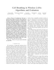
Fig. I The overall schema <strong>of</strong> <strong>the</strong> experiment. The experiment has two parts: initialization,<br />
represented by I,l-oken Irnes, and <strong>the</strong> lookup <strong>of</strong> surface orientattons for a given object uslng<br />
mearui.ec1 image brightness. Brightness arrays obtained from a TV camera are notmallzed<br />
A looLr~p table is constructed in <strong>the</strong> initial process using reflectance map techniques and<br />
Nw~on's method. The table is used to obtain surface orientations.<br />
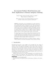
Fit;. ? Nrcclle diagram showing (projected) surface normals on <strong>the</strong> surface <strong>of</strong> a nrctalhc<br />
splie~e. Each needle shown st~ck~ng up out <strong>of</strong> a point represents <strong>the</strong> orientation <strong>of</strong> a surface<br />
I<br />
.-.
Ikellchi Fc Horn Photornett ic <strong>Stereo</strong><br />
Thc geomrrrrc dependence <strong>of</strong> <strong>the</strong> reflectance characterrstics <strong>of</strong> a sui face can be expi ~qwd tn<br />
tel ms <strong>of</strong> <strong>the</strong> drlection from <strong>the</strong> surface to <strong>the</strong> vlewer, <strong>the</strong> d~rectron ftom <strong>the</strong> surface to [he<br />
Irg ht-source and <strong>the</strong> sui face normal. The apparent brightness (scene radtance) seen by <strong>the</strong><br />
vrewet can be expressed as a funct~on <strong>of</strong> <strong>the</strong> three angles between <strong>the</strong>se direcmrss<br />
Altetnattvely, we can express <strong>the</strong> dependence in terms <strong>of</strong> <strong>the</strong> slope components p and q.<br />
used as axes in gradient space Ell. There are several ways to project <strong>the</strong> unlt surface normal<br />
onto a plane. In <strong>the</strong> "traditional" method one projects a point on <strong>the</strong> unit sphere onto a<br />
tangent plane from a center placed at one pole <strong>of</strong> <strong>the</strong> unit sphere. The plane is tangent to<br />
<strong>the</strong> sphere at <strong>the</strong> opposite pole (stereo-graphic projection). This projection may bc us~fitl<br />
wher~ we consrder characterist~cs <strong>of</strong> a surface which has both specular~ty and tianspareiq<br />
l~he <strong>the</strong> sutface between air and water or wmdows <strong>of</strong> <strong>the</strong> John Hancock hir~lding,, one<br />
hem~sphere corresponds to reflected brightness distribution, <strong>the</strong> o<strong>the</strong>r to transmttted<br />
brightness distribut~on.<br />
t%'hete z=Z(x,y) and <strong>the</strong> slgn is chosen dependrng on whe<strong>the</strong>r <strong>the</strong> pow 1s nn <strong>the</strong> ti(~\.va~d<br />
hrm~si~l~ete ot <strong>the</strong> downward tiemlsphere. In ano<strong>the</strong>r method, wh6ch has been ~scil by<br />
1 lot n [I], one p~ojects <strong>the</strong> unit surface normal onto <strong>the</strong> tangent plane from <strong>the</strong> cmro <strong>of</strong> t h ~<br />
unit sphere (central projectton).<br />
p = ~'+L/.'+x<br />
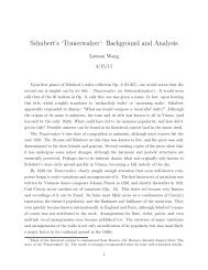
(a) Tile stereogt aph~c projection. b) Hot n'~ projectton. Note rts s~rnplicq<br />
Fig 3 Noln's projection and <strong>the</strong> stereographic projection onto a plane.<br />
Altliougli <strong>the</strong> ttaditlonal method may be more farnii~ar and allows one to express any
Ikctrchr #? Horn 5 <strong>Photometric</strong> <strong>Stereo</strong><br />
drtcctioii wrthout ambrgutty, <strong>the</strong> zen~th angle is projected into half <strong>of</strong> <strong>the</strong> zenlth an;lc and.<br />
~IIIIS, <strong>the</strong> coo~drnate t~ansformatm 1s not as convenient as tt is for <strong>the</strong> second mrtliod<br />
hloi~over, we only need to consider <strong>the</strong> upper hemisphere <strong>of</strong> possible drlections, srnce<br />
surfaces tutn~ci away flom <strong>the</strong> viewer cannot be seen in any case It is foi <strong>the</strong>se teasons<br />
that we have chosen <strong>the</strong> gradient space projection<br />
If we take <strong>the</strong> di~,ection from <strong>the</strong> surface to <strong>the</strong> viewer as <strong>the</strong> direction <strong>of</strong> <strong>the</strong> z-a'xis, <strong>the</strong>n<br />
<strong>the</strong> i.eflectance propei.ties <strong>of</strong> a surface patch depend on (p,q), <strong>the</strong> direction <strong>of</strong> <strong>the</strong> surface<br />
riot.rnal arid (p,,q,), <strong>the</strong> direction to <strong>the</strong> source [il. Each point in gradient space (<strong>the</strong> tangent<br />
plnne), corresponds to a particular surface orientation (based on <strong>the</strong> direction <strong>of</strong> <strong>the</strong> v~rwer).<br />
If we know <strong>the</strong> r.cflectance characteristics <strong>of</strong> an object, we can calculate how bright a surface<br />
elcmcnt with that orientation will appear. It is convenient to use contour lines to connect<br />
those points in gradient space which correspond to surface orientations which give rise to<br />
tho sanw apparent brighrness. It is because <strong>of</strong> <strong>the</strong>se contour lines that <strong>the</strong> resulting d~agram<br />
is ~.cfri.twd to as <strong>the</strong> "reflectance map" [I]. It is 'denoted by R( p,q ).<br />
Ihirig <strong>the</strong> i~rflectance map, <strong>the</strong> basic imaging equation is<br />
E,(s,y) .= R,( p,q,x,y ), (3)<br />
whet.e E,(x,y) is <strong>the</strong> brightness (image irradiance) in <strong>the</strong> image-forming system at <strong>the</strong> point<br />
(s,y) in <strong>the</strong> image plane. This equation contains two unknown variables p, q atid one<br />
qua~itity E,. which can be measured in <strong>the</strong> image.<br />
In <strong>the</strong> above equation, <strong>the</strong> subscript j is used to denote different illumination condrtions.<br />
For each value <strong>of</strong> <strong>the</strong> subscript, a different image is obtained, and a different reflectance<br />
map al~plres. If two images are taken, two such equations provide constraints on <strong>the</strong><br />
[~ossrhle values <strong>of</strong> p and q. This permlts us to solve for <strong>the</strong> gradient. Because <strong>of</strong> tlw non-<br />
lin~arity <strong>of</strong> tile equations, however, a number <strong>of</strong> solutions may be found at times. In this<br />
case, a thrtd Image may he used to disambiguate <strong>the</strong> remaining possibilrties. This is <strong>the</strong><br />
principle <strong>of</strong> photomett.ic stereo [2,3,1.<br />
*<br />
Ot tllogt apliic ptojectron can smplify <strong>the</strong> calculatron considerably. If we can assume that<br />
tli~ chjrct is small compared w~th <strong>the</strong> distance to <strong>the</strong> source and <strong>the</strong> image-forming system,<br />
thrn <strong>the</strong> vrewet d~iectron can be approximated as <strong>the</strong> axis <strong>of</strong> <strong>the</strong> image-fotn~rng systm, and<br />
wt can tieat <strong>the</strong> system as orthog~aph~c There are two rneztts to this approxlmatrotl One<br />
IS that we can n~glect <strong>the</strong> effect <strong>of</strong> posrtron The right hand s!de <strong>of</strong> Eq 3 depends only on<br />
(11.q)~ namely. we can apply <strong>the</strong> same reflectance map on all polnt in <strong>the</strong> Image <strong>An</strong>o<strong>the</strong>r<br />
I)~nriit is that we can calculate R( p,q ) more easily because <strong>the</strong> approximation frkes <strong>the</strong><br />
viewing ditectfon So we can, far example, rotate <strong>the</strong> source keeprng <strong>the</strong> phase angle
lkeuctii & Horn 6 P hatmwtric <strong>Stereo</strong><br />
constant (Thc phase angle is <strong>the</strong> angle between <strong>the</strong> soulce and <strong>the</strong> vww, rneasul ed a: thc<br />
object). This means that we can obtam a new reflectance map just by rot-acrng <strong>the</strong> old o.is<br />
[31<br />
2 Basic Consideration<br />
2.1 Relationsltip betweeii Radiance aid Irradiance<br />
One <strong>of</strong> <strong>the</strong> main po~nts <strong>of</strong> our d~scussion here IS that we consider only specular components<br />
<strong>of</strong> I eflectance when we calculate <strong>the</strong> reflectance map, srnce many indust1 ial matel gals ate<br />
nvde <strong>of</strong> metal and have strong specularity and little drffuse reflection Experrmerlts show<br />
that only 1 or 2% <strong>of</strong> <strong>the</strong> incident light is reflected diffusely from some metallic siitfacrs, w~th<br />
17-10st <strong>of</strong> <strong>the</strong> rest reflected specularly. We cannot treat this kind <strong>of</strong> material using thr iisua!<br />
Larnl~er tian rnodel fot reflection <strong>of</strong> I~ght f~orn a surface It is also cleatly InappIopr late to<br />
use poltit soutces to ~llumrnate such a surface, since very few surface patches wtll be or rented<br />
COI I rctly to reflect any light and we w~ll only see virteral rn-rages <strong>of</strong> <strong>the</strong> pornt sources<br />
\Ye co~ls~det two kinds <strong>of</strong> ilght sources One 1s an extended Itght source The o<strong>the</strong>t 1s a<br />
colltmated one. <strong>An</strong> example <strong>of</strong> an extended lrght source is a fluorescent 11ght flxtuie A<br />
coliirnarrd 11ght may be generated by using a laser and an inverted telescope<br />
Th: PP I ciationships exist between a light source and <strong>the</strong> image plane The frtst one rc that<br />
betwcen sotrlce radiance and incident ~rradaance on a sample surface Next, and most<br />
lrnpot tant, is that between mctdent nrradlance and ernnttmg radiance from <strong>the</strong> surface (th~s<br />
1s capttited SII <strong>the</strong> reflectance map). The last one is that between emittang radiartce and<br />
Image ~rtadiance. S~nce <strong>the</strong> two kitids <strong>of</strong> itght sources have somewhat different<br />
I elatioriships, we cons~der <strong>the</strong>m separately.<br />
(extended source)<br />
T ~ telatronship P<br />
between source radiance from an extended l~pkt and <strong>the</strong> rncidmt<br />
in iidiance ,s fa~rly straightforward. We assume a surface patch <strong>of</strong> a Ilght source ('CIA) rs<br />
emttrliig enetgy to a rut face patch <strong>of</strong> a sample surface (dB). The emitted energy from <strong>the</strong><br />
soirlce i11cdent on <strong>the</strong> sample surface ns<br />
dF, = L,do,dAcosO, ( 4 )<br />
= ~,(1/r~)d~d~cosO,cos0,.<br />
wheto o, IS a solid angle correspondmg to <strong>the</strong> surface patch dB vrcwed from dA, and I- is<br />
tlw d~stance between <strong>the</strong> source and <strong>the</strong> sample surface. On <strong>the</strong> o<strong>the</strong>r hand, <strong>the</strong> received<br />
flux IS
A@-'%<br />
Ikeuchi Pc Horn <strong>Photometric</strong> <strong>Stereo</strong><br />
Radiance '<br />
L i Emitting<br />
ihidcnt! Rndinnce<br />
Fig. 4 Relationshrps between light source, surface, and image plane are depicted.<br />
dF, = Lld~sdB~~~Os ( 5<br />
= ~,(l/r~)d~d~cos~,cos@,,<br />
whete w, IS a 50hd angle correspond~ng to <strong>the</strong> surface dA <strong>of</strong> <strong>the</strong> source vrewed from dB.<br />
If L, and L, can be regarded as constant within <strong>the</strong> small areas dA, dB, <strong>the</strong>n<br />
L, = L,. ( 6 )<br />
This rniplies that we can regard <strong>the</strong> "rncident radrance" as <strong>the</strong> source radiance In <strong>the</strong> same<br />
For a specular sill face and an extended source, we can obtain from <strong>the</strong> defrnltron <strong>of</strong> <strong>the</strong> bl-<br />
clitcctronal reflectance distrrhution function (BRDF) [1,4]<br />
whet e<br />
L,(O,.+,) = Uf,,, dE,<br />
= JJZ~(SI~~~,-S~~~,) a(+,-9,cn) L1(O,,O1)cosOlsinO,dQ, d9,<br />
= L,(@,,+,+n), (7)<br />
f, , = 26(srn20,-s~n~0,)6(4,-+,+n) (8)<br />
1s <strong>the</strong> RRDF fat a perfectly specular surface; L,(O,,+,+n) is <strong>the</strong> "mident radiance". and<br />
L,(O,,J.,) is <strong>the</strong> reflected radiance. Thrs result is also predrcted from elementary physrcal<br />
laws Thus, even though <strong>the</strong> source drstrrbution may be complrcated, only <strong>the</strong> conttrbutlon<br />
fmm a srngle d~rection (@,,4,+tr) need be considered and one need not be concerned with<br />
<strong>the</strong> effects <strong>of</strong> o<strong>the</strong>r areas <strong>of</strong> <strong>the</strong> distr~buted lrght source Strictly speaking, L, is not defrned
Ikeuchr 8c Horn 8 Photnrnetr~c <strong>Stereo</strong><br />
as a funct~on <strong>of</strong> local angles but vlewer angles. Light source w h ~ h we can consrtuct has a<br />
f~xecl brlghtness dtstrrbution on <strong>the</strong> viewer system. However, it 1s easier te understand <strong>the</strong><br />
result expressed uslng <strong>the</strong> above notation. In <strong>the</strong> next sectton we will gave <strong>the</strong> Equations I w<br />
<strong>the</strong> transfot matron between <strong>the</strong> vrewer coordinate system and <strong>the</strong> local coordinate sy stcm<br />
The relatronshrp between reflected (scene) radmce and image irradrance 1s<br />
E, - {~ni4)(d1f,)~cos~nj~~, (9)<br />
whw e fp. d, cr are effect~ve focal length <strong>of</strong> <strong>the</strong> lens, <strong>the</strong> diameter <strong>of</strong> <strong>the</strong> entrance apt tut e<br />
and <strong>the</strong> <strong>of</strong>f-3x1s angle, respectively[ 2 I.<br />
Fln~lly, uswig on Eq 6,7,9 we see that rrnage irradrance at a particirlar point 1s prop, tional<br />
to <strong>the</strong> source rad~ance in a drrect~on which depends on <strong>the</strong> orlentatron <strong>of</strong> <strong>the</strong> cot req~ond~ng<br />
su~ face patch[ 1 I. That IS, <strong>the</strong> brrghtness <strong>of</strong> a partnezlaa surface patch is simply equal to <strong>the</strong><br />
b~ rglitness <strong>of</strong> <strong>the</strong> part <strong>of</strong> <strong>the</strong> extended source which it happens to reflect. Thr!s, even<br />
though <strong>the</strong> source drstribution may be complrcated,<br />
d~rrt.tron Ip,.q,) need be considered at any tlme.<br />
(cralli~~iated light source)<br />
In <strong>the</strong> case <strong>of</strong> a collrmated source, it is easy to use<br />
only <strong>the</strong> contrthutinn from a crnglo<br />
irradiance to measure wla'l~orlsh~p<br />
hrt~~erii source ItitPnstty and mcrdent brightness Clearly, provided that a surface patch IS<br />
small compared to <strong>the</strong> d~arneter <strong>of</strong> <strong>the</strong> source, source irrad~ance E, ts <strong>the</strong> samp as El<br />
nwasuled on a surface lying orthogonal to <strong>the</strong> rays. According to [ t I, ~ncldent racl~ance k,<br />
IS<br />
L,(O,,Q1,j E$(0,-0,)6(+,-+,)Is1n6,. ( 10 )<br />
Thp beauty <strong>of</strong> thrs expresston rs that <strong>the</strong> double-delta expressjon has dimension<br />
[ Ilst~~taci~at~ I because when rt rs mtegrated with respect to sold angle <strong>the</strong> result has no<br />
d~rnrns~on So <strong>the</strong> total dimenston <strong>of</strong> <strong>the</strong> rrght hand side <strong>of</strong> Eg 10 is [ wattl(rn2sr) I and rt<br />
cottryonds to <strong>the</strong> left hand s~de. If all <strong>the</strong> dl~ectmn are covered with coll~n~ated soutces<br />
each <strong>of</strong> which has a particular brlghtness distmgurshed wtth <strong>the</strong> drreceiora,<br />
IJG ,, 11,) = c~E,~G(o, -@,k)~(lp,-+,k)l~~~@,, ( 11 )<br />
wlie~r k ci~noles <strong>the</strong> k-th irght source.<br />
Now WP c2n calculate <strong>the</strong> scene radrance by using <strong>the</strong> BRDIFe 1,4 I The BRDF for <strong>the</strong><br />
su~face IS <strong>the</strong> same as In <strong>the</strong> former case and rs glven rn Eq. 8<br />
- L,(@,,+,+n)<br />
Agaan, <strong>the</strong> same abbreviat~on<br />
L,(O,,dl,) = JSL, (0,,$,)26(sin20,-~1&,)6(~,-4,+n)cos@,s1n@,d~,d~, f 12 )<br />
1s used; namely, brightness dfstrtbutstsn E.,k IS not clcfmed as<br />
A
lket~ctii Pc Horn 9 <strong>Photometric</strong> <strong>Stereo</strong><br />
a functron <strong>of</strong> <strong>the</strong> local coordinates, This will be discussed in <strong>the</strong> next sectron.<br />
The relat~onsh~p <strong>of</strong> scene radiance and image irradrance is, <strong>of</strong> course, <strong>the</strong> same as for <strong>the</strong>,<br />
extended ltght source In thrs case rue also f~nd that, uslng Eqs 11, 12, 8, <strong>the</strong> image<br />
trvadia nce can be calculated from <strong>the</strong> sor~rce irradrance determrned by <strong>the</strong> or lent ation <strong>of</strong> <strong>the</strong><br />
local not ma1 on <strong>the</strong> surface patch.<br />
(transfori~~ation f ronl a local coordirlate syste111 to a viewer coordit~ate systelii)<br />
It 1s convenient to change from <strong>the</strong> local coordinate system to <strong>the</strong> vrewer-centered coordrnate<br />
system [I] because <strong>the</strong> reflectance map is defined in a vrewer-centered coordrnate syst~rn, and<br />
<strong>the</strong> light soutce d~sttibutron 1s given based on <strong>the</strong> drrectron <strong>of</strong> <strong>the</strong> vrewer.<br />
111 both cases, we have to determ~ne <strong>the</strong> viewer coordinates correspondmg to (@,,+,+n)<br />
when <strong>the</strong> vlewer and <strong>the</strong> surface normal have <strong>the</strong> relat~onsh~p spec~fied by (@,,Q.,). By<br />
using <strong>the</strong> telatiotis<br />
0, = 0, = en,<br />
+, = +, + 7r, ( 13 )<br />
we get <strong>the</strong> cot responding directions <strong>of</strong> <strong>the</strong> vlewer coordinate<br />
8, = Zen<br />
4, 4" ( 14 )<br />
This reiat~onsh~p 1s obta~ned er<strong>the</strong>r by cons~derrng Fig. 5 or subst~tuting Eq. 13 into<br />
splie~ ~cal tl igononietrrc relatrons<br />
Thus, we can rewl lte Eq 7 and Eq. 12 using <strong>the</strong> viewer-center coordinate system<br />
E,(8,,6,) = nLfOn.~,) = aL@@,,$,),<br />
whete cr IS a constant. We observe this Ep as image irradtance.<br />
Fi om Eq. 14 we can also obtain<br />
ps = 2 11" 1<br />
qs = 2 qn 1 (1-Pn2-qn2).<br />
( 15.1 )<br />
We can f~nally express brightness drstrrbutron In <strong>the</strong> gradlent space. In <strong>the</strong> case <strong>of</strong> an<br />
extenclcd hght sotrrce, <strong>the</strong>re is no problem.<br />
W ~ P I<br />
R(pn,q,) = Ls(t)s,qs)t<br />
e<br />
11, = &/ax = -cosQt,tan%,<br />
q, = 3z13y = -sln$,tan8,.<br />
( 16.1 )
Ikeuchi k Horn 10 <strong>Photometric</strong> <strong>Stereo</strong><br />
-- -- 2<br />
- -- - -<br />
Flp 5 Relat~onships between a local coordinate system and a viewer coordmate system.
Li<br />
Plh<br />
Ikeuch~ IG Horn 11 <strong>Photometric</strong> <strong>Stereo</strong><br />
2.2 C:onsirleratio~t on Types <strong>of</strong> Brightness Distribution,<br />
2 2<br />
The map(?lng ~p,.q,)~U={(x,y)Iix ty )
Ikeuchi & Horn PPknZonwtric <strong>Stereo</strong><br />
3 <strong>Application</strong> Problems<br />
3.1 Total Srtaema <strong>of</strong> <strong>the</strong> System<br />
Table 1<br />
The techniqite lequlres two kinds <strong>of</strong> tasks; one IS <strong>the</strong> <strong>of</strong>f-he (pre-comput~ng) job and <strong>the</strong><br />
o<strong>the</strong>l 1s <strong>the</strong> on-lme (real-t~nie) job wh~ch is ra<strong>the</strong>r s~rnple compared wlth <strong>the</strong> <strong>of</strong>f-hnr job<br />
Tlw slmpl~c~ty ~nipl~es rap~d calculation, as dewed in any hand-eye system The <strong>of</strong>f-iinc<br />
job conslsts <strong>of</strong> niak~ng <strong>the</strong> reflectance map and consrructtng a lookup table The on 111tr job<br />
conslsrs <strong>of</strong> readlng <strong>the</strong> Image br~ghtness and determm~ng orlentatlons <strong>of</strong> a surface patch<br />
basrcl on <strong>the</strong> lookup table. Flg. 6 shows <strong>the</strong> informatton flow between <strong>the</strong> on-ltne job and<br />
<strong>the</strong> <strong>of</strong>f-hne job.
~"9<br />
Ikeucht Ir Horn 13 <strong>Photometric</strong> <strong>Stereo</strong><br />
-- - -- - -- -- -- - - - -. - -<br />
Fig 6 The ovelall schema <strong>of</strong> <strong>the</strong> experiment The technique consists <strong>of</strong> two types <strong>of</strong> jobs:<br />
<strong>of</strong>f-l~ne plepalatroll <strong>of</strong> tables (represented by broken lines) and on-lrne processrng. image<br />
blrghtness 1s obta~ned by using a TV camera. We search for <strong>the</strong> maximum value <strong>of</strong><br />
bltghtnesr in each alray. Br~ghtness arrays are caltbrated and normallzed. Surface<br />
orlentations are obtarned from <strong>the</strong> lookup table.<br />
3.P Cotlrideratint~ <strong>of</strong> Light Source<br />
We uw a Lambel tlan surface as a source plane, It is ~lluminated by a h ear tamp as shown<br />
in F I 7 ~ Though a spher~cal shaped source can easily cover dtrections <strong>of</strong> mote than nrnety<br />
drglw, it IS d~ffrcult to build such a devlce and dlfflcult to control <strong>the</strong> d~strrhut~ori <strong>of</strong> <strong>the</strong><br />
l~glit on tt, paltic~rlally if rnterflectron are taken into account. On <strong>the</strong> o<strong>the</strong>r hand, II we use<br />
a pianal souice lllumlnated by a lamp, <strong>the</strong> brightness dtstrtbutlon IS complicated, but we<br />
can calculate a reflectance map as in case 2 <strong>of</strong> Table I. It is poss~bte to cover angles <strong>of</strong> more<br />
than nrnety degtws by makrng a box-like source. In that case, however, we have to treat<br />
each plane separately because <strong>the</strong> surface normal 1s not differentrable at <strong>the</strong> mtersectton <strong>of</strong><br />
two pIa~?es Thus, we cons~der one plane surface which is assumed to have <strong>the</strong> Lambel tian<br />
chalactelisttcs in older to obtatn kome analytlc resutts to help In <strong>the</strong> design <strong>of</strong> <strong>the</strong> system.<br />
Thls plane IS ~lluminated by a tine source as a representative case.<br />
BI ~ghtness d~str~~button on <strong>the</strong> surface is calculated using Eq. 18. Let f be <strong>the</strong> flux I ate per<br />
unlt source length [ watt/(m sr)]. Then <strong>the</strong> total irradiance E wattlmZ 1 is<br />
E = $fcos~~cos@~/r~dt. f 17 )<br />
2 2 .<br />
F~om cosP, = Jx +lo /I and ~ 0 5 % = lolr, ~ we can finally get<br />
E = (flo/2a2)[{tan-'(y+~)la - tan-'(y-l)la]<br />
+( a(y+~)/(aZ+(y+~)2)-a(y-~)l(a2+(y-~)2) 1 1, ( 18 1
Ikeuch~ & Horn <strong>Photometric</strong> <strong>Stereo</strong><br />
TV-CAMERA<br />
&Y OBJECT<br />
2<br />
r2=x2+(y-t) +LO I<br />
THE LAMBERTIAN<br />
SURFACE<br />
(REAL LIGHT SOURCE)<br />
FIR 7 The object IS ~llum~nated solely by <strong>the</strong> hght reflected <strong>of</strong> an overhead Larnbert~an<br />
sulface Th~s surface recelves lrght from a linear lamp pos~t~oned below so as not to<br />
~llilrnrnate <strong>the</strong> object The TV camera peers through a small hole In <strong>the</strong> overhead surface.<br />
Blrghtness d~sttibut~on f~om a linear lamp on <strong>the</strong> Lanibert~an surface can be calculated In<br />
Eq 18 We used three llnear lamps, placed symmetr~cally, 120 degree In <strong>the</strong> center <strong>of</strong> <strong>the</strong><br />
lamps <strong>the</strong>re I$ a hole The object 1s observed through <strong>the</strong> hole.
Ikerrchi #? Horn<br />
<strong>Photometric</strong> <strong>Stereo</strong><br />
ivhete a = m, L 1s <strong>the</strong> length <strong>of</strong> th e line source, and lo i 's <strong>the</strong> dista nce between <strong>the</strong> line<br />
source and <strong>the</strong> Lambertian surface.<br />
M1e put an object just under <strong>the</strong> point (x,y) = (0.510,0.0). E(x,y) is a symmetric function w~th<br />
respect to y. Thus; it is natural to put an object somewhere on <strong>the</strong> x axis. E(x,O) is an s-<br />
shape function and has a inflection point near x=0.5Io. At that point<br />
E(0.51,,0.0)=0.715E(000tOOO), So it is convenient to put an object just under this point. If we<br />
denote <strong>the</strong> distance from ttie surface to <strong>the</strong> object as 11,<br />
x = -l,ps+Io/2<br />
Y = -11%<br />
Frnally, we can get a reflectance map<br />
tan- ' ((-I lq,+lo/2)/ A-I ps+1012)2+102~-tan-i ((-1 1qr-lo12)~J-l Ips+lo12)2+lo21<br />
2 2<br />
( 19 )<br />
+[ .,A-1, ps+lo/2)Z+lo4-1 lqS+~o/2)~~{(-~, pp+l0/2) +I0 4-1 lqf+10/2)2)<br />
2 2<br />
-{,A4 ps+lo12~z+lo~~-l lq~-~o/2~l/~~-l,ps+lo/2~<br />
+lo +(-1,~~-1~/2)~~1, ( 20 )<br />
where p, and q, are as defined above, and L = I0,2l1 = lo because <strong>the</strong>se values are fowd to<br />
be optimal upon s~mulat~on.<br />
M'e IISPCI thlee I~near lamps, placed symmetrically, 120' apart, about <strong>the</strong> hole through which<br />
<strong>the</strong> objrct IS ohsetved. One lamp is turned on at a time, glvlng rlse to a reflectanct map<br />
like <strong>the</strong> one shown in Eq 20.<br />
6v rrsrng ti11 PP refl~ctance maps, we can deternme <strong>the</strong> surface orlentatton. Theoretically it<br />
is l-~os~rbl~ to d~te~nilnc <strong>the</strong> orlentation by uslng two maps only. However, <strong>the</strong>re may be<br />
nioif than one solutron because <strong>of</strong> <strong>the</strong> non-linearity <strong>of</strong> <strong>the</strong> equations. If we use three maps,<br />
WP can Cf~tmniilie a unque solutron eastly as shown in Fig. 8.<br />
3.3 ilnw to Makc a Lookup Table<br />
The most convenient method for converting a triple <strong>of</strong> measured brightness to an<br />
orie~itation is by means <strong>of</strong> a lookup table made from <strong>the</strong> reflectance maps. This table.<br />
iticl~xed by quantized brightness measurements, contains surface orientation. Although ~t is<br />
possible to make a three dimensional lookup table in which each dimension corresponds to<br />
<strong>the</strong> brrgtitness <strong>of</strong> a surface patch under one <strong>of</strong> <strong>the</strong> three sources, <strong>the</strong> weakest brightness<br />
contalns relatively large measurement errors and we use it only to choose a solution betweeri<br />
two alternatives. Thus, <strong>the</strong> lookup table can be two dimensional. we look up an entry<br />
using <strong>the</strong> two largest brightness values. Each entry contains two alternative solutions. Each
gradient space Since <strong>the</strong> lamps are symmetrically configured, brightness disrr~bi~tion<br />
cor~.espond~ng to a linear lamp is also symmetric havlng <strong>the</strong> same shape. Thus, we need to<br />
calculate oniy one distribution and <strong>the</strong>n rotate it 120 degrees. The resulting fonct~on is <strong>the</strong><br />
drsrrcd one.<br />
We can cieternl~ne (p,q) from three values <strong>of</strong> brightness, where each br~ghtness value<br />
co~~~~rsponds to each source condition. For example, switching on source I will yield a<br />
br~ght~ie~s value <strong>of</strong> 07822 at cell B S~milarly, source 2 and source 3 yield 0.5829 and 0.9150,<br />
rrsp~ct~vely<br />
From <strong>the</strong> above d~agram,<br />
we note that <strong>the</strong> point ( -0.'1 -04 ) satisf~es<br />
this triple.<br />
Hence. <strong>the</strong> \lirface orientation at <strong>the</strong> cell A is ( -0.1 -0.4 ).
Ikeuchi cPc Horn<br />
alternat~ve solut~on also contains a surface orientaeion and <strong>the</strong> thtrd brightness<br />
We construct <strong>the</strong> lookup table by using Newton's method. <strong>An</strong> elegant method exists <strong>the</strong><br />
case <strong>of</strong> a Lambert~an reflector and point sources 12). In our case, however, we have to<br />
calctrlate it nirmerically. Specif~cally, we solve two expressions Itke Eq. 20 for p and q The<br />
expressions d~ffer in <strong>the</strong> brightness distrrbution <strong>of</strong> <strong>the</strong> source, obtained by turnlng on one <strong>of</strong><br />
<strong>the</strong> three hear lamps<br />
Tlie~e are two chorces for <strong>the</strong> calculat~on One method, whsch we rejected, dlvrdcs <strong>the</strong><br />
gradlent space Into a mesh and gets a solut~on by interpolat~on. A s~mtlar tcchnlqiw IS<br />
conrldeted in [ 6 I to make an exact color from a combination <strong>of</strong> three prrmal colo9s T hey<br />
ttrcd to flnd <strong>the</strong> nearest grid pornt to a solution and <strong>the</strong>n determine wh~ch ne~ghbsr~ng !9or<br />
(<strong>the</strong> snlall space between grid polnts) contarns <strong>the</strong> solution. F~naHy, <strong>the</strong>y used an<br />
infetpolat~on method from vertrces <strong>of</strong> <strong>the</strong> box to defermine <strong>the</strong> r~sult. The technfqoe wotrld<br />
be useful when a reflectance map is obtained exper~rnentally.<br />
Thr o<strong>the</strong>r niethod is to solve Eq 20 numer~cally for p and q. 4n case that reflectance maps<br />
alc glvm In analyt~c form, rt makes sense to use Newton's method. Moreover, we have<br />
fol~nd that Newton's method converges within four iterations wtth r~latlve error smaller<br />
than C1001, gtovtded that <strong>the</strong> ln~t~al polnt 1s well chosen. Smce th~ nelghbor~ng solrntioris <strong>of</strong><br />
thr lookup table ale good mtlal pomts, <strong>the</strong> calculation requires <strong>the</strong> order <strong>of</strong> 4~', whcre N<br />
is <strong>the</strong> rturnhe~ <strong>of</strong> mesh points, whrle <strong>the</strong> former method needs at lease ~ ~ caiculdtrons 1 2<br />
bew3es <strong>the</strong> tnrtial calculattons at each mesh.<br />
Tire N-d~mensronal Newton method involves solving <strong>the</strong> simultaneous linear equations:<br />
f,+Zi, . I"df,ldxklxk , x,b!xk[~+'l-xki'~) = 0, ( 21 )<br />
wheie f, ts <strong>the</strong> r-th element <strong>of</strong> a vector functlon <strong>of</strong> n dimensions and x,lif is <strong>the</strong> i-rh ci~l-nerpt<br />
ui a soluc~on vector <strong>of</strong> <strong>the</strong> J-th iteration.<br />
F~nn, <strong>the</strong> cons~deratton <strong>of</strong> Sect~on 22, we can treat <strong>the</strong> reflectance map as a functtorr <strong>of</strong><br />
(pq.qs) 1, hen we get a solut~on using Newton's method. Newton's method frnds an<br />
rnrrl rrctms <strong>of</strong> two surfaces. Smce Eq. 20 1s drfferentiabie, <strong>the</strong> result is a regular silt face<br />
and <strong>the</strong> I~PI ation COISVPI ges to a parnt along <strong>the</strong> regular surface. From <strong>the</strong> corisrdcr;ri~on sn<br />
Append~x and Sectlon 22, this situation caw be observed from ei<strong>the</strong>r <strong>of</strong> two<br />
paranietetizat~ons and <strong>the</strong> expression <strong>of</strong> <strong>the</strong> result In one parameterrzation should<br />
cortq3ond to <strong>the</strong> o<strong>the</strong>r exactly. Thus, we use a function parameterszed by (p,,g,) ?s f, we<br />
obra in a numer~cal solut~on and <strong>the</strong>n we project <strong>the</strong> solution to (p,,q,) space.<br />
-
Ptlotoniet~ IC <strong>Stereo</strong><br />
IVt can ~ewr lie Eq 21 as Eq. 23. in our case <strong>of</strong> a planar source iliuminated by a I~near lamp.<br />
The two nnliplng functrons are<br />
f(llsqq,) - R(p5,qs)-E,,,<br />
K(ps.qg) = R(l~s~~s~~-qs~rnu,pS~in~+qScosa)-Ep,m, ( ?2 )<br />
B~IIPIC rt IS all angle between two lrght sources and E,,", E,,, are image brr~~l~tr~css<br />
cot I cy~onrllng to <strong>the</strong> (n,m) element <strong>of</strong> <strong>the</strong> lookup table. We can finally get<br />
S[I" 1 = [I]-(F')"F, I 23 )<br />
wlirtc S = '(j~,.q,), F = '(fqg) and (F')~' is a inverse <strong>of</strong> <strong>the</strong> Jaccob~an matrix.<br />
.Jlw con,[,lcte ale;o~.rthni is shown ill Fig. 9 At first, we try to fmd solution co~.rezpor~tirng to<br />
a I~rightnr$s pair (0.4.0.4) from initial points (1.0,i.O) and (-1.0,l.O). Next, we procseci to gct<br />
soli~rrons along a line on which <strong>the</strong> first brightness is constant (0.4), using furmcr roi~ltrori,~<br />
as nrvi ~nitial points until two corresponding solutions from two different dir,ect~ons are thc<br />
same nt, we cannot get solirtions within five iterations. Then, we go to <strong>the</strong> next mcsh point<br />
alnng a liue on which <strong>the</strong> second brightness is constant (0.4). After <strong>the</strong> entirr arca is<br />
p~'c~cewti, <strong>the</strong> algorithm terminates.<br />
Fig. 9 How to get entire solut~ons using Newton's method.<br />
-<br />
-- - - - -<br />
. .
Ikeuchi R. Horn<br />
3.3 iiow to Cpt a Surface Orie~itatiw<br />
Image httghtness IS obtained from <strong>the</strong> TV camera. To reduce <strong>the</strong> now tyl)ical (11 r b c<br />
deviccs, we took more than one picture per llght source, and arrays cotrespc~ncir~rt ict I he<br />
salve Ir~ht soulce weie averaged. The resulting three br~ghtness arrays, one for raci~ l~ght<br />
sut~~ce, wete <strong>the</strong> input to <strong>the</strong> photomett ic stereo system.<br />
Mlr watch each allay for tts niaxlmuni brtghtness. If objects are convex and thc vi.rtr;ll<br />
thp lna xrm~rm sortlce b~ lghtness. By norrnal~zrng <strong>the</strong> results using thcse maxtmurn val~rrs,<br />
WP ran cancd <strong>the</strong> effect <strong>of</strong> varying albedo and Image sensor response. Naniels, l.c.f. can<br />
idetitify <strong>the</strong> maxrnitrm value In an Image array with <strong>the</strong> value I0 rn <strong>the</strong> rcllrctancc 113;lp<br />
HOWVPI, we cannot normalrze <strong>the</strong> values <strong>of</strong> <strong>the</strong> image arrays at th~s stage hecausr <strong>of</strong> <strong>the</strong><br />
rton-lruparity <strong>of</strong> <strong>the</strong> TV camera. Nornnltzat~on will be done after <strong>the</strong> value 4s c;rl~l)~ atccl<br />
111 o<strong>the</strong>r wold, since <strong>the</strong> ourput <strong>of</strong> <strong>the</strong> TV camera 1s not linearly proporr~onsl to a<br />
I~ri~.titness valrre, we have to normalize <strong>the</strong> output after we convett <strong>the</strong> o~rtput to a crttain<br />
valu~ ~~opott~onal to mage brightness. It IS Interesting that <strong>the</strong> maxtntum point always<br />
cori ta rns Intportant information arid thrs search resembles Land's hg ht~iess search model<br />
[ 7 I<br />
I:t r~lttricsq caltbratton 1s done using a six step KODAIC gray scale. No~ntalrzatlon I< bnr6.d<br />
on thr nlaxrn,um value So each point on <strong>the</strong> Image has a rr lple <strong>of</strong> calib~ateci ijt I ,htt~esc<br />
~~t~dcl thlec. cl~ffetcnt llght sources<br />
rir11n tlw lookup table we can get <strong>the</strong> strrface orrentatton. The lookirp tablc rlttty<br />
accewd IIWF <strong>the</strong> two la~gest bl lghtness values The looki~p table IS actually two tt i;111) \ r l ~ t<br />
ILIYI tl~mensrona 1 matt Ices To Increase <strong>the</strong> accuracy <strong>of</strong> computation atid eco~~oi~iy o! riir~rm y<br />
itw, <strong>the</strong> ft~st d~nwrsion represents <strong>the</strong> latgest lmage br~ghtness The spcatid clr~~trnsr~n<br />
rri)twwts to <strong>the</strong> second largest Each element <strong>of</strong> <strong>the</strong> matrix contatns <strong>the</strong> corl~rj~ottrlrlre<br />
sul far^ ot ~Pntat~on and <strong>the</strong> smallest Image brightness<br />
Sinw ttic ncirr-lrn~a~ ity gtves I lse to two solut~ons for each intensity pats, we havc (i+ I lr!r*<br />
wlirrl~ one IS <strong>the</strong> real one We choose a surface orientation by comparing thc ctlc'attcc<br />
l-srir~lt-rn til~ actual thitd Image brightness and <strong>the</strong> element <strong>of</strong> <strong>the</strong> niattlx TItc tll!icl<br />
121 IS/I~IWS IS always weak and likely to contam errors It 1s only used to ciecicle whrch <strong>of</strong> tttr<br />
two altctnatives obtained from <strong>the</strong> o<strong>the</strong>r brightness IS <strong>the</strong> conecc one<br />
-
Ikcuclii k Horn<br />
4 I:xlwiinent and Discussiott<br />
Photonietrrc <strong>Stereo</strong><br />
0111 ~ ~ p ~ n ~ eresults l ~ t are a l shown in Frg 10. FI~. 101.1 shows thtee bt~plitnev attnys<br />
l'lirw a1 lays ale 113i1ut ilifotmat~on to <strong>the</strong> photometric system No sut face nolm 11s ale<br />
~lro:un In aleas whe~e ~nsuffic~ent ~nforniat~on was avarlable In <strong>the</strong> thtee Ili~~~~es to<br />
cicl:rr nirnr thcm accurately (see Fig 10 12). The cho~ce <strong>of</strong> hght source dlstt burr on aft( cis <strong>the</strong><br />
rkrcnt <strong>of</strong> <strong>the</strong>w legions as well as <strong>the</strong> accuracy with which surface normals can be foirtid<br />
Fig. 10.1.1 Three brightness arrays. Each array corresponds to one <strong>of</strong> <strong>the</strong> three lamps<br />
Tiies~ arrays a re input informat~on to <strong>the</strong> photometric stereo system.<br />
Fig 101.2 Diiect output from <strong>the</strong> system. No surface normals are shown In areas where<br />
<strong>the</strong>re was insrlfflcient information.
Ye ir~ed two kinds <strong>of</strong> relaxation methods. The first one is suitable to on-linc systcmt. T'hrz<br />
nwthod reacls from <strong>the</strong> lookup table twice exchanging <strong>the</strong> second and <strong>the</strong> 1l111.d I I I ~ I I ~ I ~ C S S .<br />
values and determines <strong>the</strong> solution by averaging <strong>the</strong> two previous solutionr. T'his rrnll.~lc<br />
schenle can give good results as shown in Fig. 10.1.3. The o<strong>the</strong>r method is to frnd solrr~io~is<br />
wl~rch minimrze <strong>the</strong> difference <strong>of</strong> <strong>the</strong> actual brightness and <strong>the</strong> <strong>the</strong>oretical brigtirncsr w~th a<br />
constraint derived from surface continuity [81. Theoretical brrghtness is calculated fi.om<br />
orrentation and reflectance maps. Actually, this method is done iteratively. The atrl~nii)t~on<br />
<strong>of</strong> sulfate continuity requires that neighboring points should project to neighhorrrry: pints<br />
ot~ <strong>the</strong> ga~lssian spllere. Fig. 10.1.4 shows <strong>the</strong> result obtained using <strong>the</strong> iteratrvc m~thoti.<br />
You can notice that over a very wide area <strong>the</strong> method can find surface orientations. This<br />
rnrthod is a1:lpropriate for <strong>of</strong>f-line systems. Fig. 10.1.5 is a generated surface from ttierr<br />
srirtace orientations.<br />
-- - - -- -<br />
Fig 10 13 O~rtprrt f~om <strong>the</strong> f~rst relaxation Fig 10 14 C)~rtlwt from tlw itetatlve relaxation<br />
method Th~s method would be sultable for a ni~ihod Th~s r~~~ttiod f~nds SO~U~IOIIS wti~ch<br />
ha~~d-py~<br />
ryst~1-n whele real-t~rne response 1s rnlnrm17r tiip drffrrence <strong>of</strong> <strong>the</strong> actual<br />
vrtal Thp system leads from <strong>the</strong> lookup table b~ ~ ~ h t n ~ anti s s <strong>the</strong> tlieorettcal bslghtness<br />
twice, exchangtng thc second and <strong>the</strong> third<br />
uslng a conrttatnt der~ved from surface<br />
bl rightness vaiues The solut~on 1s determined<br />
by averaging chc two previous values. This<br />
coritttiulty<br />
simple sclleiiia can give good results.
sa<br />
Ikeuclii lG Horn Photomeir~~ <strong>Stereo</strong><br />
(b) A surface along <strong>the</strong> x axis. The bold lme<br />
represmts <strong>the</strong> actual surface and <strong>the</strong> dlagram<br />
is obtained from <strong>the</strong> photometric stereo<br />
Fig. 10.1.5 Generated surfaces from <strong>the</strong> needle diagram.<br />
(c) A sut face along <strong>the</strong> y-axis,
A rlilrrt ;r~~l~It~at~on <strong>of</strong> out tectintque IS an rndustrral hand-eye systeni that pick^, tip an<br />
oh~~~rt CIII~ <strong>of</strong> a jun~hle <strong>of</strong> niatetral (see Fig. 102). Although out teclin~que carinot COI ~rrtly<br />
rlriwniine t h ~ sillface orretitation when <strong>the</strong>re IS nwtual illunwatron, it docs ~~t.ovrrlc thc<br />
Il)r2nL tor cictecttng th~s coridtt~on, since <strong>the</strong> three measurements w~ll be Inconsrstcr~t 111 th~s facli~c~n elloneoils se,sults are avorded Th~s IS Important, since <strong>the</strong> nianrpirlatot. nitght<br />
otli~rwise be sent to a position where it would collrde with o<strong>the</strong>r parts.<br />
. . . . .<br />
....... ###*.<br />
......<br />
F1g 10 2 1 Brnat y Image <strong>of</strong> a jumble <strong>of</strong> nuts Fig 10 2.2 Needle d~agram obta~ned from<br />
and bolts<br />
trnagc <strong>of</strong> nuts and bolts.<br />
Fig. 10.2.3 The generated surfaces are elevated in order to easily distmguish from <strong>the</strong><br />
surround~ng area.
Photomert.rc <strong>Stereo</strong><br />
<strong>An</strong>othrt applrratrori <strong>of</strong> thrs techn~que IS <strong>the</strong> inspection <strong>of</strong> <strong>the</strong> surface conditron <strong>of</strong> mrals If<br />
a cril face has a clack', sta~n, or frnger print, <strong>the</strong> Image brrghtness tr ~ple yrelds ~nco~isrjtcnt<br />
valrlrq in <strong>the</strong> ales <strong>of</strong> <strong>the</strong> blemrsh (see Fig 103).<br />
Fig. Irl.?.l A picti11.e <strong>of</strong> a hook which contains a iot <strong>of</strong> cracks and stains<br />
Fig. 10.32 Needle diagram <strong>of</strong> <strong>the</strong> hook. There exists a printed figure "3" in <strong>the</strong> central area<br />
<strong>of</strong> <strong>the</strong> object. This can be seen as randomness <strong>of</strong> needles in <strong>the</strong> area. At <strong>the</strong> low right side<br />
<strong>the</strong> surface is ra<strong>the</strong>r dark and <strong>the</strong> system is unable to determine <strong>the</strong> surface orientations at<br />
that area. Note that a relaxation method would fail to identify this central region as<br />
d~fferent from its surroundings
ikeuch~ & Horn 25 Photoniet~ IC Sterco<br />
T~IS techlilque may be combined w~th <strong>the</strong> Marr-Pogg~o-Gr~mson stereo techniqrrc now<br />
I~ring d~vrloprd [ 9,10 1 That techn~que detects depth cues and wo~ ks wcll whrn thr llriiige<br />
contains many d~scontrnu~t~es On <strong>the</strong> o<strong>the</strong>r hand our method detects silt face or icntatlon<br />
d~~cctly and walks well when <strong>the</strong> object is smooth The comb~nat~on can be ~stabli~h~cl rf<br />
tlic c~utpi~t <strong>of</strong> one <strong>of</strong> <strong>the</strong> two stele0 cameras is fed to our system whrie <strong>the</strong> two outputs fiorn<br />
two ranwia aw fed to <strong>the</strong>ir system We feel that <strong>the</strong> conlposlte system will ~ I O ~ I C I C C an<br />
e>,r~llent iepiesentatlon <strong>of</strong> <strong>the</strong> object just as a people are belreved to use both steieo and<br />
shad~ng ~nfoi niatlon to consti uct a symbol~c Image <strong>of</strong> <strong>the</strong> v~suai world<br />
1-h~ ar~tho~z would l~ke to extend <strong>the</strong>ir slncere appreclatlon to Pi<strong>of</strong> P H Wrnstori <strong>of</strong> hIIT<br />
D~scussrons with H hlu~ota <strong>of</strong> <strong>the</strong> Univers~ty <strong>of</strong> Tokyo and R Sjobeig, W Silver <strong>of</strong> hI1T<br />
wcic very hulpful Thanks go to B Roberts, K. Stevens <strong>of</strong> <strong>MIT</strong> and hf I31oohs <strong>of</strong><br />
IJn~vei s~ry <strong>of</strong> Essex fot plo<strong>of</strong>~eadings<br />
Rdcrer~crs<br />
[I] R. Ii. P. Horn and R. W. Sjoberg: " Calculating <strong>the</strong> Reflectance h.iap," Appl~ccl<br />
Optics, Vol. IS, No. 11, 1979.<br />
[?I R J. Woociham: "<strong>Photometric</strong> <strong>Stereo</strong>: A reflectance map technique for detrlr~-nin~ng<br />
sui.face orientation from Image Intensity," Proc. S.P.I.E.,Vol. 155, 1978.<br />
[?I R. Ii. P. Horn, R. J. Woodham, and W. Silver: " Determining Shape and Rcflectancc<br />
Using hlultiple Images," Al-Memo 490, 1978, A1 Lab, <strong>MIT</strong>.<br />
[11 I;. E. Nicodernus et al: " Geometrical Considerations and Nomenclature for<br />
Reflectance, " NBS Monograph 160, 1977, US. Department <strong>of</strong> Commer~ce.<br />
[5] h4. P. D. Carmo: 'I Differential Geometry <strong>of</strong> Curves and Surfaces," 1976, Prenttce-<br />
Hall, New Jersey.<br />
[61 D. M. Evway: " Exact Color Reproduction," B.S. <strong>the</strong>sis, 1978, EECS, <strong>MIT</strong>.<br />
[71 E. Land and J McCann: " Lightness and Retinex Theory," J Optical Society, Vol. 61,<br />
No. 1, 1971.<br />
[81 T. Stmt: " A numer~cal <strong>Method</strong> for Shape from Shading from a Single ~magr," M.S.<br />
<strong>the</strong>sis, 1079, EECS, <strong>MIT</strong>.<br />
[9] D. Marr and T. Poggio: " Cooperative Computation <strong>of</strong> <strong>Stereo</strong> Dtspar~ty," AI-Memo<br />
364, 1976, AJ Lab, <strong>MIT</strong>.<br />
[I01 LV. E. L. Crimson and D. Marr: " A Computer Implementation <strong>of</strong> a Theory <strong>of</strong><br />
i-lirnian <strong>Stereo</strong> Vision," (to be published)
<strong>Photometric</strong> <strong>Stereo</strong><br />
Thir appenciix has two purposes; one 1s to discover what kind <strong>of</strong> character~stics, gr~~elally<br />
sprakinq, ale appropriate for a reflectance function, and <strong>the</strong> o<strong>the</strong>r IS to answet to thwe<br />
qliPstlonr about <strong>the</strong> solut~on <strong>of</strong> non-l~near equations In one space is same as that which IS<br />
oltta~~wd by solving cor~esponding equations in ano<strong>the</strong>r space and being transfol rnd w~th<br />
a ronfo~ ma1 mapping<br />
1'1.npnsit in11 I<br />
A sulfare (p,.q,, R(p,.q,)) IS a regular surface based on <strong>the</strong> chorce <strong>of</strong> R(p,.q,) such that R'.U<br />
-- R is a tl~ffetent~able one-vaiue funct~on.<br />
(1" 0"f)<br />
A I egular stit face satisfies<br />
Fig. AS<br />
1. Its mapping funchon X IS drfferentiable<br />
2. X IS a homeomorphism<br />
3 S satlqf~es <strong>the</strong> regularity condition[ 4 I,<br />
w11r1 P we can denote X(ps,q,)=(ps,qs, R(ps.qs)) as <strong>the</strong> mapping function from a open set U In<br />
R' tn a opPn set W In R ~ .<br />
it IS nl,v~ous that X is drfferentiable with respect to p, and q,, because <strong>of</strong> <strong>the</strong><br />
(i~ff~lciit~ab~l~ty <strong>of</strong> R(ps.qs). Condit~on 3 requires at least one <strong>of</strong> <strong>the</strong> thtee two-d~nlcnsronal<br />
n,il,ni jacc'uh~an is always non-zero. Smce dip,.q,)/a(p,.q,) is always one. condition 3 IS<br />
satlcf~erl To each unique (p,,q,) <strong>the</strong>re exists R(p,,q,) which IS a one-to-one col respoi~d~ng to<br />
( q ) l e e R(p,.q,) is one-value differentla1 function. This impher X IS oiir-to-one<br />
rlitf~~ci~tiai mapping. From satlsfactlon <strong>of</strong> cond~t~on 3 and this one-to-one rnapplng, invers?
Ikeuchi ICc Horn 27 Photnmetrlc <strong>Stereo</strong><br />
<strong>the</strong>orem guarantees <strong>the</strong> existence <strong>of</strong> differential inverse X-'. So X is a<br />
tionieomorphlsrn. (qed)<br />
Now we have known that <strong>the</strong> surface is a regular surface provided that we choose a single-<br />
valued different~able function as a reflectance function; <strong>the</strong> surface has varrous<br />
charactetlstics as not that dependent on <strong>the</strong> chorce <strong>of</strong> <strong>the</strong> parameterization but intrrnsic<br />
ones. The following proposition is ra<strong>the</strong>r obvious.<br />
Prnpoqition 2 The reflectance map <strong>of</strong> a specular surface can be parameterized with (p,,qn)<br />
such that Eq. A.1, provided that we choose a single-valued differentrable funct~on as a<br />
reflwtance futiction.<br />
(pn o<strong>of</strong>)<br />
i)s = 2 1 (1-pn2-qn2)<br />
q.: = 2 qn I (1-l)n2-qn2).<br />
--- -- - - - -.<br />
(Al)<br />
--<br />
A n~appng Y:VCR'->UCR' such that (ps.qs) = Y(pn,q,,)ir a different~able map, where I?, V<br />
are 2<br />
opt31 sets rn R . From <strong>the</strong> <strong>the</strong>orem <strong>of</strong> <strong>the</strong> chain rule <strong>of</strong> maps, Z(p,,qn)=(pn,qn,U(f3nnqn)) 1s<br />
also a drfferentiable map. (qed)<br />
For <strong>the</strong> readers convenience:<br />
Irtv~r ze F~it~ctiot~ tlteore1n[5]<br />
Let F ClcRn---.Rn be a d~fferentiable mapping and suppose that at PEU <strong>the</strong> drff~~cntral<br />
dF,.Rn--run is an ~somorphrsrn. Then, <strong>the</strong>re exists a neighborl~ood V <strong>of</strong> p in C1 and a<br />
neighboi hood W <strong>of</strong> F(p) in Rn such that F:v->W has a d~fferentiabie inverse F-'.MI->v. I<br />
-
Photonietric <strong>Stereo</strong><br />
The CAaiil Riile for hfapd51<br />
Lpt F:l.lcRn-->Rm and G:VCR*->Rk be d~fferentiable maps, where U and V are oprn sets<br />
such that F(Cl)cV. Then, GOF:U->R~ is a differentiable map, and<br />
d(G°F)p=dGF(p)"dFp, PEU.