GHO-Tron 5 R RUS
GHO-Tron 5 R RUS
GHO-Tron 5 R RUS

Create successful ePaper yourself
Turn your PDF publications into a flip-book with our unique Google optimized e-Paper software.
EN<br />
420010264101 <strong>GHO</strong> - TRON 5.5000 / 5.5800 R<br />
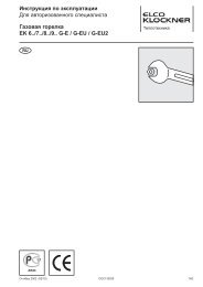
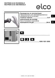
ADJUSTMENT OF GAS MINIMUM PRESSURE SWITCH<br />
Unscrew off and remove cover M. - Set regulator N to a value equal to 60% of gas nominal<br />
feed pressure (i.e. for nat. gas nom. pressure = 20 mbar, set regulator to a value of 12 mbar;<br />
for L.P.G. nom. pressure of G30/G31- 30/37 mbar, set regulator to a value of 18<br />
mbar).Screw up cover M<br />
ADJUSTMENT OF THE AIR PRESSURE SWITCH<br />
Unscrew screws A and B and remove cover C.- Set the pressure switch to the minimum<br />
by turning regulator D to position 1.<br />
- Start the burner and keep in low flame running, while checking that combustion is<br />
correct. Through a small cardboard, progressively obstruct the air intake until to<br />
obtain a CO2 increase of 0,5÷0,8% or else, if a pressure gauge is available, connected<br />
to pressure port E, until reaching a pressure drop of 1 mbar (10 mm of W.G.). -<br />
Slowly increase the adjustment value of the air pressure switch until to have the burner<br />
lockout. Remove the obstruction from the air intake, screw on the cover C and<br />
start the burner by pressing the control box rearm button.<br />
Note: The pressure measured at pressure port E must be within the limits of the<br />
pressure switch working range. If not, loose the locking nut of screw F and gradually<br />
turn the same: clockwise to reduce the pressure; counterclockwise to increase. At the<br />
end tighten the locking nut.<br />
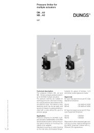
UV Fotocellula<br />
CELL<br />
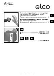
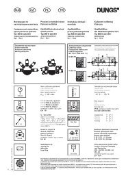
POSITION OF IGNITION ELECTRODES<br />
Microamperometer<br />
Microamperometro<br />
fondo<br />
full scale<br />
scala<br />
1000<br />
1000<br />
µA<br />
µA<br />
min 70 µA<br />
DETECTOR CURRENT<br />
LANDIS<br />
LFL 1.333<br />
1.622<br />
22 23<br />
3 ÷ 4 mm<br />
6<br />
I<br />
A<br />
5 ÷ 6 mm<br />
The detector current is checked by inserting a microammeter<br />
(scale 1000 µA - d.c.) in series with the uv cell..<br />
The flame detector current has to been > 70 µA.<br />
M<br />
C<br />
gas pressure<br />
switch<br />
L<br />
air pressure switch<br />
NOZZLE CLEANING AND REPLACEMENT<br />
Use only the suitable box wrench provided for this operation to remove the nozzle, taking care to not damage the electrodes.<br />
Fit the new nozzle with the same care.<br />
Note: Always check the position of electrodes after having replaced the nozzle (see illustration). A wrong position could<br />
cause ignition troubles.<br />
B<br />
50<br />
3,0<br />
45<br />
40<br />
2,5 5 10<br />
2,7<br />
N<br />
2,4<br />
D<br />
0,4 0,6<br />
G<br />
35<br />
2,1<br />
15<br />
30<br />
1,8<br />
0,9<br />
25<br />
20<br />
1,5<br />
1,2<br />
F<br />
H<br />
E