GHO-Tron 5 R RUS
GHO-Tron 5 R RUS
GHO-Tron 5 R RUS

You also want an ePaper? Increase the reach of your titles
YUMPU automatically turns print PDFs into web optimized ePapers that Google loves.
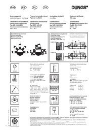
COMMUTATORE<br />
SELECTOR<br />
0<br />
AUTO<br />
-<br />
CALCULATING THE BURNER CAPACITY<br />
AIR AND GAS ADJUSTMENT<br />
Part. 1<br />
Part. 2<br />
To calculate the burner's capacity in kW, proceed as follows: Check the gas flow rate (in liters) on<br />
the counter and the time of the reading in seconds.<br />
Proceed with the calculation using the following : e x f = kW<br />
sec<br />
+<br />
0 = operating bloccaggio elements degli apparati locked per il in an intermediate<br />
position funzionamento in una posizione intermadia<br />
= operation funzionamento on maximum alla massima capacity potenza<br />
= operation funzionamento on minimum alla minima capacity potenza<br />
AUTO = automatic funzionamento operation automatico<br />
5<br />
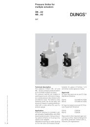
420010264101 <strong>GHO</strong> - TRON 5.5000 / 5.5800 R<br />
f<br />
--<br />
Part. 3<br />
ADJUSTING THE MINIMUM CAPACITY OF THE BURNER – AIR and GAS<br />
Position the selector placed on the control panel on position 2 and proceed as follows:<br />
Adjust the minimum gas flow rate using a suitable wrench, turn the butterfly valve until you reach the correct gas flow,<br />
as established by analyzing the combustion process.<br />
ADJUSTING THE MAXIMUM CAPACITY OF THE GAS<br />
Position the selector, situated on the control panel, on position 1 and proceed as follows:<br />
Adjusting the maximum gas flow rate (see figure on solenoid valve adjustments) or adjust the gas pressure in the governor.<br />
ADJUSTING THE MAXIMUM AIR FLOW RATE<br />
Adjusting the maximum air flow rate (see figure, detail 2). Loosen the nut holding the air damper transmission rod;<br />
The correct air flow as established by analyzing the combustion process.<br />
ADJUSTING THE INTERMEDIATE BURNER CAPACITY<br />
Using the selector, start the servomotor (closing or opening) and position on 0 to stop the stroke; the adjustment is<br />
made as outlined below. Repeat the operation for the other cam points.<br />
Adjustment the intermediate gas flow rates (see figure, detail 3): - using a suitable Allen wrench, change the position of<br />
the cam guide blade; if you screw it down, the flow rate is reduced; if you unscrew it, the flow rate increases.<br />
e = Litres gas<br />
sec = Time in second<br />
G20 = 34,02<br />
G30 = 116<br />
G31 = 88<br />
+<br />
EN