GHO-Tron 5 R RUS
GHO-Tron 5 R RUS
GHO-Tron 5 R RUS

Create successful ePaper yourself
Turn your PDF publications into a flip-book with our unique Google optimized e-Paper software.
EN<br />
420010264101 <strong>GHO</strong> - TRON 5.5000 / 5.5800 R<br />
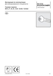
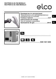
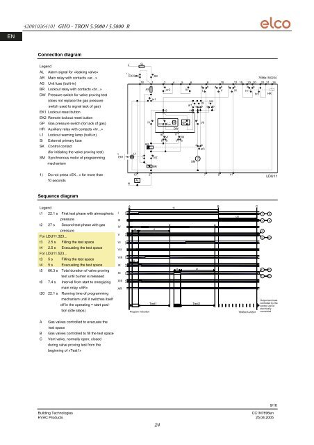
Connection diagram<br />
Legend<br />
AL Alarm signal for «leaking valve»<br />
AR Main relay with contacts «ar...»<br />
AS Unit fuse (built-in)<br />
BR Lockout relay with contacts «br...»<br />
DW Pressure switch for valve proving test<br />
(does not replace the gas pressure<br />
switch used to signal lack of gas)<br />
EK1 Lockout reset button<br />
EK2 Remote lockout reset button<br />
GP Gas pressure switch (for lack of gas)<br />
HR Auxiliary relay with contacts «hr...»<br />
L1 Lockout warning lamp (built-in)<br />
Si External primary fuse<br />
SK Control contact<br />
(for initiating the valve proving test)<br />
SM Synchronous motor of programming<br />
mechanism<br />
1) Do not press «EK...» for more than<br />
10 seconds<br />
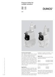
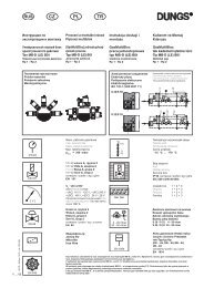
Sequence diagram<br />
Legend<br />
t1 22.1 s First test phase with atmospheric<br />
pressure<br />
t2 27 s Second test phase with gas<br />
pressure<br />
For LDU11.323...<br />
t3 2.5 s Filling the test space<br />
t4 2.5 s Evacuating the test space<br />
For LDU11.523...<br />
t3 5 s Filling the test space<br />
t4 5 s Evacuating the test space<br />
t5 66.3 s Total duration of valve proving<br />
test until burner is released<br />
t6 7.4 s Interval from start to energizing<br />
main relay «AR»<br />
t20 22.1 s Running time of programming<br />
mechanism until it switches itself<br />
off in the operating = start position<br />
(idle steps)<br />
A Gas valves controlled to evacuate the<br />
test space<br />
B Gas valves controlled to fill the test space<br />
C Vent valve, normally open; closed<br />
during valve proving test from the<br />
beginning of «Test1»<br />
1)<br />
EK1<br />
I<br />
III<br />
IV<br />
V<br />
VI<br />
VII<br />
VIII<br />
IX<br />
XI<br />
XIII<br />
AR<br />
L<br />
1)<br />
EK2<br />
a<br />
b<br />
a<br />
b<br />
a<br />
b<br />
a<br />
b<br />
a<br />
b<br />
a<br />
b<br />
a<br />
b<br />
N<br />
L1<br />
13<br />
AL<br />
Si<br />
SK<br />
18 1<br />
AS ar2<br />
AR<br />
IV<br />
br1<br />
br2<br />
BR<br />
Building Technologies CC1N7696en<br />
HVAC Products 25.04.2005<br />
24<br />
3 4 5<br />
III<br />
6<br />
ar1<br />
15 14<br />
Atm. Gas<br />
P<br />
DW<br />
GP<br />
16<br />
VI<br />
b a<br />
17<br />
VIII<br />
b a<br />
M<br />
~<br />
SM<br />
8<br />
a b<br />
I<br />
IX<br />
a b<br />
VII<br />
a b<br />
ar3<br />
a<br />
XIII<br />
b<br />
a b<br />
V<br />
2 7 9 11<br />
10 12 19 23 20<br />
a b a b<br />
XI hr1<br />
A B C<br />
t5<br />
t6<br />
t4 t1<br />
Program indication<br />
t3 t2<br />
Test1 Test2<br />
t20<br />
7696b01e/0601<br />
hr2<br />
7696a15/0204<br />
22 21 24<br />
HR<br />
7 8<br />
5 6<br />
9<br />
9 10<br />
11 15<br />
11 12<br />
LDU11<br />
Output terminals<br />
controlled by the<br />
control unit or<br />
electrically<br />
connected<br />
9/16