GHO-Tron 5 R RUS
GHO-Tron 5 R RUS
GHO-Tron 5 R RUS

You also want an ePaper? Increase the reach of your titles
YUMPU automatically turns print PDFs into web optimized ePapers that Google loves.
11<br />
420010264101 <strong>GHO</strong> - TRON 5.5000 / 5.5800 R<br />
MODULATING OPERATION<br />
With the bumer in the start position and the appliance thermostats enabled, power is delivered to the resi-<br />
stances (G) of the preheater and heating cartridges for the pumps and the fuel supply<br />
line to the head (O). When the preheater thermostat reaches the set value,<br />
(usually a minimum of about 90°C is necessary to guarantee a good level of circulation)<br />
the pump start-up is enabled (set point on out 1, if using the GEFRAN 200<br />
thermoregulating device). If the preheating system of the tank is also equipped for a<br />
fluid exchanger (hot water, steam, diathermic oil) the thermostat may enable a contact in the terminal<br />
block for any stop-start of the fluid electrovalve. This is not a standard solution as the heated fluid is normally<br />
always connected. The pump starts to send oil (the head has already been heated by its cartridge (O)<br />
and therefore has no residue of cold dense oil) which flows from the tank to the head and then to the<br />
return line of the ring. When the head thermostat reaches the set value (usually about 70-30°C the cycle<br />
starts properly and the control programmer enables start-up. The servomotor sets itself at minimum (see<br />
chapter on regulation) acting on the air and fùel via the pressure regulator on the return.<br />
The electromagnet (A) opens the nozzle (Q) in the followmg condition :<br />
- sparks from the ignition electrodes are generated by the transformer also governed by the burner<br />
control device.<br />
If the cell fails to detect the flame the burner shuts down (with the cyclic control programmer cutting in).<br />
Once ignition has taken place and after the flame stabilisation period, the system starts operating in modulating<br />
mode.<br />
- Before start-up make sure that the pump and delivery pipes are completely filled with hot fuel oil; the<br />
absence of fuel oil can cause pump seizure.<br />
- If there is a block, a specific waring light on the programmer and on the burner front control board<br />
lights up and this signal is usually sent to the main control board of the equipment using the burner,<br />
setting off a buzzer and warning light.<br />
- A few blocks are normal on first starting up (up to about 4); to release press the button on the<br />
programmer (also found on the front of the bumer control board) for repeating the start cycle. Should<br />
they continue to occur seek the help of a specialised technician.<br />
N.B. The position of the programmer at the time of the block is memorised to supply an indication of the<br />
cause of this block.<br />
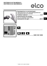
OIL DELIVERY ADJUSTMENT<br />
The diagram illustrates the fuel feeding system of these types of burners, which incorporates<br />
a by-pass nozzle with oil flow regulation on its return pipe. The oil supply is<br />
varied by acting on the nozzle through the pressure in the return line. Max. oil supply<br />
is therefore reached when the pressure in the pump line is about 22 bar and the return<br />
line is fully closed; min. oil supply when the return line is fully open. Relevant pressure<br />
readings in the return line are as follows:<br />
Pump pressure 22-25 bar.<br />
Max Burner output, return oil pressure:<br />
FLUIDICS nozzle : 16 ÷19 bar.<br />
BERGONZO nozzle : 20 ÷24 bar.<br />
Min Burner output, return oil pressure:<br />
FLUIDICS nozzle : 6 ÷9 bar<br />
BERGONZO nozzle : 4 ÷8 bar<br />
0 - STOP<br />
1 - GASOLIO HEAVY-OIL<br />
2 - GAS 0<br />
+<br />
-<br />
1<br />
2<br />
EN