Natural smartness in Hypothetical animals Of paddlers ... - Cogprints
Natural smartness in Hypothetical animals Of paddlers ... - Cogprints
Natural smartness in Hypothetical animals Of paddlers ... - Cogprints

Create successful ePaper yourself
Turn your PDF publications into a flip-book with our unique Google optimized e-Paper software.
<strong>Natural</strong> <strong>smartness</strong><br />
<strong>in</strong><br />
<strong>Hypothetical</strong> <strong>animals</strong><br />
<strong>Of</strong> <strong>paddlers</strong> and glowballs<br />
René Bert<strong>in</strong>
<strong>Natural</strong> <strong>smartness</strong><br />
<strong>in</strong><br />
<strong>Hypothetical</strong> <strong>animals</strong><br />
<strong>Of</strong> <strong>paddlers</strong> and glowballs
<strong>Natural</strong> <strong>smartness</strong><br />
<strong>in</strong><br />
<strong>Hypothetical</strong> <strong>animals</strong><br />
<strong>Of</strong> <strong>paddlers</strong> and glowballs<br />
Natuurlijke bijdehandigheidjes <strong>in</strong> hypothetische organismen<br />
Van peddelaars en ballen die gloeien<br />
(met een samenvatt<strong>in</strong>g <strong>in</strong> het Nederlands)<br />
PROEFSCHRIFT<br />
ter verkrijg<strong>in</strong>g van de graad van doctor<br />
aan de Universiteit Utrecht<br />
op gezag van de Rector Magnificus<br />
Prof. Dr. J.A. van G<strong>in</strong>kel<br />
volgens besluit van het College van Decanen<br />
<strong>in</strong> het openbaar te verdedigen op<br />
maandag 6 juni 1994 des namiddags te 2.30 uur<br />
door<br />
geboren op 2 maart 1967 te Utrecht<br />
ené¡ ean¢ ictor£ ert<strong>in</strong>
Promotor: Prof. Dr. Ir. W.A. van de Gr<strong>in</strong>d<br />
CIP-DATA KONINKLIJKE BIBLIOTHEEK, DEN HAAG<br />
Bert<strong>in</strong>, René Jean Victor<br />
<strong>Natural</strong> <strong>smartness</strong> <strong>in</strong> hypothetical <strong>animals</strong> : of <strong>paddlers</strong><br />
and glowballs / René Jean Victor Bert<strong>in</strong>. — Utrecht :<br />
Universiteit Utrecht, Faculteit Biologie<br />
Thesis Universiteit Utrecht. — With <strong>in</strong>dex, ref. — With<br />
summary <strong>in</strong> Dutch.<br />
ISBN 90-393-0742-3<br />
Subject head<strong>in</strong>gs: neuro-ethology / artificial life /<br />
biological cybernetics.
à Euterpe et les autres.<br />
t is an important and popular fact that th<strong>in</strong>gs are not always what they seem. For<br />
<strong>in</strong>stance, on the planet Earth, man had always assumed that he was more <strong>in</strong>telligent<br />
than dolph<strong>in</strong>s because he had achieved so much — the wheel, New York, wars and<br />
so on — whilst all the dolph<strong>in</strong>s had ever done was muck about <strong>in</strong> the water hav<strong>in</strong>g<br />
a good time. But conversely, the dolph<strong>in</strong>s had always believed that they were far<br />
more <strong>in</strong>telligent than man – for precisely the same reasons.<br />
¤<br />
Curiously enough, the dolph<strong>in</strong>s had long known of the impend<strong>in</strong>g destruction of<br />
the planet Earth and had made many attempts to alert mank<strong>in</strong>d to the danger; but<br />
most of their communications were mis<strong>in</strong>terpreted ...<br />
Douglas Adams, The Hitch-Hikers’ Guide To The Galaxy
dy<br />
dx<br />
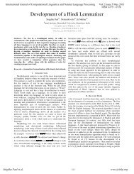
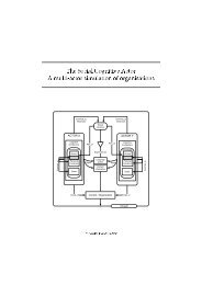
A uniform glowball distribution<br />
is disturbed by add<strong>in</strong>g a value<br />
random(n*dx) , random(n*dy) to<br />
the glowball coord<strong>in</strong>ates<br />
The "m<strong>in</strong>imal" distance to a neighbour<br />
can be the shortest distance, with with-<br />
drawal of glowballs, or the distance<br />
to the most attractive (closest/largest)<br />
glowball with<strong>in</strong> a certa<strong>in</strong> w<strong>in</strong>dow of<br />
direction relative to a glowball<br />
previously attached to the tree.<br />
Every Glowball has a drift vector<br />
which def<strong>in</strong>es a motion bounc<strong>in</strong>g<br />
around <strong>in</strong> a rectangle. These<br />
rectangles are clipped at the edges<br />
of the "World". The drift vector is<br />
specified as per-timestep x and<br />
y deplacements with a variable<br />
percentage of noise added to them.<br />
The average distance to the nearest<br />
neighbour (the average m<strong>in</strong>imal distance)<br />
is used to qualify the "World".<br />
Distance covered per glowball over<br />
AvM<strong>in</strong>Dist turns out to be a good<br />
paddler performance criterium.
Contents<br />
I <strong>Natural</strong> <strong>smartness</strong> <strong>in</strong> <strong>Hypothetical</strong> <strong>animals</strong> 11<br />
<strong>in</strong>troduction¥¦¥§¥¦¥§¥¦¥¨¥§¥¦¥§¥¦¥¦¥§¥¦¥§¥¦¥¨¥§¥¦¥§¥¦¥¦¥§¥¦¥§¥¦¥¨¥§¥¦¥§¥¦¥¦¥§¥ <strong>smartness</strong>¥¦¥¦¥§¥¦¥§¥¨¥¦¥§¥¦¥§¥¦¥¦¥§¥ ¥§¥¦¥§¥¨¥¦¥§¥¦¥§¥¦¥¦¥§¥¦¥§¥¨¥¦¥§¥¦¥§¥¦¥¦¥§¥¦¥§¥¨¥¦¥§¥¦¥§¥¦¥¦¥§¥ modell<strong>in</strong>g¥¨¥¦¥§¥¦¥§¥¦¥¦¥§¥¦¥§¥¨¥¦¥§¥¦¥§¥¦¥¦¥§¥¦¥¦¥¦¥¦¥§¥ thesis¥§¥¨¥¦¥§¥¦¥§¥¦¥¦¥§¥¦¥§¥¨¥¦¥§¥¦¥§¥¦¥¦¥§¥¦¥§¥¨¥¦¥§¥¦¥§¥¦¥¦¥§¥ attempt¥¦¥§¥¦¥¦¥§¥¨¥§¥¦¥¦¥§¥¦¥§¥¦¥¦¥§¥¨¥§¥¦¥¦¥§¥ glowballs¥¦¥¦¥¦¥§¥ evolution¥¦¥¦¥§¥¨¥§¥¦¥¦¥§¥¦¥§¥¦¥¦¥§¥¨¥§¥¦¥¦¥§¥ ¥§¥¦¥¦¥§¥¦¥§¥¨¥¦¥§¥¦¥§¥¦¥¦¥§¥¦¥§¥¨¥¦¥§¥¦¥§¥¦¥¦¥§¥¦¥§¥¨¥¦¥§¥<br />
1 Introduction 13<br />
1.1 General 14<br />
1.1.1 Artificial <strong>in</strong>telligence versus natural 14<br />
1.2 Modell<strong>in</strong>g Behaviour 16<br />
1.2.1 Neuro-ethological 18<br />
1.3 An overview of this 23<br />
1.3.1 A hypothetical modell<strong>in</strong>g 23<br />
1.3.2 A more realistic modell<strong>in</strong>g attempt: of <strong>paddlers</strong> and 26<br />
1.3.3 A snapshot of the paddler’s 27<br />
1.3.4 Some conclusions 29<br />
¥¦¥¦¥§¥¦¥¦¥§¥¦¥§¥¨¥¦¥§¥¦¥§¥¦¥¦¥§¥¦¥¦¥¦¥¦¥§¥¦¥§¥¦¥¦¥§¥¨¥§¥¦¥¦¥§¥¦¥§¥¦¥¦¥§¥ habitat¥¦¥§¥¦¥§¥¦¥¦¥¦¥¦¥§¥¦¥¦¥§¥¦¥§¥¦¥¨¥§¥¦¥§¥¦¥¦¥§¥¦¥§¥¦¥¨¥§¥ anatomy¥§¥¦¥§¥¦¥¦¥§¥¦¥§¥¦¥¨¥§¥¦¥§¥¦¥¦¥§¥¦¥§¥¨¥¦¥§¥¦¥§¥¦¥¦¥§¥ Methods¥§¥¦¥§¥¨¥¦¥§¥¦¥¦¥§¥¦¥§¥¦¥¨¥§¥¦¥§¥¦¥¦¥§¥¦¥§¥¦¥¨¥§¥¦¥§¥¦¥¦¥§¥¦¥§¥¨¥¦¥§¥¦¥§¥¦¥¦¥§¥ ¥§¥¦¥¦¥§¥¦¥¦¥§¥¦¥§¥¨¥¦¥§¥¦¥§¥¦¥¦¥§¥¦¥§¥¨¥¦¥§¥¦¥§¥¦¥¦¥§¥¦¥¦¥¦¥¦¥§¥¦¥§¥¦¥¦¥§¥<br />
2 <strong>Hypothetical</strong> visually-guided <strong>animals</strong> 33<br />
2.1 Introduction 34<br />
2.2 The <strong>animals</strong> and their 35<br />
2.2.1 The paddler’s 35<br />
2.3 40<br />
2.4 Discussion 48<br />
¥¦¥¦¥§¥¦¥¦¥§¥¦¥§¥¨¥¦¥§¥¦¥§¥¦¥¦¥§¥¦¥¦¥¦¥¦¥§¥¦¥§¥¦¥¦¥§¥¨¥§¥¦¥¦¥§¥¦¥§¥¦¥¦¥§¥ pr<strong>in</strong>ciples¥§¥¦¥¨¥§¥¦¥§¥¦¥¦¥§¥¦¥§¥¦¥¨¥§¥¦¥§¥¦¥¦¥§¥¦¥§¥¦¥¨¥§¥ ret<strong>in</strong>a¥¦¥¦¥§¥¦¥§¥¦¥¦¥§¥¨¥§¥¦¥¦¥§¥¦¥§¥¦¥¦¥§¥ bra<strong>in</strong>¥¦¥§¥¦¥§¥¦¥¦¥§¥¨¥§¥¦¥¦¥§¥¦¥§¥¦¥¦¥§¥ ¥¨¥§¥¦¥§¥¦¥¦¥§¥¦¥§¥¦¥¨¥§¥¦¥§¥¦¥¦¥§¥¦¥§¥¨¥¦¥§¥ ¥¦¥§¥¨¥§¥¦¥¦¥§¥¦¥§¥¦¥¦¥§¥¨¥§¥¦¥¦¥§¥¦¥§¥¦¥¨¥§¥ Methods¥§¥¦¥§¥¨¥¦¥§¥¦¥¦¥§¥¦¥§¥¦¥¨¥§¥¦¥§¥¦¥¦¥§¥¦¥§¥¦¥¨¥§¥¦¥§¥¦¥¦¥§¥¦¥§¥¨¥¦¥§¥¦¥§¥¦¥¦¥§¥ performances¥¦¥§¥¦¥§¥¦¥¦¥§¥¦¥§¥¨¥¦¥§¥¦¥§¥¦¥¦¥§¥¦¥§¥¨¥¦¥§¥¦¥§¥¦¥¦¥§¥ Simulations¥¦¥¨¥§¥¦¥§¥¦¥¦¥§¥¦¥§¥¨¥¦¥§¥¦¥§¥¦¥¦¥§¥¦¥§¥¨¥¦¥§¥¦¥§¥¦¥¦¥§¥¦¥§¥¨¥¦¥§¥ ¥§¥¦¥§¥¨¥¦¥§¥¦¥¦¥§¥¦¥§¥¦¥¨¥§¥¦¥§¥¦¥¦¥§¥¦¥§¥¨¥¦¥§¥¦¥§¥¦¥¦¥§¥¦¥§¥¨¥¦¥§¥¦¥§¥¦¥¦¥§¥ Weber-mach<strong>in</strong>e¥¦¥¦¥§¥¦¥§¥¨¥¦¥§¥¦¥§¥¦¥¦¥§¥¦¥§¥¨¥¦¥§¥ ¥§¥¦¥¨¥§¥¦¥§¥¦¥¦¥§¥¦¥§¥¨¥¦¥§¥¦¥§¥¦¥¦¥§¥¦¥§¥¨¥¦¥§¥¦¥§¥¦¥¦¥§¥ ¥§¥¦¥¦¥§¥¦¥¦¥§¥¦¥§¥¨¥¦¥§¥¦¥§¥¦¥¦¥§¥¦¥§¥¨¥¦¥§¥¦¥§¥¦¥¦¥§¥¦¥¦¥¦¥¦¥§¥¦¥§¥¦¥¦¥§¥<br />
3 Light adaptation <strong>in</strong> the paddler 53<br />
3.1 Introduction 54<br />
3.1.1 Light adaptation 55<br />
3.1.2 Light adaptation <strong>in</strong> the paddler 57<br />
3.1.3 A brief overview of the paddler’s 60<br />
3.1.4 Body geometry of the paddler 62<br />
3.1.5 Scope of this simulation study 63<br />
3.2 64<br />
3.2.1 Judg<strong>in</strong>g 64<br />
3.2.2 66<br />
3.3 Results 66<br />
3.3.1 Time constants of the 66<br />
3.3.2 Lateral <strong>in</strong>hibition 68<br />
3.4 Discussion 71<br />
¥¦¥¦¥§¥¦¥¦¥§¥¦¥§¥¨¥¦¥§¥¦¥§¥¦¥¦¥§¥¦¥¦¥¦¥¦¥§¥¦¥§¥¦¥¦¥§¥¨¥§¥¦¥¦¥§¥¦¥§¥¦¥¦¥§¥ ¥¦¥§¥¦¥§¥¦¥¦¥¦¥¦¥§¥¦¥¦¥§¥<br />
4 The paddle controller 77<br />
4.1 Introduction 78<br />
4.1.1 Oscillators <strong>in</strong> the paddler: the paddle controller 78<br />
7
8 Contents<br />
Generators¥¦¥¦¥§¥¦¥§¥¦¥¦¥§¥ ¥¨¥¦¥§¥¦¥§¥¦¥¦¥§¥¦¥§¥¨¥¦¥§¥¦¥§¥¦¥¦¥§¥ ¥¦¥§¥¦¥¦¥§¥¨¥§¥¦¥¦¥§¥¦¥§¥¦¥¦¥§¥¨¥§¥¦¥¦¥§¥¦¥§¥¦¥¦¥§¥ ¥¦¥§¥¦¥§¥¦¥¨¥§¥¦¥§¥¦¥¦¥§¥¦¥§¥¦¥¨¥§¥¦¥§¥¦¥¦¥§¥ neurone¥¦¥¨¥§¥¦¥§¥¦¥¦¥§¥¦¥§¥¦¥¨¥§¥¦¥§¥¦¥¦¥§¥¦¥§¥¨¥¦¥§¥ ¥¨¥§¥¦¥§¥¦¥¦¥§¥¦¥§¥¦¥¨¥§¥¦¥§¥¦¥¦¥§¥¦¥§¥¦¥¨¥§¥¦¥§¥¦¥¦¥§¥ controller¥¦¥§¥¦¥§¥¦¥¨¥§¥¦¥§¥¦¥¦¥§¥¦¥§¥¦¥¨¥§¥¦¥§¥¦¥¦¥§¥ oscillator¥¦¥¨¥§¥¦¥§¥¦¥¦¥§¥¦¥§¥¦¥¨¥§¥¦¥§¥¦¥¦¥§¥¦¥§¥¨¥¦¥§¥ oscillator¥§¥¨¥§¥¦¥¦¥§¥¦¥§¥¦¥¦¥¦¥ ¥¦¥§¥¦¥¨¥§¥¦¥§¥¦¥¦¥§¥ oscillator¥¦¥§¥¦¥§¥¦¥¦¥§¥¨¥§¥¦¥¦¥§¥¦¥§¥¦¥¦¥§¥¨¥§¥¦¥¦¥§¥ self-<strong>in</strong>hibition¥¦¥§¥¨¥¦¥§¥¦¥§¥¦¥¦¥§¥¦¥§¥¨¥¦¥§¥¦¥§¥¦¥¦¥§¥<br />
4.1.2 Oscillations, Oscillators and Central Pattern 78<br />
4.1.3 Requirements for a paddle controller 80<br />
4.1.4 Overview of this chapter 81<br />
4.2 Models of Central Pattern Generators 83<br />
4.2.1 A model pacemaker 83<br />
4.2.2 Pacemaker networks 83<br />
4.3 An oscillator for the paddle 88<br />
4.3.1 Classification of the 88<br />
4.3.2 Feedback control of the dynamics of the 89<br />
4.3.3 An oscillator with shunt<strong>in</strong>g delayed self-<strong>in</strong>hibition 94<br />
4.3.4 Behaviour of a type-2 96<br />
4.3.5 Reset of the delayed 97<br />
4.3.6 Formal description of the type-2 oscillator ¥¦¥§¥¦¥¦¥§¥¨¥§¥¦¥¦¥§¥¦¥§¥¦¥¦¥§¥100<br />
4.4 Us<strong>in</strong>g the paddle controller¥¦¥¦¥§¥¦¥§¥¦¥¦¥§¥¨¥§¥¦¥¦¥§¥¦¥§¥¦¥¦¥§¥¨¥§¥¦¥¦¥§¥¦¥§¥¦¥¦¥§¥102<br />
4.4.1 Convert<strong>in</strong>g a paddl<strong>in</strong>g movement <strong>in</strong>to thrust¥§¥¦¥¦¥§¥¨¥§¥¦¥¦¥§¥¦¥§¥¦¥¦¥¦¥102<br />
4.4.2 Test of the type-2 thrust controller <strong>in</strong> a "really paddl<strong>in</strong>g" paddler¥¦¥¦¥§¥106<br />
4.5 Conclud<strong>in</strong>g remarks¥¦¥§¥¦¥§¥¦¥¦¥§¥¨¥§¥¦¥¦¥§¥¦¥§¥¦¥¦¥§¥¨¥§¥¦¥¦¥§¥¦¥§¥¦¥¨¥§¥¦¥§¥¦¥¦¥§¥113<br />
4.5.1 Overview of a paddle/thrust controller¥¦¥§¥¦¥§¥¦¥¦¥§¥¨¥§¥¦¥¦¥§¥¦¥§¥¦¥¦¥§¥113<br />
4.5.2 Conclusions ¥¦¥§¥¨¥§¥¦¥¦¥§¥¦¥§¥¦¥¦¥§¥¨¥§¥¦¥¦¥§¥¦¥§¥¦¥¦¥¦¥¦¥§¥¦¥¦¥§¥¦¥§¥¦¥¨¥§¥115<br />
5 The speed control system 119<br />
5.1 Introduction ¥¦¥¦¥§¥¦¥¦¥§¥¦¥§¥¨¥¦¥§¥¦¥§¥¦¥¦¥§¥¦¥¦¥¦¥¦¥§¥¦¥§¥¦¥¦¥§¥¨¥§¥¦¥¦¥§¥¦¥§¥¦¥¦¥§¥120<br />
5.1.1 Control systems ¥¦¥§¥¦¥¦¥§¥¦¥§¥¦¥¨¥§¥¦¥§¥¦¥¦¥§¥¦¥§¥¨¥¦¥§¥¦¥§¥¦¥¦¥§¥¦¥§¥¨¥¦¥§¥120<br />
5.1.2 Overview of this chapter ¥¦¥§¥¦¥¦¥§¥¨¥§¥¦¥¦¥§¥¦¥§¥¦¥¦¥§¥¨¥§¥¦¥¦¥§¥¦¥§¥¦¥¦¥§¥121<br />
5.2 Sensory perception <strong>in</strong> ego-motion control¥¦¥§¥¦¥¦¥§¥¦¥§¥¨¥¦¥§¥¦¥§¥¦¥¦¥§¥¦¥§¥¨¥¦¥§¥122<br />
5.2.1 Role of the cerebellum¥¦¥§¥¦¥§¥¦¥¦¥§¥¦¥§¥¨¥¦¥§¥¦¥§¥¦¥¦¥§¥¨¥§¥¦¥¦¥§¥¦¥§¥¦¥¦¥§¥122<br />
5.2.2 Flight stabilisation <strong>in</strong> the fly ¥¦¥¨¥§¥¦¥§¥¦¥¦¥§¥¦¥§¥¦¥¨¥§¥¦¥§¥¦¥¦¥§¥¦¥§¥¨¥¦¥§¥124<br />
5.2.3 The w<strong>in</strong>d hair system <strong>in</strong> locust¥¦¥¦¥¦¥§¥¦¥¦¥§¥¦¥§¥¦¥¨¥§¥¦¥§¥¦¥¦¥§¥¦¥§¥¦¥¨¥§¥125<br />
5.3 A model for a speed control system <strong>in</strong> <strong>paddlers</strong> ¥§¥¦¥§¥¦¥¦¥§¥¨¥§¥¦¥¦¥§¥¦¥§¥¦¥¦¥§¥128<br />
5.3.1 The perception of speed¥§¥¦¥§¥¦¥¦¥§¥¦¥§¥¦¥¨¥§¥¦¥§¥¦¥¦¥§¥¦¥§¥¨¥¦¥§¥¦¥§¥¦¥¦¥§¥128<br />
5.3.2 The expected speed ¥¦¥¦¥§¥¨¥§¥¦¥¦¥§¥¦¥§¥¦¥¦¥§¥¨¥§¥¦¥¦¥§¥¦¥§¥¦¥¨¥§¥¦¥§¥¦¥¦¥§¥131<br />
5.3.3 Determ<strong>in</strong>ation of the elementary ga<strong>in</strong> factors¥§¥¨¥¦¥§¥¦¥§¥¦¥¦¥§¥¦¥§¥¨¥¦¥§¥135<br />
5.3.4 Determ<strong>in</strong>ation of the speed ga<strong>in</strong> factor ¥¨¥§¥¦¥§¥¦¥¦¥§¥¦¥§¥¨¥¦¥§¥¦¥§¥¦¥¦¥§¥138<br />
5.3.5 Determ<strong>in</strong>ation of the brake command¥¦¥¦¥§¥¨¥§¥¦¥¦¥§¥¦¥§¥¦¥¦¥¦¥¦¥§¥¦¥¦¥§¥140<br />
5.3.6 Performance of the speed control system ¥§¥¦¥§¥¦¥¦¥§¥¦¥§¥¦¥¨¥§¥¦¥§¥¦¥¦¥§¥141<br />
5.3.7 Summary¥§¥¦¥¦¥§¥¨¥§¥¦¥¦¥§¥¦¥§¥¦¥¨¥§¥¦¥§¥¦¥¦¥§¥¦¥§¥¦¥¨¥§¥¦¥§¥¦¥¦¥§¥¦¥§¥¦¥¨¥§¥147<br />
5.4 Use of the speed control system ¥¦¥§¥¦¥¦¥§¥¦¥§¥¨¥¦¥§¥¦¥§¥¦¥¦¥§¥¦¥§¥¨¥¦¥§¥¦¥§¥¦¥¦¥§¥148<br />
5.5 Conclud<strong>in</strong>g remarks¥¦¥§¥¦¥§¥¦¥¦¥§¥¨¥§¥¦¥¦¥§¥¦¥§¥¦¥¦¥§¥¨¥§¥¦¥¦¥§¥¦¥§¥¦¥¨¥§¥¦¥§¥¦¥¦¥§¥158<br />
5.5.1 Experiments <strong>in</strong> the sp<strong>in</strong>al paddler¥¦¥§¥¦¥¨¥§¥¦¥§¥¦¥¦¥§¥¦¥§¥¦¥¨¥§¥¦¥§¥¦¥¦¥§¥160<br />
5.5.2 Experiments <strong>in</strong> the <strong>in</strong>tact paddler ¥¦¥§¥¦¥¦¥§¥¨¥§¥¦¥¦¥§¥¦¥§¥¦¥¨¥§¥¦¥§¥¦¥¦¥§¥161<br />
5.5.3 Different paddle positions ¥§¥¦¥¨¥§¥¦¥§¥¦¥¦¥§¥¦¥§¥¦¥¨¥§¥¦¥§¥¦¥¦¥§¥¦¥§¥¦¥¨¥§¥162<br />
5.5.4 Paddl<strong>in</strong>g with the tailf<strong>in</strong> ¥¦¥§¥¦¥¦¥¦¥¦¥§¥¦¥¦¥§¥¦¥§¥¦¥¨¥§¥¦¥§¥¦¥¦¥§¥¦¥§¥¦¥¨¥§¥162<br />
5.5.5 What rema<strong>in</strong>s to be done ¥¦¥§¥¦¥¦¥§¥¦¥§¥¦¥¨¥§¥¦¥§¥¦¥¦¥§¥¦¥§¥¦¥¨¥§¥¦¥§¥¦¥¦¥§¥163<br />
6 The motion detection system 165<br />
6.1 Introduction ¥¦¥¦¥§¥¦¥¦¥§¥¦¥§¥¨¥¦¥§¥¦¥§¥¦¥¦¥§¥¦¥¦¥¦¥¦¥§¥¦¥§¥¦¥¦¥§¥¨¥§¥¦¥¦¥§¥¦¥§¥¦¥¦¥§¥166<br />
6.1.1 Overview of this chapter ¥¦¥§¥¦¥¦¥§¥¨¥§¥¦¥¦¥§¥¦¥§¥¦¥¦¥§¥¨¥§¥¦¥¦¥§¥¦¥§¥¦¥¦¥§¥167<br />
6.2 Perception of motion <strong>in</strong> <strong>in</strong>vertebrates ¥¦¥§¥¦¥§¥¦¥¦¥§¥¨¥§¥¦¥¦¥§¥¦¥§¥¦¥¦¥§¥¨¥§¥¦¥¦¥§¥168<br />
6.2.1 The motion detection system of <strong>in</strong>sects ¥¦¥§¥¦¥§¥¨¥¦¥§¥¦¥§¥¦¥¦¥§¥¦¥§¥¨¥¦¥§¥168
Contents 9<br />
6.3 A model system for the detection of motion¥§¥¦¥¦¥§¥¨¥§¥¦¥¦¥§¥¦¥§¥¦¥¦¥§¥¨¥§¥¦¥¦¥§¥172<br />
6.3.1 Why motion detection?¥§¥¨¥§¥¦¥¦¥§¥¦¥§¥¦¥¦¥§¥¨¥§¥¦¥¦¥§¥¦¥§¥¦¥¦¥§¥¨¥§¥¦¥¦¥§¥172<br />
6.3.2 Before the EMD: the <strong>in</strong>put¥¦¥§¥¦¥¦¥§¥¦¥¦¥¦¥¦¥§¥¦¥§¥¦¥¦¥§¥¨¥§¥¦¥¦¥§¥¦¥§¥¦¥¦¥§¥177<br />
6.3.3 The elementary motion detector (EMD) ¥¨¥§¥¦¥§¥¦¥¦¥§¥¦¥§¥¦¥¨¥§¥¦¥§¥¦¥¦¥§¥181<br />
6.3.4 Beyond the EMD ¥¦¥§¥¦¥¦¥§¥¦¥§¥¦¥¨¥§¥¦¥§¥¦¥¦¥§¥¦¥§¥¨¥¦¥§¥¦¥§¥¦¥¦¥§¥¦¥§¥¨¥¦¥§¥183<br />
6.3.5 Central process<strong>in</strong>g of the movement <strong>in</strong>formation¥¨¥§¥¦¥§¥¦¥¦¥§¥¦¥§¥¦¥¨¥§¥187<br />
6.3.6 Use of the movement <strong>in</strong>formation¥¦¥§¥¦¥¦¥§¥¦¥§¥¨¥¦¥§¥¦¥§¥¦¥¦¥§¥¦¥§¥¨¥¦¥§¥193<br />
6.4 Experimental results¥¦¥§¥¦¥§¥¦¥¨¥§¥¦¥§¥¦¥¦¥§¥¦¥§¥¨¥¦¥§¥¦¥§¥¦¥¦¥§¥¦¥§¥¨¥¦¥§¥¦¥§¥¦¥¦¥§¥196<br />
6.4.1 Spatial resolution of the ret<strong>in</strong>a ¥¦¥§¥¦¥§¥¦¥¦¥§¥¨¥§¥¦¥¦¥§¥¦¥§¥¦¥¦¥§¥¨¥§¥¦¥¦¥§¥198<br />
6.4.2 Drift speed of the glowballs¥§¥¦¥¨¥§¥¦¥§¥¦¥¦¥§¥¦¥§¥¦¥¨¥§¥¦¥§¥¦¥¦¥§¥¦¥§¥¦¥¨¥§¥204<br />
6.5 Discussion ¥§¥¦¥¦¥§¥¦¥¦¥§¥¦¥§¥¨¥¦¥§¥¦¥§¥¦¥¦¥§¥¦¥§¥¨¥¦¥§¥¦¥§¥¦¥¦¥§¥¦¥¦¥¦¥¦¥§¥¦¥§¥¦¥¦¥§¥206<br />
6.5.1 Conclusion¥¦¥¦¥§¥¨¥§¥¦¥¦¥§¥¦¥§¥¦¥¦¥§¥¨¥§¥¦¥¦¥§¥¦¥§¥¦¥¦¥§¥¨¥§¥¦¥¦¥§¥¦¥§¥¦¥¨¥§¥209<br />
II Natuurlijke bijdehandigheidjes <strong>in</strong> hypothetische organismen 211<br />
7 Van peddelaars en ballen die gloeien 213<br />
III Appendices 221<br />
References 223<br />
Index 229<br />
Author Index 231<br />
Curriculum Vitae 233<br />
Dankwoord 235
10 Contents
<strong>Natural</strong> <strong>smartness</strong><br />
<strong>in</strong><br />
©<br />
<strong>Hypothetical</strong> <strong>animals</strong><br />
11
13<br />
Introduction
14 CHAPTER 1. INTRODUCTION<br />
1.1 General <strong>in</strong>troduction<br />
How, i.e. us<strong>in</strong>g what mechanisms, do we behave? That’s an age-old question that has<br />
through time boggled the m<strong>in</strong>ds of many a philosopher, homo universalis and researcher.<br />
And thought, where does that come from? Both apparently have someth<strong>in</strong>g to do with the<br />
nervous system, and, ultimately, the bra<strong>in</strong>.<br />
René Descartes supposed that the control of low level, bodily, behaviour takes place<br />
through levers, gears and str<strong>in</strong>gs, much like the early mechanical calculators, or the fly-bywire<br />
control of yesteryear’s airplanes. Thought, a product of man’s soul, was thought to<br />
be <strong>in</strong>dependant of these low level bodily processes. In his first assumption Descartes was<br />
probably closer to the truth than some people realise. His ideas on thought have even <strong>in</strong> this<br />
century been embraced by many, for example by the "hard core" artificial <strong>in</strong>telligence (AI)<br />
people. On this score Descartes may have been further from the truth then most of his recent<br />
followers realise.<br />
Thought, reason<strong>in</strong>g, cognitive processes and other mental processes are not to be treated<br />
<strong>in</strong> the follow<strong>in</strong>g text. These topics are simply still too complex, too much "top level".<br />
Contrary to Descartes, and contrary to the classical AI credo, it is <strong>in</strong>creas<strong>in</strong>gly popular to<br />
view thought, reason<strong>in</strong>g, etc. as emergent properties, as the result of the evolution of "simple"<br />
nervous systems designed <strong>in</strong>itially for simpler k<strong>in</strong>ds of behavioural control. They are just<br />
another form of behaviour. This appears to be a very healthy view to me. It is probably not<br />
necessary to expand on the advantages of the latter, and the disadvantages of the former (AI)<br />
approaches: enough <strong>in</strong>k has already been absorbed for that purpose (see e.g. Roger Penrose<br />
1990, or Randall Beer 1989).<br />
1.1.1 Artificial <strong>in</strong>telligence versus natural <strong>smartness</strong><br />
That theory is worthless. It isn’t even wrong!<br />
Wolfgang Pauli<br />
In the sky there is no dist<strong>in</strong>ction of east and west; people create dist<strong>in</strong>ctions out of their own<br />
m<strong>in</strong>ds and then believe them to be true<br />
Buddha<br />
In other words, <strong>in</strong>telligence should (at least partly) be regarded as a by-product of evolution,<br />
an epi-phenomenon. Take for example the k<strong>in</strong>d(s) of <strong>in</strong>telligence required for the LAT E X<br />
and C programm<strong>in</strong>g that produced the layout of this book and the "theoretical biologist’s<br />
look<strong>in</strong>g-glass" for the experiments described <strong>in</strong> follow<strong>in</strong>g chapters. Chess and sort<strong>in</strong>g (<strong>in</strong><br />
all its guises) are other favourate examples of <strong>in</strong>telligent behaviours. These examples of<br />
<strong>in</strong>telligence require a healthy dose of symbolic manipulation; they are actually abstractions<br />
of mechanical manipulations and transformations of real objects.<br />
For this reason tasks like the ones listed above can be automated <strong>in</strong> a relatively straightforward<br />
(though tedious) way. This much AI has managed, and <strong>in</strong> itself that is a quite<br />
formidable and useful feat. The underly<strong>in</strong>g <strong>in</strong>telligence that signed for compos<strong>in</strong>g (or understand<strong>in</strong>g)<br />
this text proper, or for the models simulated by said C programs, that k<strong>in</strong>d of<br />
<strong>in</strong>telligence is of an entirely different order of magnitude. Still it makes use of the same<br />
substrate, and therefore it seems likely that it also makes use of the same processes.
1.1. GENERAL INTRODUCTION 15<br />
One can argue about the evolutionary adaptive value of some of the k<strong>in</strong>ds of <strong>in</strong>telligence<br />
exemplified above, at least of the applications of these k<strong>in</strong>ds of <strong>in</strong>telligence. There are other<br />
forms and applications of <strong>in</strong>telligence whose survival value is far greater: ’a brilliant chess<br />
move while the room is fill<strong>in</strong>g with smoke because the house is burn<strong>in</strong>g down does not show<br />
<strong>in</strong>telligence’ (Anatol Holt, quoted <strong>in</strong> Beer 1989, page 10). The same processes will probably<br />
come <strong>in</strong>to play to clear a way out of the burn<strong>in</strong>g house, possibly sav<strong>in</strong>g other occupants. I<br />
th<strong>in</strong>k most will agree that this is <strong>in</strong>telligent behaviour with evolutionary adaptive value!<br />
These forms of <strong>in</strong>telligence are the ones that enable us to detect an upcom<strong>in</strong>g collision<br />
with a specific tree amidst the rest of the forest, that enable frogs and flies to detect and<br />
capture prey or mates respectively, Drosophilas to keep course or explore (see chapter 6), etc.<br />
These forms of <strong>in</strong>telligence are cunn<strong>in</strong>gly wired down <strong>in</strong> the nervous system, connect<strong>in</strong>g<br />
sensory organs with limbs, w<strong>in</strong>gs or f<strong>in</strong>s <strong>in</strong> a way that — <strong>in</strong> its functionality — closely<br />
resembles Descartes’ view of behavioural control. That is not to say that one should expect<br />
to f<strong>in</strong>d "neuronal correlates" of levers, gears or str<strong>in</strong>gs <strong>in</strong>side the nervous system. Instead one<br />
can expect to f<strong>in</strong>d a very well def<strong>in</strong>ed flow of <strong>in</strong>formation from the receptors respond<strong>in</strong>g to<br />
some stimulus, through <strong>in</strong>termediate layer(s) to the effectors effectuat<strong>in</strong>g the reaction to the<br />
stimulus. The neurones <strong>in</strong> the path taken <strong>in</strong>fluence each other <strong>in</strong> ways that — <strong>in</strong> the simpler<br />
cases — can be described <strong>in</strong> terms of levers, gears and str<strong>in</strong>gs. More complex <strong>in</strong>teractions<br />
are probably better described <strong>in</strong> terms of electronic components.<br />
The neural mechanisms that are so cunn<strong>in</strong>gly wired for a given transformation of sensory<br />
<strong>in</strong>formation have aptly been named smart mechanisms (Runeson 1977, van de Gr<strong>in</strong>d 1990).<br />
In fact they are similar to neural servo-mechanisms 1. The behaviour of <strong>in</strong>sects and other<br />
<strong>in</strong>vertebrates (e.g. the famous sea-slug Aplysia) can for a substantial part be described <strong>in</strong><br />
terms of smart mechanisms. More complex behaviours will eventually require additional<br />
wetware 2that can learn how to accomplish those behaviours. In fact this extends the use of<br />
smart mechanisms to problems where unforeseeable or chang<strong>in</strong>g variables — environmental,<br />
or morphological parameters like arm length — are <strong>in</strong>volved.<br />
Intelligence is not restricted to the nervous system. Purposeful morphological design<br />
makes an animal’s body a smart mechanism as well. Consider the Diesel-like 3design of<br />
the flight motor <strong>in</strong> flies: it is controlled by spikes that occur only every so many w<strong>in</strong>gbeats.<br />
The motion of the physical elements of the motor (muscles, thorax and w<strong>in</strong>gs) <strong>in</strong>duces the<br />
appropriate muscle contraction every w<strong>in</strong>gbeat half-cycle. The motor is also equipped with<br />
a kickstart: the same muscle that starts it also pushes the fly of its perch (see chapter 4).<br />
It seems appropriate to refer to the study of these smart mechanisms as the study of natural<br />
<strong>smartness</strong>. The same field is known by the name of neuro-ethology, the study of behaviour <strong>in</strong><br />
terms of its neural bases. The study presented <strong>in</strong> this thesis is concerned with the theoretical<br />
form of neuro-ethology. Theoretical neuro-ethology 4seeks to <strong>in</strong>tegrate neuro-ethological<br />
1 ’Un servo-mécanisme est un mécanisme auto-contrôlé dont la référence est variable et dont une valeur de<br />
l’effet tend donc à reproduire les variations de cette référence appelée commande.’ (Pierre de Latil, 1953)<br />
2 The biological counterpart of hardware and firmware. Hardware commonly refers to the material aspects of<br />
computers; firmware to ’baked <strong>in</strong>’ software. There is no counterpart to relocatable programs, i.e. software; the<br />
wetware and the function it performs (its program) are tightly coupled.<br />
3 A Diesel eng<strong>in</strong>e <strong>in</strong>duces self-combustion of the fuel through generated heat and compression caused by<br />
motion of the pistons driven <strong>in</strong>ward by other pistons currently be<strong>in</strong>g driven outward. It is started through the<br />
use of a special start eng<strong>in</strong>e.<br />
4 A number of authors have co<strong>in</strong>ed the term computational neuro-ethology for this field (Beer 1989, Cliff<br />
1991a,b). This is somewhat of a misnomer. The term computational suggests that the models (and hence the<br />
system be<strong>in</strong>g modelled) perform some sort of computation carried out on some set of computable <strong>in</strong>ternal<br />
representations of the <strong>animals</strong>. This endows the <strong>in</strong>formation carrier with too much mean<strong>in</strong>g for the modelled<br />
animal, mean<strong>in</strong>g which actually only exists <strong>in</strong> the m<strong>in</strong>d of the researcher. Still follow<strong>in</strong>g the Descartes’<br />
mechanistic metaphor, we can say that (almost no) computation takes place <strong>in</strong> the nervous system. An
16 CHAPTER 1. INTRODUCTION<br />
models of natural behavioural systems, based on empirical observations, <strong>in</strong>to models of<br />
(hypothetical) <strong>animals</strong>. These <strong>animals</strong> should be capable of life-like behaviour rem<strong>in</strong>iscent<br />
of the modelled natural systems, given similar environmental conditions.<br />
The importance of the relations between environment, animal, and the animal’s behavioural<br />
repertoire should be recognised. An animal’s behavioural repertoire (its ethogram 5)<br />
is tuned to the environment (niche) the animal lives <strong>in</strong>; <strong>in</strong> addition to that, the animal spends<br />
most of its life <strong>in</strong> cont<strong>in</strong>uous <strong>in</strong>teraction with its environment. Actions taken by an animal<br />
are either a reaction to some stimulus from the environment, or a reaction to some <strong>in</strong>ternal<br />
stimulus. They are all meant to "do someth<strong>in</strong>g with the environment" — be it as simple as<br />
a displacement of the animal itself, or as far-reach<strong>in</strong>g as choralreef-build<strong>in</strong>g (not to speak of<br />
city-build<strong>in</strong>g or "terra-form<strong>in</strong>g" 6). Any model of animal behaviour should therefore <strong>in</strong>clude<br />
a model of the necessary parts of the environment the modelled animal lives <strong>in</strong>.<br />
1.2 Modell<strong>in</strong>g Behaviour<br />
A theory has only the alternatives of be<strong>in</strong>g right or wrong. A model has a third possibility:<br />
it might be right but irrelevant.<br />
M. Eigen<br />
This thesis is about modell<strong>in</strong>g the behaviour of a hypothetical animal, and not about<br />
modell<strong>in</strong>g how it ma<strong>in</strong>ta<strong>in</strong>s its homeostasis, or how it develops from zygote to embryo<br />
to full grown organism. Modell<strong>in</strong>g is a scientific pass-time that seeks to generate abstract<br />
descriptions of the system that is be<strong>in</strong>g modelled. On the one hand these descriptions<br />
summarise what is known about the system, on the other hand they allow the simulated<br />
behaviour of the system to be studied <strong>in</strong> detail and/or <strong>in</strong> situations that are impractical or<br />
totally <strong>in</strong>tractable to study <strong>in</strong> the real system. Such studies can be done either <strong>in</strong> software,<br />
us<strong>in</strong>g computers as a means of simulat<strong>in</strong>g the models, or us<strong>in</strong>g hardware implementations<br />
of the models.<br />
In modell<strong>in</strong>g animal behaviour one can choose between roughly two approaches, symbolic<br />
and neuro-ethological. There is no clear-cut boundary between those two approaches;<br />
<strong>in</strong> many models comb<strong>in</strong>ations of both symbolic and neural description are used. The actual<br />
choice depends on the goal of the modell<strong>in</strong>g effort.<br />
If the goal is to understand how an <strong>in</strong>dividual animal is capable to perform a given sensorimotor<br />
task 7, a neuro-ethological approach seems appropriate. As such an approach <strong>in</strong>volves<br />
<strong>in</strong>trigu<strong>in</strong>g h<strong>in</strong>t as to why this should be so is given by Roger Penrose: referr<strong>in</strong>g to Gödels theorem, he says<br />
that a computational m<strong>in</strong>d cannot possibly th<strong>in</strong>k about itself (Penrose 1990). F<strong>in</strong>ally, the word computational<br />
puts too much stress on the role of the device used for study<strong>in</strong>g the model — the computer. Computers are<br />
<strong>in</strong>dispensable for the empirical side of any modell<strong>in</strong>g study, and sometimes very much present <strong>in</strong> choices<br />
made <strong>in</strong> the process of formulat<strong>in</strong>g the model, but they should not give their name to the field that uses them.<br />
Similarly, hypothetical <strong>animals</strong> like Periplaneta computatrix (Beer 1989) and Rana computatrix (Arbib 1982)<br />
should better be labelled speculatrix, as <strong>in</strong> Grey Walter’s (1950, 1951) hypothetical turtle Mach<strong>in</strong>a speculatrix.<br />
5 An ethogram is the complete flow-chart (a list with the causal relations between its items) of behaviours<br />
that an animal may perform <strong>in</strong> given circumstances. A neuro-ethogram can be def<strong>in</strong>ed as the neuro-ethological<br />
implementation of the ethogram.<br />
6 The process of transform<strong>in</strong>g a planet <strong>in</strong>to an earth-like habitat suitable for earth organisms. Can <strong>in</strong>volve<br />
atmospherical and climatological adjustments. Its practical use is still limited to the science-fiction literature.<br />
7 A sensori-motor task is one where some physical action is taken <strong>in</strong> reaction to a sensory stimulus —<br />
commonly an external stimulus. Pick<strong>in</strong>g up this book and walk<strong>in</strong>g to your chair (to read it cover to cover)<br />
is such a task. More specifically it is a visuo-motor task, be<strong>in</strong>g guided ma<strong>in</strong>ly by visual <strong>in</strong>formation on the<br />
position of the book and chair, other obstacles, and yourself.
1.2. MODELLING BEHAVIOUR 17<br />
the <strong>in</strong>teraction between receptor cells, neurones and eventually muscles and the animal’s<br />
body, it can quickly become <strong>in</strong>tractable when the goal is to understand e.g. the behaviour of<br />
groups of <strong>animals</strong>. Social behaviour is best modelled us<strong>in</strong>g a symbolic approach (Hogeweg<br />
1989).<br />
Follow<strong>in</strong>g a symbolic approach, the model is specified <strong>in</strong> terms of the <strong>in</strong>teractions between<br />
<strong>in</strong>dividuals, the behaviour of which is described by conditional rules mapp<strong>in</strong>g perceptions<br />
to actions. Typically, the biological foundations of such rules are not specified; only the<br />
restrictions imposed by nature upon perceptions and actions are taken <strong>in</strong>to account. An<br />
animal can for <strong>in</strong>stance see other <strong>animals</strong> and dist<strong>in</strong>guish between different species, but<br />
only up to a certa<strong>in</strong> distance (locality); it cannot know the coord<strong>in</strong>ates of a food source, but<br />
it can turn and head towards it.<br />
1.2 a Applications<br />
No one would suppose that we could produce milk and sugar by runn<strong>in</strong>g a computer<br />
simulation of the formal sequences <strong>in</strong> lactation and photosynthesis<br />
J. Searle, 1980<br />
A drawback of symbolic approaches is that they bypass a number of problems that are<br />
very relevant from a biological po<strong>in</strong>t of view. For <strong>in</strong>stance, exactly how a visual system<br />
manages to recognise an object is not specified. Also the way <strong>in</strong> which muscles are to be<br />
controlled <strong>in</strong> order to generate the desired actions is left to the imag<strong>in</strong>ation. Perceptions,<br />
decisions and actions just occur: the model is only concerned with putt<strong>in</strong>g them to use. This<br />
k<strong>in</strong>d of modell<strong>in</strong>g is known as ToDo modell<strong>in</strong>g (Hogeweg 1989): it is only important to do<br />
what is to be done, not how it might be done.<br />
As argued before, it is f<strong>in</strong>e to tune the level of description of a model to the question<br />
be<strong>in</strong>g studied. In the end however, one is <strong>in</strong>terested <strong>in</strong> details <strong>in</strong>tially left out. From a<br />
biological, fundamental, po<strong>in</strong>t of view the ultimately desired level of description might very<br />
well be the molecular or even the quantum-mechanical one. From an "applied" po<strong>in</strong>t of<br />
view it is not necessary to step down to such low levels. When the problem at hand is to<br />
create an autonomous system — hypothetical animal or robot — the neuro-ethological level<br />
of description suffices.<br />
Why is this so? The answer to this question is simple. Nervous systems are built up<br />
from neurones: these specialised cells are their functional elements. In cooperation neurones<br />
perform the transformations encoded <strong>in</strong> the nervous system. It is true, of course, that these<br />
functional elements are liv<strong>in</strong>g cells that communicate <strong>in</strong> chemo-physical ways. This aspect,<br />
however, is not relevant when the functions performed by neurones <strong>in</strong> cooperation (or alone)<br />
are be<strong>in</strong>g studied. It only matters that the functional elements of modelled nervous systems<br />
communicate <strong>in</strong> ways that capture the functionality, and some of the aspects of the dynamic<br />
properties, of the communication means <strong>in</strong> biological nervous systems (see below, section<br />
1.2.1 a).<br />
As a matter of fact, the dist<strong>in</strong>ction between relevant and irrelevant detail has just be<strong>in</strong>g put<br />
at a lower level of description. In modell<strong>in</strong>g social behaviour, the biological implementation,<br />
the wetware, of perceptions, decisions and actions, is not relevant to the question be<strong>in</strong>g raised.<br />
Therefore, it is logical to circumvent possible problems by forgett<strong>in</strong>g about possible biological<br />
implementations, assum<strong>in</strong>g black boxes that perform the required tasks <strong>in</strong> a biologically<br />
acceptable way. In this way one can zoom <strong>in</strong> on the uses of these black boxes.
18 CHAPTER 1. INTRODUCTION<br />
When perceptions, decisions and actions are to be used <strong>in</strong> an actual hardware system,<br />
one has to look <strong>in</strong>to their implementation 8. <strong>Of</strong> course one can be clever, and design an<br />
implementation from scrap. In some cases — e.g. <strong>in</strong>volv<strong>in</strong>g distance measur<strong>in</strong>g us<strong>in</strong>g<br />
lasers, or navigation us<strong>in</strong>g satellite position <strong>in</strong>formation — it is advantageous to do so:<br />
human technique does have better solutions than nature for a few problems. In other cases<br />
that are not so straight-forward, like extract<strong>in</strong>g <strong>in</strong>formation from the motion of images<br />
across a photoreceptive layer, it is only logical to turn towards exist<strong>in</strong>g, biological, examples.<br />
These examples have proven to work <strong>in</strong> even the most rugged environments, implement<strong>in</strong>g<br />
solutions that are both "computationally" efficient and robust <strong>in</strong> the face of anomalous <strong>in</strong>puts<br />
and damage done to the system.<br />
On the contrary, when try<strong>in</strong>g to apply "human techniques" — as used <strong>in</strong>, for <strong>in</strong>stance,<br />
image process<strong>in</strong>g, for such operations as edge detection or image segmentation — <strong>in</strong> an<br />
autonomous system, one cannot avoid to run <strong>in</strong>to the narrow ranges of applicability of<br />
many of these techniques. See e.g. Uttal et al. (1992) for the problems one encounters when<br />
follow<strong>in</strong>g a top-down, holistic approach that is only m<strong>in</strong>imally concerned with "neural<br />
considerations" 9.Or, as Dennett put it (Dennett 1989, p. 257, quoted <strong>in</strong> Beer 1989):<br />
I am now tempted to th<strong>in</strong>k that truth [referr<strong>in</strong>g to nature] is apt to be both more<br />
fruitful, and, surpris<strong>in</strong>gly, more tractable, than fiction. I suspect that if some of<br />
the bee and spider people were to jo<strong>in</strong> forces with some of the AI people, it would<br />
be a mutually enrich<strong>in</strong>g partnership.<br />
Needless to say that models of biological systems are best described <strong>in</strong> terms of the<br />
functional elements of these systems. Only then can one really learn a lesson or two from<br />
nature — either fundamentally, expand<strong>in</strong>g our neuro-ethological knowledge,or <strong>in</strong> an applied<br />
sense, putt<strong>in</strong>g neuro-ethological knowledge to use. And only then will an (applied) model be<br />
endowed with dynamics and robustness aga<strong>in</strong>st damage typical to the biological counterpart.<br />
1.2.1 Neuro-ethological modell<strong>in</strong>g<br />
After the preced<strong>in</strong>g general <strong>in</strong>troduction to neuro-ethological modell<strong>in</strong>g, this section is<br />
<strong>in</strong>tended to give a more detailed image, especially of the approach that underlies the research<br />
presented <strong>in</strong> this thesis.<br />
Theoretical neuro-ethology seeks to describe the generation of behaviour <strong>in</strong> terms of<br />
transformations by (specialised) neural networks of sensory <strong>in</strong>put <strong>in</strong>to motor output. In<br />
do<strong>in</strong>g so, the physics of sensory perception and motor actions are taken <strong>in</strong>to account. Please<br />
note that the latter <strong>in</strong>cludes the physical <strong>in</strong>teractions of the modelled animal’s body with its<br />
environment!<br />
The term neural networks is not used <strong>in</strong> its usual sense. It has long been fashionable to use<br />
neural networks <strong>in</strong> a connectionist way. In such approaches, one takes a huge network of<br />
identical, idealised (rather oversimplified) comput<strong>in</strong>g elements called neurones, preferably<br />
conta<strong>in</strong><strong>in</strong>g at least one hidden layer. Input and output to the network occur only at the<br />
8 Contrary to most computer implementations of models of autonomous systems, hardware implementations<br />
<strong>in</strong>herently <strong>in</strong>corporate a form of body-<strong>in</strong>telligence, i.e. a design of a body that might be helpful (or not...) <strong>in</strong><br />
solv<strong>in</strong>g certa<strong>in</strong> problems the system/animal encounters frequently.<br />
9 And <strong>in</strong> fact even denies the possibility of ever construct<strong>in</strong>g a correct model of the neural solutions to the<br />
problems they attack. <strong>Of</strong> course they are talk<strong>in</strong>g about the human ("THE") nervous system — they seem to<br />
ignore the fact that much simpler <strong>animals</strong> like <strong>in</strong>sects face much the same problems, and have neural solutions<br />
for them too
1.2. MODELLING BEHAVIOUR 19<br />
non-hidden units; neurones <strong>in</strong> hidden layers communicate only with other neurones. Such<br />
networks are then tra<strong>in</strong>ed: connection weights between neurones are adjusted — accord<strong>in</strong>g<br />
to more or less biologically <strong>in</strong>spired learn<strong>in</strong>g paradigms — until the network is capable of<br />
perform<strong>in</strong>g some desired transformation(s). It (the network) can then be used: mostly this<br />
is done without further or additional tra<strong>in</strong><strong>in</strong>g. Given enough neurones of the right k<strong>in</strong>d,<br />
with the appropriate <strong>in</strong>itial connections and weights, it is possible to generate almost any<br />
<strong>in</strong>put/output relation. The only problem is that the result<strong>in</strong>g network, even though we have<br />
its complete description, is a rather untamely beast. Attempt<strong>in</strong>g to understand its work<strong>in</strong>gs<br />
might very well turn out to be almost as demand<strong>in</strong>g as disentangl<strong>in</strong>g the human bra<strong>in</strong> 10.<br />
Theoretical neuro-ethology has th<strong>in</strong>gs backwards, that is, relative to the approaches just<br />
described. A theoretical neuro-ethological neural network conta<strong>in</strong>s a tractable number of<br />
specialised neurones, each carry<strong>in</strong>g out a specific task. They are custom-designed: smart<br />
mechanisms. The neurones they are built of can <strong>in</strong> general be described as electronic components<br />
with connections and <strong>in</strong>put/output relations <strong>in</strong>spired by their biological counterparts.<br />
1.2.1 a What’s <strong>in</strong> a neurone<br />
Biological neurones are a highly diverse class of cells. Generally speak<strong>in</strong>g, they consist of<br />
four different classes of structures: a dendritic tree where <strong>in</strong>put is received; a cell body that<br />
susta<strong>in</strong>s the cell, and an axon that carries the cell’s output signal. The axon may arborise to<br />
a vary<strong>in</strong>g extent, project<strong>in</strong>g onto other cells through the fourth structural class, the synapses<br />
which take care of the actual communication. Communication over synapses is mostly<br />
one-way.<br />
Neurones communicate <strong>in</strong> a directed fashion with a selected number of other cells: as<br />
such they exert some form of control over other neurones, receptors or effectors. The<br />
communicated entity is the neurone’s state variable; its transmembrane potential.<br />
A neurone’s transmembrane potential can of course be different for different parts of<br />
the neurone’s membrane. It depends on the type of neurone whether a global average<br />
of its transmembrane potential is translated <strong>in</strong>to an output signal communicated over its<br />
axon, or whether the different parts of its surface (mostly on the dendritic tree) are used as<br />
a communication medium by two or more other neurones. In the latter case <strong>in</strong>formation<br />
is exchanged electrotonically through graded potentials: the transmembrane potential is the<br />
actual signal.<br />
Electrotonic communication (signal transduction between electrically coupled components)<br />
occurs over axons as well. It has the advantage of be<strong>in</strong>g a simple mechanism that<br />
generates a cont<strong>in</strong>uous signal that can take on any value between its extremes. It has drawbacks<br />
as well: the signal spreads out <strong>in</strong> space and decays with traveled distance. Also it is<br />
slow and non-directional, with the signal travel<strong>in</strong>g <strong>in</strong> the direction of lower potential. The<br />
non-directionality adds to the problem of decay: if, due to changed <strong>in</strong>put, the neurone’s<br />
potential drops, the previously emitted signal will come "creep<strong>in</strong>g back". These drawbacks<br />
call for other means of signal transduction when e.g. large distances or the need for high<br />
communication speed come <strong>in</strong>to play. Yet electrotonic signal transduction has been shown<br />
to be almost the sole mode of communication <strong>in</strong> the nervous system of certa<strong>in</strong> nematodes<br />
(Niebur and Erdős, 1993).<br />
Where high speed transmissions over large distances are required, another way of communication<br />
is used. This is a frequency modulation type of communication: the output<br />
10 Hence the nickname neuromancy (Cliff 1991b) for these approaches: follow some obscure recipe, and you<br />
(might) get results. Don’t however attempt to understand why...
20 CHAPTER 1. INTRODUCTION<br />
signal is translated <strong>in</strong>to the frequency of a tra<strong>in</strong> of spikes. These spikes — action potentials<br />
— are the result of self-regenerative processes <strong>in</strong> the membrane of the axon, which cause<br />
a sudden, local, depolarisation. This depolarisation excites the neighbour<strong>in</strong>g membrane<br />
patch, caus<strong>in</strong>g the spike to proceed along the axon. Dur<strong>in</strong>g a refractory period follow<strong>in</strong>g each<br />
spike "reloads" the piece of membrane that produced it, and prevents back<strong>in</strong>g up of the<br />
signal. At the other end of the axon the synapse re-translates the <strong>in</strong>com<strong>in</strong>g spike tra<strong>in</strong> <strong>in</strong>to<br />
a depolarisation of the post-synaptic (target) cell. In most cases the spike frequency follows<br />
the transmembrane potential more or less l<strong>in</strong>early over a good part of its range. Usually<br />
there is a potential threshold below which no spikes are generated, and another threshold at<br />
the other end of the scale above which saturation of the spike frequency occurs.<br />
Together the neurones <strong>in</strong> a neural network are capable of carry<strong>in</strong>g out a wide range of<br />
transformations on a given <strong>in</strong>put. To this end, each neurone transforms its own <strong>in</strong>put <strong>in</strong> a<br />
certa<strong>in</strong> way before pass<strong>in</strong>g on the modified signal to its successors. These local components<br />
of the overall transformation carried out by the neurones <strong>in</strong> the network — the neurones’<br />
transition functions — can take place <strong>in</strong> any of the neurone’s four different structural classes.<br />
Simple transition functions like addition are probably the result of cumulative effects of<br />
the <strong>in</strong>puts on the transmembrane potential: it is logical to assume that this takes place <strong>in</strong> the<br />
cell body. Subtraction is the addition of an <strong>in</strong>put through an <strong>in</strong>hibitory synapse — a synapse<br />
that serves to decrease the neurone’s output. Transition functions like a leaky-<strong>in</strong>tegrator (i.e.<br />
a low-pass filter) can result from membrane capacity, or synapse dynamics. More complex<br />
functions like multiplication and division probably take place at the synaptic level. Multiplication<br />
of the signal <strong>in</strong> two <strong>in</strong>put l<strong>in</strong>es can be performed by a co<strong>in</strong>cidence detector: a neurone that<br />
determ<strong>in</strong>es the amount of co<strong>in</strong>cidence between the spikes <strong>in</strong> the two <strong>in</strong>puts 11(van de Gr<strong>in</strong>d<br />
et al. 1968).<br />
Division takes place through a special form of <strong>in</strong>hibition: shunt<strong>in</strong>g <strong>in</strong>hibition. This form<br />
of <strong>in</strong>hibition <strong>in</strong>volves an excitatory synapse that carries the dividend (the <strong>in</strong>put to be divided).<br />
This synapse has low-pass (i.e. leaky <strong>in</strong>tegrator) characteristics, with a time constant that is<br />
modulated by the divisor. This phenomenon where one synapse’s function<strong>in</strong>g is modulated<br />
— gated — by another synapse is called synaptic gat<strong>in</strong>g. The process can be approximated<br />
by the follow<strong>in</strong>g differential equation (whereis the output ratio, the divided <strong>in</strong>put,the<br />
divid<strong>in</strong>g <strong>in</strong>put and a time constant):<br />
<br />
¨<br />
The steady state of this equation is:<br />
the shunt<strong>in</strong>g constant.<br />
<br />
<br />
1<br />
Every s<strong>in</strong>gle patch of neurone membrane is an active component with complex dynamics<br />
that receives <strong>in</strong>put through synaptic transmission with its own dynamics. Therefore the<br />
with<br />
overview of neuronal transition functions given above is likely to be far from complete. The<br />
given examples were chosen because they represent the elementary transition functions that<br />
are to be found <strong>in</strong> the neural networks presented <strong>in</strong> the follow<strong>in</strong>g chapters.<br />
11 I.e. its response is proportional to the amount of co<strong>in</strong>cident spikes <strong>in</strong> the <strong>in</strong>put signals.<br />
1¥1<br />
1¥2<br />
1.2.1 b A model neurone
1.2. MODELLING BEHAVIOUR 21<br />
This seems a good place to give a brief <strong>in</strong>troduction to the upcom<strong>in</strong>g neurones and neural<br />
networks. It has already been mentioned that it is not necessary to model neurones up to the<br />
quantum-mechanical level of description. You will recall the two (extremes of) methods of<br />
communication between neurones: electrotonic, directly us<strong>in</strong>g the transmembrane potential,<br />
and spik<strong>in</strong>g. In both cases one can assign a real number to the communicated signal that<br />
is proportional to the neurone’s transmembrane potential, at least over a certa<strong>in</strong> range of<br />
potentials.<br />
This solution has been adopted <strong>in</strong> the models presented here. It should be noted that when<br />
modell<strong>in</strong>g spik<strong>in</strong>g communication through a real number represent<strong>in</strong>g the spike frequency,<br />
one looses the discrete event nature of this k<strong>in</strong>d of communication. This might seem a<br />
problem, and <strong>in</strong>deed it may be when spike frequencies are very low, and the ga<strong>in</strong> is high.<br />
In such cases each spike has a large effect on the recipient neurone, caus<strong>in</strong>g a "bumpy"<br />
output signal. The bump<strong>in</strong>ess of this signal disappears when a cont<strong>in</strong>uous number is used<br />
to represent the <strong>in</strong>put spike frequency.<br />
By do<strong>in</strong>g so, however, one obta<strong>in</strong>s a model that is far easier to implement. More importantly,<br />
one can concentrate on the functional aspects of the neurones, analys<strong>in</strong>g the behaviour<br />
of the network they form <strong>in</strong> terms of these functional aspects. The neuronal transition functions<br />
can be modelled as idealised, mathematical, functions. Where one would like to<br />
multiply two <strong>in</strong>puts, one can use a multiplier <strong>in</strong>stead of a co<strong>in</strong>cidence detector that performs<br />
roughly (but not exactly) the same operation.<br />
A model neurone as used here, is therefore, an active component that performs some<br />
idealised, biologically <strong>in</strong>spired, transformation on a number of <strong>in</strong>puts. Inputs and output —<br />
the result of the transformation — are cont<strong>in</strong>uous numbers represent<strong>in</strong>g a spike frequency.<br />
The output generated by a neurone is assumed to be equal to its transmembrane potential,<br />
which can take on any value between a positive m<strong>in</strong>imum and maximum. Neurones can<br />
therefore be described as mathematical functions (e.g. <strong>in</strong> case of multiplication or division12 of <strong>in</strong>puts) or differential equations (e.g. for a leaky <strong>in</strong>tegrator) mapp<strong>in</strong>g <strong>in</strong>puts to a s<strong>in</strong>gle<br />
output.<br />
In references to the output (or transmembrane potential) of neurones, the name of a<br />
neurone is used as a homologue for its output (or transmembrane potential). Formally, a<br />
neurone can now be def<strong>in</strong>ed as a clipp<strong>in</strong>g function work<strong>in</strong>g on a transition function that<br />
def<strong>in</strong>es the time-dependant response of the neurone to its <strong>in</strong>put:<br />
:<br />
clip <br />
the the transition function neurone<br />
of and<br />
a , <strong>in</strong>puts to this neurone.<br />
The clip function ensures that the output of the neurone is with<strong>in</strong> the bounds given and;<br />
with<br />
the m<strong>in</strong>imal and maximal fir<strong>in</strong>g frequencies that are supported by the axon(s) of the<br />
neurone. I 0 100. A mathematical description of the transition function of<br />
a<br />
by<br />
, that subtracts, say, the output of neurone from that of, will be written as:<br />
neurone and use<br />
which is a shorthand notation for: : <br />
1¥3 <br />
:<br />
<br />
1¥4<br />
clip 1¥5<br />
12 The shunt<strong>in</strong>g <strong>in</strong>hibition which is used as the biological explanation of division should best be modelled<br />
us<strong>in</strong>g equation 1.1. Unfortunately the numerical solution of this differential equation (DE) turns out to be<br />
rather unstable and unpredictable (when1becomes large relative to). Therefore the steady state<br />
equation (1.2) of this DE is used.
22 CHAPTER 1. INTRODUCTION<br />
1<br />
2<br />
?<br />
Σ Σ<br />
5<br />
%<br />
3<br />
4<br />
6<br />
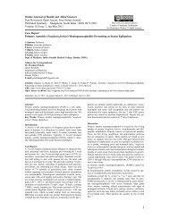
Figure 1.1<br />
Graphical representation of model neurones and their connections shown <strong>in</strong> an ad-hoc neural network. A neurone (#1)<br />
is<br />
<strong>in</strong>hibited (a subtraction) by another neurone which <strong>in</strong> its turn is <strong>in</strong>hibited by neurone #2: mutual <strong>in</strong>hibition. Neurone<br />
#2 projects onto neurone #4 through a shunt<strong>in</strong>g <strong>in</strong>hibition which causes the sum of the two excitatory <strong>in</strong>puts to be divided<br />
by the output of neurone #2. The excitatory <strong>in</strong>puts to #4 are gated (5) by the output of neurone #1, branch<strong>in</strong>g at (3). As<br />
a result the signal carried by the gated synapses activate neurone #4 only when the output of neurone #1 exceeds a certa<strong>in</strong><br />
level. F<strong>in</strong>ally, at (6), the output of neurone #4 is gated through shunt<strong>in</strong>g <strong>in</strong>hibition, divid<strong>in</strong>g it by the signal carried on the<br />
<strong>in</strong> neurone #7 by its second <strong>in</strong>put.<br />
with spontaneous, non-constant, output — a pacemaker neurone ? — <br />
(% ) <br />
gat<strong>in</strong>g synapse. This signal is then multiplied (<br />
)<br />
X<br />
7<br />
excites neurone #2. This summator neurone (<br />
)
1.3. AN OVERVIEW OF THIS THESIS 23<br />
Despite the compactness and rigour of this notation, the dedicated neural networks<br />
presented <strong>in</strong> the follow<strong>in</strong>g chapters are best represented graphically. In the graphical representation<br />
used throughout this thesis, neurones are represented as circles or "rounded<br />
boxes": see figure 1.1. Symbols <strong>in</strong>side the neurones <strong>in</strong>dicate their function: represents<br />
a summator neurone (an <strong>in</strong>terneurone), a % represents a neurone that divides one <strong>in</strong>put by<br />
another.<br />
Axons project<strong>in</strong>g from a neurone are represented by l<strong>in</strong>es. Despite the fact that most<br />
natural neurones seem to have only one axon, the graphical representation of neural networks<br />
benefits at times from allow<strong>in</strong>g multiple axons per soma. All axons project<strong>in</strong>g from a s<strong>in</strong>gle<br />
neurone carry the same signal. Output diverg<strong>in</strong>g to several target neurones is represented<br />
a <br />
either by multiple axons leav<strong>in</strong>g the cell, or by a branch<strong>in</strong>g axon. Axon branches carry the<br />
<br />
same signal as the ma<strong>in</strong> stem; they are represented by l<strong>in</strong>es attached with a small black dot<br />
to the ma<strong>in</strong> axon.<br />
Synapses are <strong>in</strong>dicated by end-symbols on the l<strong>in</strong>es represent<strong>in</strong>g axons. They can contact<br />
either the neurone’s cell body, or another synapse. The latter case <strong>in</strong>dicates some form of<br />
synaptic gat<strong>in</strong>g: the action of the gated synapse is altered <strong>in</strong> a way that depends on the type<br />
of gat<strong>in</strong>g synapse. Excitatory synapses are <strong>in</strong>dicated by arrows ), regular (subtract<strong>in</strong>g)<br />
<strong>in</strong>hibitory synapses by "T-arrows" (), and shunt<strong>in</strong>g <strong>in</strong>hibitory synapses by open circles<br />
().<br />
(<br />
1.3 An overview of this thesis<br />
Practice yourself, for heaven’s sake, <strong>in</strong> little th<strong>in</strong>gs; and thence proceed to greater<br />
Epictetus<br />
An <strong>in</strong>troduction to the research presented <strong>in</strong> this thesis will now be given. The goal of this<br />
research is to create a model of an animal <strong>in</strong> its environment. The model had to be a neuroethological<br />
one: it would have to be stated <strong>in</strong> terms of receptors, neurones, muscles and the<br />
body of the animal, and the <strong>in</strong>teractions between these components: a neuro-ethogram. The<br />
<strong>in</strong>teractions of the animal with its environment — sensory perceptions and motor actions —<br />
would have to be physically <strong>in</strong>spired. The whole ensemble would have to display life-like<br />
behaviour when simulated.<br />
What is the use of such an endeavour? Why, it is very reward<strong>in</strong>g <strong>in</strong>deed to create<br />
someth<strong>in</strong>g life-like — to play god. Personal rewards, however, are not the perfect means<br />
to raise funds for any project, unless they have a substantial overlap with hot topics <strong>in</strong><br />
fundamental research or (alas even better) applied sciences. Therefore, what is the use of<br />
such an endeavour?<br />
1.3.1 A hypothetical modell<strong>in</strong>g attempt<br />
Hippogriff, n.:<br />
An animal (now ext<strong>in</strong>ct) which was half horse and half griff<strong>in</strong>. The griff<strong>in</strong> was itself a<br />
compound creature, half lion and half eagle. The hippogriff was actually, therefore, only<br />
one quarter eagle, which is two dollars and fifty cents <strong>in</strong> gold. The study of zoology is full<br />
of surprises.<br />
Ambrose Bierce, The Devil’s Dictionary
24 CHAPTER 1. INTRODUCTION<br />
Ideally, one would consult the literature <strong>in</strong> order to f<strong>in</strong>d the complete ethogram of the<br />
desired animal, its neural wir<strong>in</strong>g scheme, the mechanical properties of its body and the<br />
environment it lives <strong>in</strong>, and the physical properties of its sensory systems. One could then<br />
proceed to port this model to a suitable simulation environment and simulate its behaviour<br />
at the desired level of detail: a siliclone.<br />
Let us suppose one could succeed <strong>in</strong> the specification of such a model. This would allow<br />
one to come up with the animal’s complete neuro-ethogram, the explanation of the animal’s<br />
behaviour <strong>in</strong> terms of the functional <strong>in</strong>teractions between its neurones, sensory systems, etc.<br />
One could question the droit d’existence of such a model. After all everyth<strong>in</strong>g was<br />
known? And what is the use of a model if it is just as complex as the orig<strong>in</strong>al? Both<br />
objections are true — to a certa<strong>in</strong> extent. Everyth<strong>in</strong>g was known, <strong>in</strong>deed, but only <strong>in</strong> a<br />
descriptive sense, without too much explicative power. And is the model as complex as<br />
the orig<strong>in</strong>al, ignor<strong>in</strong>g all details below the cellular level, which <strong>in</strong>clude the whole metabolic<br />
system of the animal?<br />
As with any explicative (as opposed to descriptive) k<strong>in</strong>d of model, predictions can be<br />
made based on simulated/simulation experiments. These predictions can take the form of<br />
previously unobserved behaviours. They can also take the form of predictions concern<strong>in</strong>g<br />
the function<strong>in</strong>g of the nervous system, e.g. as a result of necessary adjustments to the model<br />
<strong>in</strong> order to reproduce observed behaviour. All these predictions can be tested empirically,<br />
that is, <strong>in</strong> the real, natural, system.<br />
<strong>Of</strong> course this discussion is somewhat out of place. At present there is only one animal<br />
whose complete neural wir<strong>in</strong>g scheme is known: the nematode Caenorhabditis elegans,<br />
a roundworm approximately 30 cm long. Its nervous system consists of exactly (!) 302<br />
neurones, with some 7000 synapses (Niebur and Erdős 1993). In simulations of a model of<br />
the motor centre of the (ma<strong>in</strong>ly electrotonic) nervous system, Niebur and Erdős have been<br />
able to reproduce observed motor behaviour; expla<strong>in</strong><strong>in</strong>g it <strong>in</strong> terms of their realistic model<br />
properties (parameters). They could also state additional assumptions on how the real system<br />
works, given the <strong>in</strong>capability to reproduce certa<strong>in</strong> other observations with<strong>in</strong> physiologically<br />
plausible ranges of parameters.<br />
In all other <strong>animals</strong>, only bits and pieces of the nervous system are known from anatomical<br />
studies, or hypothesised based on electrophysiological and/or psychophysical 13studies.<br />
Therefore, the theoretical neuro-ethologist seek<strong>in</strong>g to compile the neuro-ethogram of, say, a<br />
fly, will have to use his own common sense to fill <strong>in</strong> the miss<strong>in</strong>g details <strong>in</strong> his model.<br />
If his common sense is adequately biologically <strong>in</strong>spired, the result<strong>in</strong>g model will have<br />
additional predictive power. After all, there is no reason why the parts of the model <strong>in</strong>vented<br />
by the modeller should be less plausible than those parts described <strong>in</strong> the literature. The latter<br />
are assumptions based on observations of the real system, while the former are probably<br />
based on observations of these observations. They are "compositions <strong>in</strong> the style of ...".<br />
Therefore the model animal will conta<strong>in</strong> predictions as to what k<strong>in</strong>d of neural structures one<br />
might look for <strong>in</strong> relation to what function <strong>in</strong> the natural animal models of the hypothetical<br />
animal. Also it can serve as a vehicle to test the both exist<strong>in</strong>g, empirically based; and the<br />
hypothesised neural structures <strong>in</strong> context.<br />
13 In electrophysiology direct, <strong>in</strong>tracellular or extracellular, record<strong>in</strong>gs are made of the transmembrane potential<br />
of one or several cells. This <strong>in</strong>cludes action potentials; spikes. Us<strong>in</strong>g multiple electrodes it is possible<br />
to reconstruct the path taken by a given flow of <strong>in</strong>formation. In psychophysics one measures the response of<br />
the <strong>in</strong>tact animal to certa<strong>in</strong> stimuli. Aga<strong>in</strong> it is possible to <strong>in</strong>fer the properties, and ultimately possibly wir<strong>in</strong>g<br />
schemes, of the nervous systems <strong>in</strong>volved <strong>in</strong> the given task based on the observed results.
1.3. AN OVERVIEW OF THIS THESIS 25<br />
Summaris<strong>in</strong>g, an attempt to construct a neuro-ethological model of an animal <strong>in</strong> its environment<br />
has the follow<strong>in</strong>g droits d’existence:<br />
1. It allows exist<strong>in</strong>g theories, hypothesises and explanations giv<strong>in</strong>g possible neuronal<br />
implementations of functions related to one or several of the simulated behaviours<br />
to be tested <strong>in</strong> the context of a behav<strong>in</strong>g animal. These tests are not restricted to the<br />
limited range of controlled conditions atta<strong>in</strong>able <strong>in</strong> the laboratory. Nor is one restricted<br />
to test<strong>in</strong>g just the transition function of the systems <strong>in</strong> question. A system implement<strong>in</strong>g<br />
e.g. a form of Weber adaptation could be modelled with a black box with the property<br />
, which is the Weber law stat<strong>in</strong>g that some just noticeable difference (JND)<br />
is<br />
proportional to the overall level. Rather, by us<strong>in</strong>g a possible neural implementation<br />
of the system, one <strong>in</strong>troduces dynamics and possible deviations from the idealised<br />
transition function. Both aspects can result <strong>in</strong> side-effects that cause and/or expla<strong>in</strong><br />
otherwise unobserved, life-like behavioural details.<br />
<br />
2. It calls for the generation of new hypothetical neuronal implementations for functions<br />
that have not been described <strong>in</strong> the literature. In other words, the hypothetical animal<br />
can become a model for real <strong>animals</strong>. Both the "old" and the "new" hypothetical neural<br />
structures can, when simulated, result <strong>in</strong> predictions that can be tested <strong>in</strong> the real<br />
animal.<br />
3. Creat<strong>in</strong>g neuro-ethological designs of novel neural structures, and tun<strong>in</strong>g all the parameters<br />
<strong>in</strong> the complete model to let it behave <strong>in</strong> a life-like fashion, one gets a very<br />
good idea of the problems that organisms encounter <strong>in</strong> every day circumstances, and<br />
<strong>in</strong> evolutionary context.<br />
4. It can serve as a substrate for simulated evolution. In nature evolution of novel<br />
behaviours (i.e. novel neuro-ethological structures) is probably based upon the modification<br />
and/or duplication (the evolution...) of exist<strong>in</strong>g neuro-ethological structures.<br />
After all it seems more plausible to assume that some new structure evolves out of another,<br />
exist<strong>in</strong>g, structure, than assum<strong>in</strong>g that it just "arrives" 14.This same process can<br />
be applied to a neuro-ethological model. One can thus start with a very simple neuroethogram<br />
conta<strong>in</strong><strong>in</strong>g only the basic necessities for survival. This neuro-ethogram can<br />
then gradually be extended to <strong>in</strong>clude more and more higher order behaviours. In<br />
this way one circumvents the "plunge-<strong>in</strong>-the-deep" effect of start<strong>in</strong>g with a complete<br />
neuro-ethogram, and then work<strong>in</strong>g top-down <strong>in</strong> order to comprehend it. An additional<br />
bonus is the fact that the model’s evolv<strong>in</strong>g complexity, by follow<strong>in</strong>g a course<br />
likely to be similar to the course of natural evolution, endows the model with similar<br />
advantages: adaptability, robustness and evolvability.<br />
5. It is possible to shift the focus of the studied model from a purely biological to a more<br />
applied po<strong>in</strong>t of view. Given the fact that the model is specified <strong>in</strong> terms of <strong>in</strong>teractions<br />
between functional elements, and conta<strong>in</strong>s a physically plausible <strong>in</strong>teraction with the<br />
environment, one can transform the model of an animal <strong>in</strong>to the model of a robot with<br />
only very m<strong>in</strong>or modifications. This robot model should be easily transportable to a<br />
hardware implementation, given the manner <strong>in</strong> which it is specified.<br />
14 This notion is explored <strong>in</strong> somewhat more detail <strong>in</strong> chapter 6.
26 CHAPTER 1. INTRODUCTION<br />
1.3.2 A more realistic modell<strong>in</strong>g attempt: of <strong>paddlers</strong> and glowballs<br />
Let us now, f<strong>in</strong>ally, turn to the subject of this thesis. As stated earlier, the goal of the study<br />
presented is to create a neuro-ethological model of an animal <strong>in</strong> its environment. First, let us<br />
take a look at the ethogram of the modelled animal.<br />
S<strong>in</strong>ce we are start<strong>in</strong>g from scrap, beg<strong>in</strong>n<strong>in</strong>g at the basics, we must choose a simple<br />
ethogram, a sensori-motor task, which is necessary for bare survival. If one observes <strong>animals</strong>,<br />
one can easily come to the conclusion that the "simpler" the animal, the more no-nonsense its<br />
behaviour. Simple <strong>animals</strong> like <strong>in</strong>sects seem to be busy do<strong>in</strong>g someth<strong>in</strong>g useful most of the<br />
time: always <strong>in</strong> search of someth<strong>in</strong>g. Someth<strong>in</strong>g can be either food or a partner, two goals<br />
that are directly l<strong>in</strong>ked to survival.<br />
In other words, navigation is a crucial, basic, behaviour. It seems safe to conjecture that<br />
many other, more complex, behaviours evolved to <strong>in</strong>crease the efficiency of that one, basic<br />
behaviour. More generally, they evolved to <strong>in</strong>crease the efficiency with which food or mates<br />
can be found — or danger escaped.<br />
Navigation is therefore the behaviour of choice <strong>in</strong> this study. To elim<strong>in</strong>ate the complications<br />
posed by f<strong>in</strong>d<strong>in</strong>g mates and <strong>in</strong>teract<strong>in</strong>g with them, only fourag<strong>in</strong>g, the process<br />
of f<strong>in</strong>d<strong>in</strong>g food, is considered. <strong>Of</strong> course the same system can be used to f<strong>in</strong>d both food<br />
and mates. Once a mate is found, however, some form of <strong>in</strong>teraction (<strong>in</strong> addition to just<br />
devour<strong>in</strong>g the <strong>in</strong>teract<strong>in</strong>g partner, although that does belong to sexual <strong>in</strong>teraction <strong>in</strong> some<br />
animal species..) should take place. The neuro-ethogram of sexual <strong>in</strong>teraction would be fit<br />
for another thesis...<br />
1.3.2 a Introduc<strong>in</strong>g: the paddler<br />
A neuro-ethological model of a fourag<strong>in</strong>g animal requires a model of a sensory-motor system.<br />
This model should <strong>in</strong>clude descriptions of the sensory systems, the (central) nervous<br />
systems and the motor systems used. Also, as mentioned before, some physically plausible<br />
description of the <strong>in</strong>teractions between the animal and its environment should be part of the<br />
model.<br />
The physical description of the animal’s <strong>in</strong>teraction with its environment (locomotion) is<br />
seldomly simple. There is a substantial literature on this topic, both on the neural control<br />
(generation) and the mechanical aspects, but not necessarily <strong>in</strong> the same animal. The literature<br />
deales <strong>in</strong> particular with fishes’ swimm<strong>in</strong>g, flight of birds and <strong>in</strong>sects, and quadruped<br />
and hexapod locomotion. The latter two forms of locomotion are quite complex <strong>in</strong> both their<br />
nervous control and physical description. Swimm<strong>in</strong>g <strong>in</strong> fish <strong>in</strong>volves the hydrodynamics of<br />
non-lam<strong>in</strong>ar (turbulent) flows <strong>in</strong> all but the slowest swimmers.<br />
To circumvent these problems, a model of an animal was designed from scrap. It is not<br />
a model of any exist<strong>in</strong>g animal. Rather it is <strong>in</strong>tended to be a model of an animal as it might<br />
exist or have existed. As such it is immune to critiques such as "But we know that <strong>in</strong> the real<br />
animal...".<br />
Modell<strong>in</strong>g a hypothetical animal also allows one to start with the simplest scenario<br />
possible. One can more or less follow the same course as evolution probably did. That<br />
is why the birthplace of our hypothetical animal is <strong>in</strong> the deep-sea: a very quiet place,<br />
devoid of nasty fluctuations and distract<strong>in</strong>g stimuli. The only visual stimulation comes<br />
from autolum<strong>in</strong>escent organisms, volcanoes, and the occasional remote controlled deep-sea<br />
vehicle. Locomotion <strong>in</strong> this medium can be very simple too.
1.3. AN OVERVIEW OF THIS THESIS 27<br />
In this milieu a visual predator evolved long before the arrival of deep sea vehicles: the<br />
archepaddler, ancestor of the genus of the Hypo<strong>paddlers</strong>: hypothetical <strong>animals</strong> that paddle<br />
under (hypo) the ocean’s surface. It is endowed with a pair of primitive compound eyes,<br />
a pair of f<strong>in</strong>s — paddles — that generate the necessary thrust. A simple central nervous<br />
system converts the responses of the eyes <strong>in</strong>to appropriate paddl<strong>in</strong>g (swim) commands. The<br />
paddler’s body is disk-like, with a snout <strong>in</strong> front, a pair of pectoral f<strong>in</strong>s for vertical stability<br />
(lift control), and a stiff tailf<strong>in</strong> for course stability. This simple body geometry comb<strong>in</strong>ed<br />
with the low swimm<strong>in</strong>g velocity, allows the paddler’s motion to be approximated by a set<br />
of differential equations describ<strong>in</strong>g the motion of a solid body <strong>in</strong> a lam<strong>in</strong>ar medium. Thus<br />
the problem of the <strong>in</strong>tractability of the swimm<strong>in</strong>g, walk<strong>in</strong>g and fly<strong>in</strong>g of more advanced<br />
creatures can be elim<strong>in</strong>ated.<br />
The scenario is completed by <strong>in</strong>troduc<strong>in</strong>g the paddler’s prey of choice: the glowball.<br />
Glowballs are small, bentopelagic 15, autolum<strong>in</strong>escent <strong>animals</strong>. They emit light of a frequency<br />
to which the paddler’s eyes are tuned optimally. When fourag<strong>in</strong>g, the paddler keeps<br />
its snout open, and scoops up the glowballs it encounters on its path. Chapter 2 elaborates<br />
on the archepaddler, among others illustrat<strong>in</strong>g the effect of smart geometrical design of the<br />
paddler’s body.<br />
1.3.3 A snapshot of the paddler’s evolution<br />
Dur<strong>in</strong>g the course of evolution, the paddler’s habitat gradually shifted towards shallower<br />
waters. In these sunlit waters a huge problem for a visual predator prey<strong>in</strong>g on autolum<strong>in</strong>iscent<br />
prey announced itself: background illum<strong>in</strong>ation. Imag<strong>in</strong>e the "confusion" of an animal<br />
that uses light as an <strong>in</strong>dication that prey is present! It shall be clear that a solution, an evolution<br />
of the visual system, had to be found. And <strong>in</strong>deed, a solution was found, as described<br />
<strong>in</strong> chapter 3, where a light-adapt<strong>in</strong>g ret<strong>in</strong>a will be discussed. The mach<strong>in</strong>ery <strong>in</strong> this ret<strong>in</strong>a<br />
conta<strong>in</strong>s a form of Weber adaptation (adaptation obey<strong>in</strong>g the Weber law described above),<br />
and a high-pass filter.<br />
It is nice to note here that the high-pass filter <strong>in</strong> the ret<strong>in</strong>a was not designed as a highpass<br />
filter, nor as a model of a particular biological system. It was merely <strong>in</strong>tended to be a<br />
clever mechanism to encode changes <strong>in</strong> the ret<strong>in</strong>al <strong>in</strong>put relative to the average <strong>in</strong>put over<br />
a certa<strong>in</strong> time w<strong>in</strong>dow. It evolved from a simpler mechanism that shared parts with the<br />
Weber mach<strong>in</strong>e (i.e. the leaky <strong>in</strong>tegrator of the Weber mach<strong>in</strong>e; see chapter 3). The "mature"<br />
mechanism later turned out to be 1 formally identical to a high-pass filter, and 2 highly<br />
similar <strong>in</strong> function to a particular ganglion cell, the LMC cell, <strong>in</strong> the fly’s ret<strong>in</strong>a.<br />
In chapters 4 and 5 a side step is made to the motor parts of the model. It has been said<br />
that the paddler swims by means of two paddles. These paddles are moved <strong>in</strong> a rhytmic, updown,<br />
manner to <strong>in</strong>duce thrust. The swim command from the nervous system, however, is<br />
a signal that specifies the momentarily required amount of thrust, and thus does not conta<strong>in</strong><br />
the necessary oscillations to drive the paddles directly.<br />
<br />
The peripheral nervous system conta<strong>in</strong>s a pair of paddle controllers that convert the swim<br />
command <strong>in</strong> muscle commands for the paddles’ antagonistic muscles. A feedback control<br />
system ensures that a given swim command results <strong>in</strong> the correspond<strong>in</strong>g paddle movement<br />
as soon as possible. The design of these nervous structures is discussed <strong>in</strong> detail <strong>in</strong> chapter<br />
4.<br />
The paddler is an animal with a certa<strong>in</strong> amount of mass. S<strong>in</strong>ce mass, <strong>in</strong>ertia and sluggish-<br />
15 Liv<strong>in</strong>g just above the seafloor, to which they are attached through a short tether.
28 CHAPTER 1. INTRODUCTION<br />
ness are synonyms, it will be clear that there can be a substantial amount of time between the<br />
moment a swim command was given, and the moment the correspond<strong>in</strong>g swimm<strong>in</strong>g speed<br />
is atta<strong>in</strong>ed. Too much delay is not desirable, s<strong>in</strong>ce it can <strong>in</strong>terfere seriously with the paddler’s<br />
manouevrability, especially at low speeds (a characteristic of the equations govern<strong>in</strong>g the<br />
paddler’s motion).<br />
To overcome this problem, the paddler’s motor system conta<strong>in</strong>s another control system:<br />
the speed control system. This system, discussed <strong>in</strong> detail <strong>in</strong> chapter 5, compares the<br />
paddler’s actual speed (relative to the water) with the desired speed. If necessary it adjusts<br />
the ga<strong>in</strong> of the projection of the swim command to the paddle controllers and/or <strong>in</strong>creases<br />
the total frontal area, by tilt<strong>in</strong>g the pectoral f<strong>in</strong>s. Thus the paddler can actively (though<br />
unconsciously) <strong>in</strong>crease its swimm<strong>in</strong>g effort to compensate for low speeds; it can passively<br />
decrease its speed by "water-brak<strong>in</strong>g" with its pectoral f<strong>in</strong>s.<br />
Chapter 6 aga<strong>in</strong> focusses on the paddler’s visual system. The evolution of the visual<br />
system discussed <strong>in</strong> this chapter was prompted by the appearance of smarter glowballs.<br />
These glowballs are no longer bentopelagic, but have <strong>in</strong>creased their chances of survival by<br />
actively roam<strong>in</strong>g about. This <strong>in</strong>creases their chances of escape from hungry <strong>paddlers</strong>, but<br />
also <strong>in</strong>creases their own food <strong>in</strong>take.<br />
In response to these developments, the <strong>paddlers</strong>’ visual system learned to detect the<br />
motion of objects relative to itself: whether they approach or threaten to escape. The same<br />
novelty, the motion detection system, allows the paddler to <strong>in</strong>crease its manouevrability,<br />
and to fixate and track objects. It makes use of the movement of objects’ images across<br />
the ret<strong>in</strong>a. From this <strong>in</strong>ternal <strong>in</strong>formation, the so-called optic flow, a substantial amount of<br />
<strong>in</strong>formation concern<strong>in</strong>g the relations <strong>in</strong> and to the external world can be extracted. In the<br />
example presented <strong>in</strong> chapter 6, the crucial use of the optic flow is the detection of glowballs<br />
that threaten to escape. The motion detection system allows the paddler to speed up to catch<br />
those glowballs.<br />
1.3.3 a Results<br />
The previous section presented a bird’s eye view of the different topics discussed <strong>in</strong> this<br />
thesis. At this po<strong>in</strong>t it seems useful to give a little <strong>in</strong>troduction to the results. In a modell<strong>in</strong>g<br />
study like this, there are actually two k<strong>in</strong>ds of results. The second of these will be familiar<br />
to empirical researchers. These are results, data, that can (and will) be presented <strong>in</strong> graphs.<br />
They result from experiments done with/on the model. Mostly they will present the effect<br />
on some observable of vary<strong>in</strong>g some parameter, while co-vary<strong>in</strong>g some other parameter(s).<br />
The first k<strong>in</strong>d of results will generally not be evidently a result. They are <strong>in</strong> fact the<br />
different parts of the model. As such, they are presented as facts; model descriptions<br />
(schematic draw<strong>in</strong>gs) that work, and will be studied empirically.<br />
The evolutionary history of these model parts, the road taken to end up at the f<strong>in</strong>al descriptions,<br />
will mostly not enter the discussion, ma<strong>in</strong>ly to prevent excessive page numbers.<br />
Sometimes, when the road was especially long and/or difficult, as <strong>in</strong> chapter 4, an exeption<br />
has been made <strong>in</strong> an attempt to communicate someth<strong>in</strong>g of the difficulties that were<br />
encountered.
1.3. AN OVERVIEW OF THIS THESIS 29<br />
There are no facts, only <strong>in</strong>terpretations<br />
F. Nietzsche, 1901<br />
Everyth<strong>in</strong>g should be made as simple as possible, but not simpler<br />
Albert E<strong>in</strong>ste<strong>in</strong><br />
1.3.4 Some conclusions<br />
The research presented <strong>in</strong> this thesis is hardly f<strong>in</strong>ished. On the contrary, it is of a highly<br />
exploratory nature, and as such it can be extended <strong>in</strong> many many ways. The paddler <strong>in</strong><br />
its present <strong>in</strong>carnation is still <strong>in</strong> the early stages of its development; it has a very long<br />
evolutionary road ahead. It seems likely that, just like the system be<strong>in</strong>g modelled, the<br />
paddler and its habitat can be evolved <strong>in</strong>def<strong>in</strong>itely.<br />
Due to the exploratory character of the research, and due to its "open end", it is impossible<br />
to draw one or a few f<strong>in</strong>al conclusions captur<strong>in</strong>g the whole essence of the work. One<br />
can, however, very well draw conclusions regard<strong>in</strong>g the solution of various <strong>in</strong>terest<strong>in</strong>g<br />
subproblems of survival <strong>in</strong> a chang<strong>in</strong>g environment.<br />
Toutes les généralisations sont dangereuses. Même celle-ci<br />
Alexandre Dumas, fils<br />
1.3.4 a Guidel<strong>in</strong>es for the modeller<br />
It is possible to extract some useful conclusions from the present state of the research.<br />
First there is what might be called the compensation pr<strong>in</strong>ciple. This pr<strong>in</strong>ciple holds that<br />
there is not one, nor a few, optimal comb<strong>in</strong>ation(s) of characteristics (parameters), but rather a<br />
whole range. With<strong>in</strong> this range, ill effects of a change <strong>in</strong> one parameter can be compensated<br />
for by chang<strong>in</strong>g another parameter that affects the same properties. Over the whole range,<br />
adequate behaviour results.<br />
This pr<strong>in</strong>ciple has been observed ma<strong>in</strong>ly <strong>in</strong> the parameters specify<strong>in</strong>g the paddler’s<br />
geometrical properties: see chapter 2. One example is the relation between the <strong>in</strong>ter-ocular<br />
and the <strong>in</strong>ter-paddle distances. In an animal that uses <strong>in</strong>ter-ocular eye-response differences<br />
to determ<strong>in</strong>e directions, a larger <strong>in</strong>ter-ocular distance can result <strong>in</strong> a higher directional<br />
sensitivity. A smaller <strong>in</strong>ter-paddle distance causes the paddler to be less capable to turn fast.<br />
These effects can cancel each other out.<br />
A second example comes from a small excursion not described <strong>in</strong> the follow<strong>in</strong>g text.<br />
The excursion <strong>in</strong>volved a related paddler species, sport<strong>in</strong>g two pairs of paddles, both pairs<br />
receiv<strong>in</strong>g the same swim commands. The paddles of a paddler are fully specified by two<br />
parameters: their position on the body, and the direction <strong>in</strong> which they po<strong>in</strong>t. In a twopaddle<br />
paddler, there is a rather large range of comb<strong>in</strong>ations of these parameters for which the<br />
paddler fourages optimally. In a four-paddle paddler one f<strong>in</strong>ds two separate, slightly smaller<br />
ranges of comb<strong>in</strong>ations of these parameters. These two ranges reflect the specialisation of<br />
either the front or the rear paddle pair to steer<strong>in</strong>g paddles, with the other pair tak<strong>in</strong>g care<br />
ma<strong>in</strong>ly of forward locomotion.
30 CHAPTER 1. INTRODUCTION<br />
Second there is the importance of embedd<strong>in</strong>g physically <strong>in</strong>spired dynamics <strong>in</strong> the model.<br />
Such more or less realistic dynamics can enrich the behaviour displayed by the model. They<br />
can also allow simple solutions to certa<strong>in</strong> problems; solutions, smart mechanisms, that make<br />
clever use of the physical properties of the system.<br />
An example of the latter reason is given <strong>in</strong> chapter 5. In this chapter a speed control<br />
system is described that is <strong>in</strong>tended to match the paddler’s actual speed to its <strong>in</strong>tended<br />
speed. Here the problem arises how to compare measured ego-speed with the <strong>in</strong>tended egospeed<br />
that corresponds to the current swim commands. Ego-speed is measured through the<br />
drag excerted on a hair receptor by the water flow around the paddler’s body. This drag is<br />
subject to the same equations govern<strong>in</strong>g the drag experienced by the whole paddler, and thus<br />
the paddler’s speed. In short: the paddler’s speed is proportional to the square root of the<br />
thrust it generates; the ego-speed measurement is proportional to the square of the speed.<br />
The speed control system therefore only needs to know or learn the speed measurement<br />
correspond<strong>in</strong>g to a given set of swim commands. Assum<strong>in</strong>g that the generated thrust is<br />
proportional to the swim command, it can then directly "compute" a corrective ga<strong>in</strong> factor<br />
on the basis of measured and expected speed.<br />
How physically <strong>in</strong>spired dynamics can enrich the behaviour of a model can be illustrated<br />
with the light-adapt<strong>in</strong>g mach<strong>in</strong>ery of the diurnal paddler’s ret<strong>in</strong>a. Part of this mach<strong>in</strong>ery<br />
is a differentiator; not the mathematical beast 16,but a "leaky differentiator": a high-pass<br />
filter. Such a filter can be constructed by subtract<strong>in</strong>g from an <strong>in</strong>put a time-averaged copy<br />
of the same <strong>in</strong>put: the output of a leaky <strong>in</strong>tegrator or low-pass filter. If the high-pass filter<br />
is to output its signal as a spike frequency, the choice for two output channels — ON and<br />
OFF — is a logical one. These channels can then be assigned different weights <strong>in</strong> subsequent<br />
process<strong>in</strong>g.<br />
The leaky <strong>in</strong>tegrator <strong>in</strong>corporated <strong>in</strong> the high-pass filter <strong>in</strong>troduces a subtle difference between<br />
this leaky differentiator, and its pure, mathematical, counterpart. Due to the memory<br />
<strong>in</strong> the leaky <strong>in</strong>tegrator, changes <strong>in</strong> <strong>in</strong>put are signalled for a much longer time: the response<br />
becomes phasic-tonic. In case of <strong>in</strong>crease of <strong>in</strong>put — e.g. after someth<strong>in</strong>g appears <strong>in</strong> the field<br />
of view — this only means that the presence of some object is signalled a little longer. When<br />
someth<strong>in</strong>g disappears (an <strong>in</strong>put drop to zero), after-images occur, which can mislead the<br />
paddler <strong>in</strong>to assum<strong>in</strong>g prey where there is none.<br />
Paddlers that use the OFF channel <strong>in</strong> their light-adapt<strong>in</strong>g mach<strong>in</strong>ery show a phenomenon<br />
also known to occur <strong>in</strong> Planaria (F. Verheijen, personal communication): edge follow<strong>in</strong>g,<br />
<strong>in</strong> which a steep gradient of (background) illum<strong>in</strong>ation is traced. This behaviour can be<br />
expla<strong>in</strong>ed by the equal importance of enter<strong>in</strong>g or leav<strong>in</strong>g a light or dark zone. As a result<br />
the paddler will return to the lighted region that the last of its two eyes just left, just as it will<br />
turn back toward the dark zone when the last of its eyes has entered the lighted region. The<br />
result: a paddler wiggl<strong>in</strong>g along the border between light and dark.<br />
This leads to the third observation, the importance of the use of non-idealised components.<br />
It will be clear that no biological system <strong>in</strong>corporates ideal components: neither neurones,<br />
nor <strong>in</strong> sensory systems, nor <strong>in</strong> motor systems. Yet these non-ideal components are comb<strong>in</strong>ed<br />
<strong>in</strong> such smart ways that the <strong>in</strong>tegrated (sub)systems are remarkably sensitive and robust.<br />
Part of the fun of neuro-ethological modell<strong>in</strong>g lies <strong>in</strong> try<strong>in</strong>g to reproduce the ideal by us<strong>in</strong>g<br />
non-ideal components, just as <strong>in</strong> nature.<br />
One need not always try, however, to go for an ideal (sub)system. This is illustrated by the<br />
paddler’s motion detection system discussed <strong>in</strong> chapter 6. The elementary motion detector<br />
16 Mathematician’s comment: "I didn’t know it was a beast. But then I’m not a biologist..."
1.3. AN OVERVIEW OF THIS THESIS 31<br />
(EMD) — measur<strong>in</strong>g local image-motion across the ret<strong>in</strong>a — is based on a model of the fly’s<br />
EMD. In this fly’s model the outputs of two subunits sensitive to two opposite directions are<br />
subtracted to yield a s<strong>in</strong>gle signal, encod<strong>in</strong>g both the direction and speed 17.This subtraction<br />
also reduces alias<strong>in</strong>g; the <strong>in</strong>correct signall<strong>in</strong>g of motion or direction of motion. It turns out<br />
that the paddler’s systems that make use of the EMD outputs benefit from the larger output<br />
from EMDs <strong>in</strong> the situation without subtraction. The larger output (the EMDs are more often<br />
more active) outweighs the apparent disadvantage of the large fraction of <strong>in</strong>correct EMD<br />
responses.<br />
<br />
17 Each EMD is sensitive to just a small range of velocities — or rather, temporal frequencies; see chapter 6.<br />
An active EMD thus signals a given very limited range of image-motions, at a given location; the strength of its<br />
signal encodes both the direction of motion, and the EMDs "confidence".
32 CHAPTER 1. INTRODUCTION
<strong>Hypothetical</strong> visually-guided<br />
<strong>animals</strong><br />
Submitted for Publication.<br />
33
34 CHAPTER 2. HYPOTHETICAL VISUALLY-GUIDED ANIMALS<br />
2.1 Introduction<br />
The explosive growth of modern neuroscience has made it feasible to study classical problems<br />
of bra<strong>in</strong> and behaviour with new vigour and more rigour. The <strong>in</strong>creas<strong>in</strong>g computational<br />
power of easily accessible computers makes it possible to formulate models of e.g. bra<strong>in</strong> and<br />
behaviour that are so complex that they can only be studied by simulation.<br />
In modell<strong>in</strong>g behaviour, the importance of the relations between the animal’s habitat<br />
(i.e. the environment it lives <strong>in</strong>) and the animal’s behavioural repertoire should be recognised.<br />
Models of behaviour ideally <strong>in</strong>clude an explicit attempt to model the habitat and the<br />
<strong>in</strong>teractions between the modelled animal and its habitat.<br />
Observ<strong>in</strong>g the "law of uphill analysis and downhill synthesis" (Braitenberg 1984), the<br />
animal model should be stated <strong>in</strong> simple terms, follow<strong>in</strong>g a bottom-up approach. Simple <strong>in</strong><br />
this case should be read as simple with respect to function. The biological structures (e.g.<br />
neural networks) which might implement this function have a habit of quickly assum<strong>in</strong>g a<br />
rather complex appearance. Simple systems can — by their <strong>in</strong>teractions — exhibit behaviour<br />
of a much higher level of complexity than their own behaviour. We are after a better<br />
understand<strong>in</strong>g of how this emergent complexity arises.<br />
Models for animal behaviour can roughly be divided <strong>in</strong>to two classes, purely symbolic<br />
(mathematical, algorithmic) versus biophysical/neuronal or bra<strong>in</strong> program (van de Gr<strong>in</strong>d<br />
1990, Beer 1990) approaches. Both classes of models have been implemented <strong>in</strong> hardware<br />
(see e.g. Pichon, Blanes & Francesch<strong>in</strong>i 1989, Brooks 1991). A drawback of purely symbolic<br />
representations (as described <strong>in</strong> e.g. Hogeweg 1991, Travers 1991, Coderre 1991, or M<strong>in</strong>sky<br />
1985) is that they bypass a number of "real-world" problems that are very relevant from a<br />
biological po<strong>in</strong>t of view. In our approach the animal – world <strong>in</strong>teractions, <strong>in</strong>clud<strong>in</strong>g physical<br />
aspects of sensory perception and locomotion, are made explicit as far as is feasible. Note<br />
that hardware implementations may well benefit from this approach: <strong>in</strong> simple tasks the<br />
hard part is not so much to decide what to do given certa<strong>in</strong> knowledge, but rather to extract<br />
this knowledge from the sensory <strong>in</strong>formation stream, and how to carry out desirecd actions.<br />
In addition to central (nervous) <strong>in</strong>telligence, natural <strong>animals</strong> also rely to a substantial<br />
amount on body-<strong>in</strong>telligence: their smart anatomical design and control systems can greatly<br />
enhance the usefulness of the various components. Therefore biophysical descriptions are<br />
<strong>in</strong>cluded of a (possibly m<strong>in</strong>imal) set of actions needed for <strong>in</strong>dividual survival and reproduction,<br />
layed down <strong>in</strong> the comb<strong>in</strong>ation of body form, body structure, environmental properties<br />
and the more or less malleable (’plastic’) local neuronal network structures (van de Gr<strong>in</strong>d<br />
1990).<br />
In simple organisms navigation is important <strong>in</strong> almost all aspects of survival: avoidance<br />
of predators and adverse environments, fourag<strong>in</strong>g and f<strong>in</strong>d<strong>in</strong>g partners. It therefore seemed<br />
appropriate to turn our attention to navigation of simple <strong>animals</strong>.<br />
The ma<strong>in</strong> object of the study here presented is a hypothetical animal called paddler. It<br />
is a very simple animal imag<strong>in</strong>ed to be liv<strong>in</strong>g <strong>in</strong> the deep sea. In such an environment<br />
there are hardly any irrelevant or redundant stimuli; the "atmospheric conditions" are all<br />
very constant. The animal has a roughly circular body which is bilaterally symmetric. It<br />
possesses two frontally placed eyes which measure aspects of the lum<strong>in</strong>ance distribution <strong>in</strong><br />
their visual field, and two paddles at the rear, which take care of locomotion. The animal<br />
is named for its characteristic, paddl<strong>in</strong>g movements. A central neural network converts<br />
the eye-responses <strong>in</strong>to left and right swim commands, both of which are projected onto the<br />
muscles controll<strong>in</strong>g the paddles. Steer<strong>in</strong>g is accomplished by a differential driv<strong>in</strong>g of the<br />
paddles, comb<strong>in</strong>ed with rotational drag caused by a stiff tailf<strong>in</strong> and the <strong>in</strong>ner (i.e. with
2.2. THE ANIMALS AND THEIR HABITAT 35<br />
respect to the turn<strong>in</strong>g direction) paddles.<br />
Paddlers are predators: they spend their time hunt<strong>in</strong>g for their specific prey: glowballs.<br />
These glowballs, globular, sessile or very slowly mov<strong>in</strong>g <strong>animals</strong> of vary<strong>in</strong>g radius, emit light<br />
of a wavelength to which the photopigment <strong>in</strong> the eyes of the paddler is highly sensitive.<br />
After hav<strong>in</strong>g detected a glowball, a hungry paddler orients towards it, and eats it as soon as<br />
its snout comes <strong>in</strong>to contact with the prey.<br />
Behav<strong>in</strong>g accord<strong>in</strong>g to this fairly simple ethogram, the energy reserve of the <strong>animals</strong> is<br />
repleted or depleted, depend<strong>in</strong>g on how many glowballs, and of which size, they eat; and<br />
how long a distance it takes them to get from one glowball to the next one. <strong>Of</strong> course,<br />
many different elaborations on this scheme are possible, such as reproductive behaviour,<br />
and a "rest-mode" (where the animal chooses a region to dwell <strong>in</strong> as long as it is sufficiently<br />
satiated). However, the vegetative physiology of <strong>paddlers</strong> will not be treated <strong>in</strong> this paper.<br />
We present a quantitative study of the <strong>in</strong>fluence of a number of parameters relat<strong>in</strong>g to<br />
morphological and physiological properties of the paddler on its ability to survive <strong>in</strong> a simple<br />
habitat. These parameters have been varied systematically, and the result<strong>in</strong>g performance<br />
of the paddler has been studied <strong>in</strong> relation to the values of other related parameters and<br />
behavioural capabilities like e.g. turn<strong>in</strong>g capability and speed. We have constra<strong>in</strong>ed ourselves<br />
to parameters related to the visuomotor aspects of paddler navigation and its nervous<br />
control.<br />
2.2 The <strong>animals</strong> and their habitat<br />
2.2.1 The paddler’s anatomy<br />
Without much loss of generality one can say that the paddler fourages <strong>in</strong> the th<strong>in</strong> layer near<br />
the bottom of the deep sea <strong>in</strong> which its prey lives. They can thus be regarded as 2D <strong>animals</strong><br />
<strong>in</strong> a flatland. In other words, we assume for the purpose of this chapter that the control<br />
system that regulates buoyancy (i.e. the animal’s vertical position) works adequately. Let us<br />
first turn to the eyes.<br />
The paddler possesses two eyes, positioned laterally at a certa<strong>in</strong> angle to the midsaggital<br />
plane of the animal (; see figure 2.1). angle The of the eye-axis relative to a plane pass<strong>in</strong>g<br />
through the nodal po<strong>in</strong>t of the eye, and parallel to the midsaggital plane, determ<strong>in</strong>es the<br />
central visual direction relative to the direction of the long body axis; it is <strong>in</strong>dependant of<br />
. The visual field of view spans an angle () symmetric around the eye-axis. These three<br />
angles and) might leave a bl<strong>in</strong>d region <strong>in</strong> front of the mouth of the paddler; <strong>in</strong> the<br />
"average" paddler, this region is filled with the touch-sensitive snout, under which the mouth<br />
can be found.<br />
)<br />
(,<br />
The eyes have <strong>in</strong> their ret<strong>in</strong>a a number (<br />
of receptive fields, which <strong>in</strong> this paper are<br />
s<strong>in</strong>gle photoreceptors (figure 2.2). Each of these receptive fields samples a certa<strong>in</strong> portion of<br />
the visual field with a given sensitivity. The sensitivity profile of the eye as formed by all<br />
receptive fields is taken to be gaussian. The direction of maximum sensitivity is at an angle<br />
relative to the direction of the eye-axis. Due to the different sensitivities of the receptors,<br />
the eye is <strong>in</strong>herently capable of dist<strong>in</strong>guish<strong>in</strong>g between far-off and closeby glowballs of the<br />
same size and radius (figure 2.2); the gaussian sensitivity profile also gives it a directional<br />
selectivity.<br />
However the simple paddler studied here (the archepaddler) does not yet use all the
36 CHAPTER 2. HYPOTHETICAL VISUALLY-GUIDED ANIMALS<br />
ρ<br />
tailf<strong>in</strong> r<br />
paddle<br />
δ<br />
α<br />
κ<br />
lefteye uniocular field<br />
β<br />
snout<br />
<br />
ϕ<br />
bl<strong>in</strong>d region<br />
b<strong>in</strong>ocular field<br />
"nose"<br />
visual distance Dv<br />
Figure 2.1<br />
The appearance of the archepaddler. The <strong>in</strong>dicated parameters are expla<strong>in</strong>ed <strong>in</strong> the text.<br />
<strong>in</strong>formation on the spatiotemporal light distribution that can potentially be encoded by an<br />
eye with a ret<strong>in</strong>a like this. Each of the two elementary eyes of this most primitive paddler<br />
possesses only two ganglion-cells that signal average receptor responses to the nervous<br />
system. One of those ganglion cells averages responses of the complete receptor pool — the<br />
total eye response. The other ganglion cell averages the responses of all active receptors <strong>in</strong><br />
the b<strong>in</strong>ocular field, a subset of the receptor pool that sample the directions sampled by both<br />
eyes.<br />
The nervous system is a very simple one: its only function is the process<strong>in</strong>g of visual<br />
<strong>in</strong>put and the mapp<strong>in</strong>g onto a suitable set of paddle commands. At present, it consists of<br />
a fixed, dedicated network of fourteen neurones (see figure 2.3). The function<strong>in</strong>g of the<br />
network can be summarised as follows:<br />
Neurones #0, #1 and #2 participate <strong>in</strong> calculat<strong>in</strong>g the total response of the left and right<br />
eye: the <strong>in</strong>put from the b<strong>in</strong>ocular field receives additional weight that is controlled by the<br />
parameter . This connection <strong>in</strong>creases the <strong>in</strong>fluence of targets that are more or less straightahead:<br />
this seems reasonable s<strong>in</strong>ce they are easier to get. The results are projected onto<br />
neurones #3, and #4 and #5, which through shunt<strong>in</strong>g <strong>in</strong>hibition by neurone #3 (<strong>in</strong>dicated<br />
with open circle) calculate a normalised eye-response. S<strong>in</strong>ce these neurones have no temporal<br />
properties, the normalised responses are <strong>in</strong> a fixed range, and depend only on the ratio of
2.2. THE ANIMALS AND THEIR HABITAT 37<br />
G1<br />
fovea:<br />
eye-axis<br />
0.5 ϕ -0.5<br />
R1 R2<br />
ϕ<br />
ε<br />
G2<br />
(left) angle <strong>in</strong> visual field (right)<br />
receptor<br />
sensitivity<br />
Figure 2.2<br />
Ret<strong>in</strong>a and visual field of the paddler eye <strong>in</strong> polar representation. The receptive fields which make up the ret<strong>in</strong>a can,<br />
as is <strong>in</strong>dicated, consist of a number of photoreceptors project<strong>in</strong>g onto a set of ganglion-cells which measure certa<strong>in</strong> local<br />
properties of the visual field. In the present paper, receptive fields consist of only one photo-receptor. The response (R1)<br />
to a more distant (or smaller) glowball (G1) can be higher than the response (R2) to a closer or larger glowball (G2), if G1<br />
is more "straight ahead" than G2.<br />
the left and right eye-responses.<br />
The normalised responses are projected through a chiasm to neurones #7 and #8, which<br />
are two leaky <strong>in</strong>tegrators, serv<strong>in</strong>g as a short-term memory, and smooth<strong>in</strong>g out too large<br />
fluctuations <strong>in</strong> the <strong>in</strong>put. Their behaviour can be represented by the follow<strong>in</strong>g formula:<br />
with: :the output of the leaky <strong>in</strong>tegrator at timeas a function ofand.<br />
: the <strong>in</strong>put at time. : the tick of the simulation clock.<br />
:the time constant; specifies the amount of memory ) of the <strong>in</strong>tegrator. (<br />
2¥1 <br />
:a ga<strong>in</strong> ga<strong>in</strong>-regulat<strong>in</strong>g constant: .<br />
The time<br />
<br />
<strong>in</strong> these <strong>in</strong>tegrators determ<strong>in</strong>es the loss of potential of the cell membrane<br />
with time. These two neurones project directly onto the motor neurones #12 and #13<br />
1 <br />
constant
38 CHAPTER 2. HYPOTHETICAL VISUALLY-GUIDED ANIMALS<br />
of the paddles, which receive further <strong>in</strong>put from the random signal generator formed by<br />
neurones #9, #10 and #11.<br />
Together the latter group of neurones form the wander-generator which is normally suppressed<br />
by neurone #6, but when the level of eye output drops below a certa<strong>in</strong> threshold<br />
it is dis<strong>in</strong>hibited. As a result, the three neurones of the wander-generator, which have a<br />
nonconstant spontaneous fir<strong>in</strong>g frequency, start to form a pacemaker due to their reciprocal<br />
<strong>in</strong>hibition. The outputs form the left, right (with weight) and straight ahead (with weight<br />
1) components of a search<strong>in</strong>g movement. The resultant motion — due to the tristability<br />
of the generator — has periods of left, right and straight ahead movement, but, <strong>in</strong> its first<br />
moments, a component due to the memory <strong>in</strong> the leaky <strong>in</strong>tegrators makes the animal cont<strong>in</strong>ue<br />
its old course for a while.<br />
Average G left<br />
Average G right<br />
B<strong>in</strong>ocular G left 0 B<strong>in</strong>ocular G right<br />
4<br />
1<br />
Σ<br />
ϖ ϖ<br />
Σ Σ<br />
Σ<br />
<strong>in</strong>put normalisation<br />
N N<br />
7<br />
τ τ<br />
11 ?<br />
ω<br />
Σ<br />
6<br />
3<br />
>><br />
Motor neurones<br />
Wander<br />
pacemaker<br />
9 10<br />
? ?<br />
1−ω ω<br />
12 13<br />
left paddles right paddles<br />
Figure 2.3<br />
The visuo-motor network of the paddler’s nervous system. respectively a summat<strong>in</strong>g, a<br />
correllat<strong>in</strong>g, a threshold and neurone;<br />
a "random" a leaky <strong>in</strong>tegrator and neurone, a normalis<strong>in</strong>g (divid<strong>in</strong>g) neurone.<br />
<strong>in</strong>dicates an excitatory synaps,an <strong>in</strong>hibitory synaps anda shunt<strong>in</strong>g <strong>in</strong>hibitory synaps. The network is expla<strong>in</strong>ed<br />
<strong>in</strong> the text.<br />
, <br />
The paddles are affixed to the body at a position def<strong>in</strong>ed by an angle relative to the<br />
straight-ahead direction <strong>in</strong> the midsagittal plane. They are tilted over an anglerelative to a<br />
l<strong>in</strong>e through their po<strong>in</strong>t of contact with the body and parallel to the body axis (see figure 2.1).<br />
The thrust generated by the paddl<strong>in</strong>g movements is assumed to be directly proportional to<br />
the <strong>in</strong>nervat<strong>in</strong>g signal that is projected onto the paddle motorneurones. Depend<strong>in</strong>g on the<br />
angles and, the thrust generated by the paddles is converted <strong>in</strong>to a movement with a<br />
Σ<br />
,<br />
and<br />
8<br />
2<br />
5<br />
? <strong>in</strong>dicate
2.2. THE ANIMALS AND THEIR HABITAT 39<br />
translational and a rotational component (see figure 2.4). S<strong>in</strong>ce the rotational component<br />
of the thrust-vector is generally small with respect to the translational component, and the<br />
paddles themselves generate only a very small drag, a stiff tailf<strong>in</strong> has evolved to <strong>in</strong>crease<br />
rotational drag. Due to this tail, any movement <strong>in</strong> a direction other than straight ahead results<br />
<strong>in</strong> a drag-<strong>in</strong>duced torque which makes the paddler rotate <strong>in</strong> the direction of movement. It<br />
is easy to imag<strong>in</strong>e a tail-less predecessor of the paddler, mov<strong>in</strong>g around <strong>in</strong> zig-zag fashion,<br />
rely<strong>in</strong>g on a dense prey population to survive. When prey populations decrease, such a<br />
paddler would <strong>in</strong>creas<strong>in</strong>gly fail to capture detected prey, simply because its mouth would<br />
not turn <strong>in</strong> time to where its eyes told it to turn to.<br />
δ<br />
F_l//<br />
F rot<br />
σ<br />
F trans<br />
F_r F_l<br />
F_l F_r<br />
ρ<br />
Figure 2.4<br />
Overview of the forces exerted by a pair of paddles on the paddler-body.is the resultant rotational component of the<br />
thrust;the translational component, which works under an angle of.<br />
S<strong>in</strong>ce the paddler can be considered a solid body mov<strong>in</strong>g <strong>in</strong> a homogenous medium,<br />
simple mechanics tells us that its translational speed () can be approximated us<strong>in</strong>g the<br />
follow<strong>in</strong>g equations:<br />
0¥52 , the resultant translational thrust, can be expressed as a constant (; the speedfactor)<br />
times the translational component of the thrust-vector<br />
<br />
(<br />
R<br />
F_r//<br />
∆<br />
v<br />
ω<br />
2¥2<br />
):<br />
<br />
<br />
2¥3
40 CHAPTER 2. HYPOTHETICAL VISUALLY-GUIDED ANIMALS<br />
The resultant frontal drag-factor,, depends on the frontal drag-coefficient () of the<br />
paddler’s body, and the current angle of movement ): (<br />
The angular speed () can be approximated with:<br />
, the resultant rotational thrust, depends on the rotational component of the thrustvector<br />
() and the current speed and direction of movement:<br />
with:<br />
<br />
<br />
<br />
s<strong>in</strong><br />
the current (angular) acceleration.<br />
the paddler’s mass.<br />
the density of the medium. <br />
<br />
cos<br />
2¥4<br />
0¥52 2¥5 <br />
s<strong>in</strong> 2 2¥6<br />
The area of the tailf<strong>in</strong> is expressed <strong>in</strong> terms radius of the of the paddler. The tailf<strong>in</strong> can<br />
be divided <strong>in</strong>to to sections: one "above" the body and one extend<strong>in</strong>g beh<strong>in</strong>d the body. The<br />
part above the length body has and height 1 4, which is half the body height. The part<br />
extend<strong>in</strong>g beyond the body has length 1 and height 2 3 4. When paddle-<strong>in</strong>duced drag is<br />
neglected, these figures give us drag-coefficient 65<br />
a radial . 964 <br />
2.3 Methods<br />
The models of <strong>paddlers</strong> and glowballs, as described above, are implemented for simulation<br />
us<strong>in</strong>g a proprietary object-oriented simulation package written <strong>in</strong> ANSI C, which runs under<br />
UNIX and uses the X11 graphics <strong>in</strong>terface; it is called PatchWorks. It uses an egocentric approach<br />
(with respect to the <strong>paddlers</strong>), and provides a habitat for the simulated <strong>animals</strong>. This<br />
habitat conta<strong>in</strong>s a grid built out of Patches that is called the World; it is <strong>in</strong> this experimental<br />
"playground" that glowballs live; outside it only a very small subset of the properties (like<br />
background illum<strong>in</strong>ation) of the World extend.<br />
A f<strong>in</strong>e-time-slice regime approximat<strong>in</strong>g cont<strong>in</strong>uous time is used <strong>in</strong> all simulations, i.e.<br />
0¥0333).<br />
time proceeds <strong>in</strong> unit steps, that are subdivided <strong>in</strong> a number of time-ticks (<br />
This<br />
tim<strong>in</strong>g-regime may be different for each <strong>in</strong>dividual. Patches have discrete coord<strong>in</strong>ates and<br />
unit size; with<strong>in</strong> them, coord<strong>in</strong>ates have cont<strong>in</strong>uous values.<br />
We modelled the ret<strong>in</strong>al illum<strong>in</strong>ation caused by glowballs as the product of the frontal<br />
glowball area and glowball lum<strong>in</strong>osity. As a simplification we do not take <strong>in</strong>to account the<br />
gradual attenuation and/or absorption of the light emitted by glowballs. Rather, we def<strong>in</strong>e<br />
the visual horizon(c.f. figure 2.1) as the distance beyond which glowballs are no longer<br />
detected. This horizon represents both the absorption of the environment and the average<br />
amount of light emitted by glowballs.<br />
In each time-step of an animal <strong>in</strong> a simulation it makes a s<strong>in</strong>gle "snapshot" of its surround<strong>in</strong>gs,<br />
which is then processed, result<strong>in</strong>g <strong>in</strong> an action. This sequence is repeated each time-step<br />
for every active animal (<strong>in</strong>dependant of its tim<strong>in</strong>g-regime, so every active animal takes one
2.3. METHODS 41<br />
action per time-step), <strong>in</strong> an order that varies randomly between time-steps. Although very<br />
simple, this tim<strong>in</strong>g regime is sufficient for the present simulations, where the only <strong>in</strong>teraction<br />
between <strong>animals</strong> is through (passive) food-competition. More elaborate <strong>in</strong>teraction-schemes<br />
with time-dependancies might require a more elaborate tim<strong>in</strong>g protocol.<br />
A number of experiments have been carried out <strong>in</strong> which a set of parameters that def<strong>in</strong>e<br />
the animal were varied systematically to assess the <strong>in</strong>fluence of these parameters on the<br />
behaviour of the animal. In those experiments, a small number of identical <strong>paddlers</strong> was let<br />
loose <strong>in</strong> a World with a given distribution of glowballs. The <strong>paddlers</strong> "<strong>in</strong>teract" only through<br />
food-depletion: they are completely oblivious of one another. Paddlers that stray out of<br />
the World are replaced <strong>in</strong> a random location <strong>in</strong> the World — a very simple way to fold the<br />
World <strong>in</strong>to a "random torus" that is acceptable as long as the acausality of the "hyper-jumps"<br />
of the <strong>paddlers</strong> (with their <strong>in</strong>evitable sudden changes <strong>in</strong> the sensory <strong>in</strong>put) goes unnoticed.<br />
Refra<strong>in</strong><strong>in</strong>g the <strong>paddlers</strong> from leav<strong>in</strong>g the World would require external <strong>in</strong>fluences (e.g. a<br />
fence) to be modelled. In addition, it would remove the fitness handicap of <strong>paddlers</strong> that<br />
are not <strong>in</strong>herently <strong>in</strong>cl<strong>in</strong>ed to rema<strong>in</strong> as much as possible with<strong>in</strong> the World.<br />
Every so many steps, the eaten glowballs are replaced at, or with<strong>in</strong> a small random<br />
distance from, their previous location. The <strong>in</strong>itial glowball distribution is either random,<br />
or uniform with a random dispersion. The latter gives a much better coverage of the area<br />
when the dispersion is somewhere between 50% and 100% of the <strong>in</strong>ter-glowball distance.<br />
The relevant glowball properties are their size and lum<strong>in</strong>osity.<br />
Paddler performance is related to energy won by eat<strong>in</strong>g glowballs and energy spent <strong>in</strong><br />
movement. We found a good expression for a performance <strong>in</strong>dex to be:<br />
with:<br />
: the performance <strong>in</strong>dex : : the total distance covered.<br />
the number of eaten glowballs. : the average distance between two nearest glowballs.<br />
<br />
2¥7 <br />
This yields a performance <strong>in</strong>dex approach<strong>in</strong>g 1.0 for the case when the paddler takes the<br />
direct route from nearest glowball to nearest glowball. This is the optimal strategy when<br />
there is no further <strong>in</strong>formation (e.g. on caloric value, distribution, obstacles) available to set<br />
up a "more <strong>in</strong>telligent" strategy (Rössler 1974). In order to obta<strong>in</strong> useful results for even the<br />
most extreme situations, <strong>paddlers</strong> do (by grace of their creators) not die when their <strong>in</strong>ternal<br />
energy-store depletes, rather they will cont<strong>in</strong>ue to decrease the overall performance.<br />
For each value of the parameter under study, a simulation-cycle is run as described<br />
above, after which the data averaged over all <strong>paddlers</strong> is recorded. Then, the <strong>in</strong>itial situation<br />
is restored, and the procedure is repeated for the next parameter-value. In the simulations<br />
below we used 3 <strong>paddlers</strong>, a World of 150 square, a refresh <strong>in</strong>terval of 1000 steps,cycle lengths<br />
of 3000, 4000 and 5000 steps with 10 and 50 ticks per 0¥02 step, glowballs of size 0¥01<br />
with lum<strong>in</strong>osity 50. Eaten glowballs were restored to their exact position.<br />
body-radius<br />
The <strong>paddlers</strong><br />
had a 2, and a snout-length of 1¥46. For these values the snout has a<br />
maximal size 60. We used a 4. The paddles were attached<br />
<br />
50 — i.e. with the paddle-axis <strong>in</strong> l<strong>in</strong>e with the body-axis. This<br />
when speed-factor<br />
geometry makes good use of the tailf<strong>in</strong> for an adequate turnability, without sacrific<strong>in</strong>g too<br />
with<br />
much potential for forward movement. To prevent the performance<br />
130<br />
<strong>in</strong>dex from reflect<strong>in</strong>g
42 CHAPTER 2. HYPOTHETICAL VISUALLY-GUIDED ANIMALS<br />
the search performance <strong>in</strong> all but the most extreme cases, the threshold for switch<strong>in</strong>g to<br />
search<strong>in</strong>g-behaviour was kept very low (1¥010 ), when the calculations were done <strong>in</strong> fullprecision.<br />
Each po<strong>in</strong>t <strong>in</strong> the graphs present<strong>in</strong>g experimental data represent the average of the<br />
<strong>in</strong>dex for 3 <strong>in</strong>dividual <strong>paddlers</strong>; the error-bars represent the standard-deviation.<br />
2.3 a Eye Position and Eye Resolution<br />
It is easy to understand that the position of the eyes, comb<strong>in</strong>ed with the direction <strong>in</strong> which<br />
they look, and their selectivity (the half-width of the Gaussian receptor-sensitivity profile)<br />
modulates the perceptive properties of the <strong>paddlers</strong>. Figure 2.5 gives a graphical representation<br />
of the relationships between the aforementioned properties.<br />
The follow<strong>in</strong>g relations can be derived:<br />
arctans<strong>in</strong>s<strong>in</strong><br />
the<br />
the<br />
the<br />
<br />
<br />
the<br />
the <br />
the <br />
with:<br />
angle of the target relative to the eye-axis,0.<br />
<br />
s<strong>in</strong>s<strong>in</strong>2coscos2 coscos 2¥8<br />
2¥9<br />
<br />
distance of the target to the eye.<br />
angle of the target relative to the body-axis.<br />
distance of the target to the body-center.<br />
eye-angle (A <strong>in</strong> figure 2.5).<br />
angle of the eye-axis (the look<strong>in</strong>g angle, B <strong>in</strong> figure 2.5).<br />
Us<strong>in</strong>g formulae (2.8) and (2.9) and the eye-sensitivity profile (figure 2.2), one can determ<strong>in</strong>e<br />
the sensitivity of an eye to a target at a given distanceas a function of.In figure<br />
2.6, this is done <strong>in</strong> a polar representation; the two curves "centered" around the left and right<br />
eye represent the end-po<strong>in</strong>ts of a set of vectors orig<strong>in</strong>at<strong>in</strong>g <strong>in</strong> the eyes. <strong>Of</strong> those vectors, the<br />
angle is the world-angle () of a target position, the length is the sensitivity of the eye <strong>in</strong><br />
that direction, normalised by.<br />
As expected, figure 2.6 shows that the angle of the eye-axis () is important primarily for<br />
very close targets. For these targets, the maximum sensitivity occurs <strong>in</strong> the direction of<br />
angle<br />
an<br />
(cf. figure 2.5; for targets that are further away, the direction of maximum sensitivity<br />
approaches). Thus we have a paddler that responds best to far-away targets when they are<br />
straight (assum<strong>in</strong>g ahead 0), but prefers more lateral targets when they are close. This<br />
is a good strategy for an animal that uses the static parallax <strong>in</strong> its visual <strong>in</strong>put to determ<strong>in</strong>e<br />
the direction of maximal brightness, s<strong>in</strong>ce this is impossible for large distances (for which<br />
other <strong>in</strong>formation should be used).<br />
The effect of this dependance of the directional sensitivity on target-distance is maximal<br />
for an eye-angle () of 90.This also yields the maximum field of view. Also, for a given, the<br />
difference <strong>in</strong> response for targets of only slightly different directions is for maximal 90;
2.3. METHODS 43<br />
(x p,y<br />
p)<br />
A<br />
r<br />
F<br />
p<br />
(x ,y )<br />
e e<br />
β<br />
F<br />
e<br />
F0<br />
r p*cos(F<br />
p)-r*cos(A)<br />
F e + β<br />
r e<br />
r p<br />
r p*s<strong>in</strong>(F<br />
p)-r*s<strong>in</strong>(A)<br />
Figure 2.5<br />
Relation between egocentric world-angle and eye-relative angle and distance. The angleand distancerelative<br />
to the focal po<strong>in</strong>t of the left eye of a target at.See text for details.<br />
this <strong>in</strong>creases the accuracy of the parallax-based direction judgement, which depends on<br />
differences <strong>in</strong> eye-responses, and works best for close-by targets.<br />
The effect of the number of receptors ) <strong>in</strong> the ret<strong>in</strong>a (the resolution) is <strong>in</strong> the current<br />
implementation not very large, s<strong>in</strong>ce an averag<strong>in</strong>g is done over all receptor responses. Indeed<br />
it turns out empirically that there is no significant effect of the resolution on our performance<br />
criterion. In the subsequent simulations <strong>in</strong> this paper<br />
(<br />
we will 100.<br />
The effect of on the performance is shown <strong>in</strong> figures 2.7 and 2.8. From these<br />
use<br />
graphs we can see that for a high glowbal density, performance tends to be optimal for eye-<br />
<br />
eye-angle<br />
angles around 50(figure 2.8); for a low glowball density, there is an optimal performance <strong>in</strong><br />
the range 40- 70(figure 2.7).<br />
(x,y)<br />
2.3 b Directional Sensitivity<br />
From the above, we can <strong>in</strong>fer a few th<strong>in</strong>gs about the half-width () of the gaussian sensitivity<br />
profile. It should clearly not be too wide, <strong>in</strong> order to have an <strong>in</strong>herent directional sensitivity<br />
<strong>in</strong> the eye itself. Especially <strong>in</strong> regions with a high concentration of targets, a filter<strong>in</strong>g out of<br />
targets that are not somehow <strong>in</strong> the current l<strong>in</strong>e of vision/motion might be beneficial.<br />
On the other hand, too narrow a profile might leave those receptors too <strong>in</strong>sensitive that<br />
sample the region where parallax works best. Even lowers will eventually yield a ret<strong>in</strong>a<br />
without a significant number of useful receptors (i.e. with a noticeable response to the<br />
real-world range of <strong>in</strong>puts); this depends of course on the number of receptors <strong>in</strong> the ret<strong>in</strong>a.<br />
When the number of glowballs <strong>in</strong>creases, filter<strong>in</strong>g the <strong>in</strong>put becomes important for the<br />
same reason. More specifically, for glowbal densities above the critical glowball density, the<br />
average distance between two nearest glowballs is no longer significantly larger than the<br />
10 <br />
visual horizon (set to<br />
<strong>in</strong> all simulations). As a result there is at any time (on the<br />
average) more than one glowball <strong>in</strong> the visual field. In this case filter<strong>in</strong>g will improve the<br />
<strong>in</strong>herent directional sensitivity of the eye. For sub-critical glowball densities, the <strong>in</strong>put to<br />
both eyes will on the average be different enough. In other words, for low glowball densities
44 CHAPTER 2. HYPOTHETICAL VISUALLY-GUIDED ANIMALS<br />
Figure 2.6<br />
Sensitivity of the eye as a function of the distance () and world-angle () of the eye-angles target, and of the and<br />
. Given as a polar representation of the normalised sensitivity (see text for explanation). Radial<br />
positions<br />
l<strong>in</strong>es <strong>in</strong>dicate the eye-<br />
256090; the upper and lower three for<br />
sets 0and<br />
of traces are respectively. Each set<br />
conta<strong>in</strong>s traces 25 (solid l<strong>in</strong>es; ellipsoid), longest 5 l<strong>in</strong>es), (dotted 10 (smaller dashes) 100<br />
(larger dashes; shortest ellipsoid).<br />
and for
2.3. METHODS 45<br />
P +/- stdv<br />
9.00<br />
8.00<br />
7.00<br />
6.00<br />
5.00<br />
4.00<br />
3.50<br />
3.00<br />
2.50<br />
0 20.00 40.00 60.00 80.00<br />
alpha alpha<br />
sigma= 5<br />
sigma= 20<br />
Figure 2.7<br />
The effect of the eye-angle () on the performance of the paddler, for different values of the<br />
169,<br />
sensitivity-profile half-width.<br />
45, b<strong>in</strong>ocular weight 01. Data represent average and standard deviation of the <strong>in</strong>dex<br />
of three <strong>in</strong>dividual <strong>paddlers</strong> <strong>in</strong> the same simulation. In the simulated <strong>paddlers</strong>, l<strong>in</strong>es along the direction of maximum<br />
directional sensitivity of the two eyes (i.e. l<strong>in</strong>es at angleto the long body axis and pass<strong>in</strong>g through the eyes) <strong>in</strong>tersect <strong>in</strong><br />
a po<strong>in</strong>t on the body-axis at a distance of 10 to the eye (correspond<strong>in</strong>g to the visual<br />
<br />
10).<br />
0,¦<br />
horizon<br />
there is no need for a strong directional sensitivity.<br />
There are two parameters to the gaussian sensitivity profile that affect the <strong>in</strong>herent directional<br />
sensitivity of the eye: the half-width (), which controls the amount of directional<br />
sensitivity, and the offset relative to the eye-axis (), which controls the direction of maximal<br />
sensitivity with<strong>in</strong> the visual field (see figure 2.2). We will first discuss of the <strong>in</strong>fluence for<br />
0. <br />
Simulation of <strong>paddlers</strong> with differentfor different<br />
of<br />
values ofreveals that the <strong>in</strong>fluence<br />
is strongest for high glowball concentrations and no b<strong>in</strong>ocular weight<strong>in</strong>g (see figures<br />
2.9 and 2.10). It can be seen that when the width of the gaussian sensitivity profile (3)<br />
approaches the width of the visual field (100<strong>in</strong> all simulations) <strong>in</strong> the presence of b<strong>in</strong>ocular<br />
weight<strong>in</strong>g, performance degrades to a level depend<strong>in</strong>g on the glowball concentration (cf.<br />
figure 2.9). When b<strong>in</strong>ocular weight<strong>in</strong>g is absent 0, figure 2.10), there is an optimum<br />
20; above this value performance cont<strong>in</strong>ues to degrade 100. The difference<br />
between the two observed behaviours can be understood as a compromise between turn-<br />
<br />
for<br />
ability and the tendency to move straight-ahead. B<strong>in</strong>ocular weight<strong>in</strong>g adds a straight-ahead<br />
component to the movement due to b<strong>in</strong>ocularly visible targets. Thus it makes sense to<br />
(<br />
favour<br />
a which puts the higher sensitivity outside the b<strong>in</strong>ocular field to still be able<br />
<br />
to turn<br />
for<br />
smaller
46 CHAPTER 2. HYPOTHETICAL VISUALLY-GUIDED ANIMALS<br />
P +/- stdv<br />
5.00<br />
4.50<br />
4.00<br />
3.50<br />
3.00<br />
0 20.00 40.00 60.00 80.00<br />
alpha alpha<br />
sigma= 5<br />
sigma= 20<br />
Figure 2.8<br />
The effect of the eye-angle () on the performance of the paddler, for different values of the sensitivity-profile half-width.<br />
625; the other parameters were as described under figure 2.7. <br />
to a (s<strong>in</strong>gle) b<strong>in</strong>ocular which target. Figure 2.8 (<strong>in</strong> 0¥1) demonstrates this <strong>in</strong> a slightly<br />
different way: here it can be seen that, 20, there occurs a small sudden <strong>in</strong>crease<br />
<strong>in</strong> performance<br />
<br />
30. One can imag<strong>in</strong>e that for the two eyes — due to a<br />
for<br />
relatively large <strong>in</strong>fluence of the b<strong>in</strong>ocular field — form what is essentially a cyclopic eye. It<br />
<br />
smaller<br />
can also be seen that even larger values do not further <strong>in</strong>crease performance. When<br />
there is no additional b<strong>in</strong>ocular<br />
for<br />
weight<strong>in</strong>g, a can have the same effect of<br />
of<br />
favour<strong>in</strong>g<br />
b<strong>in</strong>ocular targets because of the relatively high sensitivity to these targets <strong>in</strong><br />
larger<br />
both eyes (for<br />
as used <strong>in</strong> moderate these simulations).<br />
The effect of vary<strong>in</strong>g the direction of maximal sensitivity with<strong>in</strong> the visual field (, with<br />
0) is shown <strong>in</strong> figures 2.11 and 2.12. Negative values of<strong>in</strong>dicate that the top of the<br />
gaussian sensitivity profile is located on the "nasal" (<strong>in</strong>ner) side of the eye-axis; positive<br />
values on the caudal side. The effect is of course largest for smaller. It can be seen aga<strong>in</strong><br />
that performance is effected more for higher glowball concentrations (when more than one<br />
glowball can be with<strong>in</strong> the visual field of view). The general picture is that performance is<br />
best<br />
<br />
0,<br />
<br />
and drops with <strong>in</strong>creas<strong>in</strong>g. for<br />
Negative values ofhave a higher impact than positive values: they result <strong>in</strong> a "squ<strong>in</strong>t<strong>in</strong>g"<br />
paddler <strong>in</strong> which both eyes have a higher sensitivity for targets <strong>in</strong> the contra-lateral<br />
hemisphere, and which as a consequence is no longer positively phototropic. When the<br />
direction of maximal sensitivity starts to approach the borders of the visual field, the presence<br />
of additional b<strong>in</strong>ocular weight<strong>in</strong>g ameliorates the performance by driv<strong>in</strong>g the animal
2.3. METHODS 47<br />
P +/- stdv<br />
4.50<br />
4.00<br />
3.50<br />
3.00<br />
2.50<br />
2.00<br />
1.50<br />
2.00 5.00 10.00 20.00 50.00 1.00e+02<br />
sigma<br />
Gb= 64<br />
Gb= 169<br />
Gb= 256<br />
Gb= 625<br />
Figure 2.9<br />
Effect of the sensitivity-curve with b<strong>in</strong>ocular weight<strong>in</strong>g <strong>in</strong> an environment with vary<strong>in</strong>g glowball concen-<br />
with: trations. 60,<br />
The simulation 45, was run 50. The glowball densities<br />
()<br />
half-width<br />
and average distances between nearest glowballs () 64 were 165; <br />
01, 0, <br />
798; 625 506. 256 101; 169<br />
respectively: <br />
straight ahead, which is better than turn<strong>in</strong>g <strong>in</strong> the wrong direction. When there is no b<strong>in</strong>ocular<br />
weight<strong>in</strong>g 0) there is no significant <strong>in</strong>crease <strong>in</strong> when<br />
performance approaches<br />
0¥5.<br />
In this experiment there is aga<strong>in</strong> a selection for situations that result <strong>in</strong> a better straightahead<br />
motion. In <strong>animals</strong> without b<strong>in</strong>ocular weight<strong>in</strong>g, performance seems to be better<br />
<strong>in</strong> slightly squ<strong>in</strong>t<strong>in</strong>g <strong>paddlers</strong>; especially when the eyes are placed laterally (large).<br />
(<br />
For<br />
<br />
0¥1, there is no such advantage for small negative; when only is so small that the<br />
visual fields of both eyes overlap almost completely, it turns out equal to zero or<br />
slightly positive is best: this will <strong>in</strong>crease sensitivity <strong>in</strong> the small monocular parts of the<br />
<br />
that<br />
visual field of view.<br />
<br />
2.3 c Paddle Position<br />
The <strong>in</strong>fluence of parameters and the paddle on the performance was studied 27090. The results <strong>in</strong>dicate that is the key parameter<br />
which determ<strong>in</strong>es the performance;has apparently no other importance than the explicit<br />
limitations it imposes<br />
for<br />
(a paddle cannot be rotated more than 90radially). We also<br />
0180and<br />
on
48 CHAPTER 2. HYPOTHETICAL VISUALLY-GUIDED ANIMALS<br />
P +/- stdv<br />
4.50<br />
4.00<br />
3.50<br />
3.00<br />
2.50<br />
2.00<br />
2.00 5.00 10.00 20.00 50.00 1.00e+02<br />
sigma<br />
Gb= 64<br />
Gb= 169<br />
Gb= 256<br />
Gb= 625<br />
Figure 2.10<br />
Effect of the sensitivity-curve half-widthwithout b<strong>in</strong>ocular weight<strong>in</strong>g <strong>in</strong> an environment with vary<strong>in</strong>g glowball concentrations.<br />
The simulation was run with 0; the other parameters were as described under figure 2.9.<br />
found that the turnability (the ability to rotate) has a rather large impact on the <strong>in</strong>fluences of<br />
other parameters. We can make the follow<strong>in</strong>g observations:<br />
1. There seems to be an optimal relationship<br />
of and<br />
betweenandthat is almost <strong>in</strong>dependant 090. In this <strong>in</strong>terval turnability, as can be measured by<br />
the standard deviation <strong>in</strong> the angle of movement, <strong>in</strong>creases with <strong>in</strong>creas<strong>in</strong>g. A<br />
comb<strong>in</strong>ation that results <strong>in</strong> a greater turnability does however greatly<br />
<strong>in</strong>crease the tolerance of the paddler for non-optimal comb<strong>in</strong>ations ofand.<br />
for<br />
and of<br />
2. A paddler with a lower turn<strong>in</strong>g <strong>in</strong>creas<strong>in</strong>g capacity is more sensitive to values, i.e. to<br />
too much emphasis on e.g. straight-ahead 120and targets. A paddler with<br />
should 0, whereas a paddler with a higher turn<strong>in</strong>g capability is actually<br />
aided by such an emphasis<br />
<br />
50,<br />
0 and 130and (e.g.<br />
have<br />
0¥1).<br />
2.4 Discussion<br />
In this chapter we presented a simple hypothetical visually-guided animal was developed<br />
that can become a platform for the evolution of both simple and more complex bra<strong>in</strong> programs<br />
for animal navigation. This hypothetical animal is biologically <strong>in</strong>spired, and each of<br />
its elements is modelled <strong>in</strong> biological terms; i.e., they are descriptions of biological structures
2.4. DISCUSSION 49<br />
P +/- stdv<br />
1.00e+02<br />
50.00<br />
20.00<br />
10.00<br />
5.00<br />
2.00<br />
-40.00 -20.00 0 20.00 40.00<br />
Figure 2.11<br />
epsilon<br />
alpha= 20<br />
alpha= 45<br />
alpha= 70<br />
alpha= 90<br />
Influence of the direction of maximal sensitivity on the performance of the paddler for different values of. <br />
169.<br />
that perform the same function. The environment and the animal-environment <strong>in</strong>teractions<br />
are specified <strong>in</strong> sufficient physical detail to expect highly similar behaviour of hardware<br />
implementations of the simulated <strong>animals</strong> <strong>in</strong> real-world environments.<br />
In the literature on the relation between vision and locomotion/navigation, as for example<br />
summarised admirably by Schöne (1984), the complex <strong>in</strong>terplay between body geometry<br />
5,§ 45, 100,60, 0,<br />
and performance is usually left to the reader’s <strong>in</strong>tuition. This makes it hazardous to draw<br />
conclusions about the possible <strong>in</strong>fluence of parameters of simple visual systems like form of<br />
the spatial/directional tun<strong>in</strong>g function, width of this function, number of receptors, visuomotor<br />
ga<strong>in</strong>, etc. The present approach provides tools for a more penetrat<strong>in</strong>g analysis and<br />
can thus help to better understand "real" <strong>animals</strong>. Moreover the <strong>in</strong>clusion of biophysical<br />
details of body–environment <strong>in</strong>teractions and of visual analysis provides a sound platform<br />
for the simulated evolution of neural networks solv<strong>in</strong>g real–world problems.<br />
Several experiments were conducted with the simulated animal that were all related to<br />
the <strong>in</strong>fluence of body geometry on the acquisition and preprocess<strong>in</strong>g of <strong>in</strong>formation. The<br />
results lead to the follow<strong>in</strong>g conclusions:<br />
0,<br />
1. The position of the eyes has a strong <strong>in</strong>fluence on how efficiently the animal <strong>in</strong>teracts<br />
with its world. More laterally placed eyes give it a larger total field of view. More<br />
lateral placement also causes larger differences <strong>in</strong> the <strong>in</strong>put between the two eyes,<br />
which facilitates the judgement of direction of a stimulus based on parallax. This<br />
is counteracted by the need to be able to home <strong>in</strong> on a detected target, without be<strong>in</strong>g
50 CHAPTER 2. HYPOTHETICAL VISUALLY-GUIDED ANIMALS<br />
P +/- stdv<br />
5.00<br />
4.50<br />
4.00<br />
3.50<br />
3.00<br />
2.50<br />
2.00<br />
-15.00 -10.00 -5.00 0 5.00 10.00 15.00 20.00<br />
Figure 2.12<br />
epsilon<br />
alpha= 20<br />
alpha= 45<br />
alpha= 70<br />
alpha= 90<br />
Influence of the direction of maximal sensitivity,<br />
distracted by other visual <strong>in</strong>puts that cannot be qualified as more <strong>in</strong>terest<strong>in</strong>g. In balance<br />
the <strong>animals</strong> perform best at an eye-angle of approximately 60.<br />
detail;2020<br />
2. The half-width of the gaussian sensitivity-profile of <strong>in</strong> the ret<strong>in</strong>a,, has an <strong>in</strong>fluence<br />
on the behaviour (performance) of the animal that depends on the glowball density.<br />
For low glowball densities, there is no significant difference between <strong>in</strong> performance<br />
between <strong>animals</strong> with a narrow (low) or a wider (high) sensitivity-profile. For<br />
higher glowball densities significant differences appear, especially when there is on<br />
average more than one glowball per time-step <strong>in</strong> the visual fields. In such a case it is<br />
smart to reduce the response to targets that are not close to the direction of maximal<br />
<strong>in</strong>terest. When b<strong>in</strong>ocular weight<strong>in</strong>g is present, of smaller values are needed to<br />
amplify differences <strong>in</strong> the two eye-responses to targets that are <strong>in</strong> the b<strong>in</strong>ocular field<br />
of view, thereby enhanc<strong>in</strong>g the parallax-based direction judgement. When b<strong>in</strong>ocular<br />
weight<strong>in</strong>g is not present 0), larger values of are favoured which to some extent<br />
have the same effect as b<strong>in</strong>ocular weight<strong>in</strong>g. High glowball concentrations dictate<br />
0<br />
( <br />
too. lowerwhen<br />
3. The optimal direction for the maximum of the visual sensitivity turns out to be approximately<br />
straight ahead. This can be accomplished by:<br />
(a) hav<strong>in</strong>g the eyes look straight ahead (the eye-axes at 0)<br />
(b) hav<strong>in</strong>g some additional weight on responses to targets <strong>in</strong> the b<strong>in</strong>ocular part of the<br />
visual field of view
2.4. DISCUSSION 51<br />
(c) tun<strong>in</strong>g the sensitivity profile such that it favours targets that are straight ahead.<br />
Especially weight the b<strong>in</strong>ocular parameters , and the sensitivity profile andshow<br />
410is with<br />
a strong <strong>in</strong>terdependancy: optimal, 0 (or slightly<br />
positive <strong>in</strong> the case of a very small). 0, a is best, or a<br />
<br />
comb<strong>in</strong>ed with a value ofthat results <strong>in</strong> the l<strong>in</strong>es of optimal directional sensitivity of<br />
If larger smaller<br />
the two eyes cross<strong>in</strong>g straight ahead at the far end of the<br />
<br />
visual field.<br />
0¥1, for<br />
We have concentrated <strong>in</strong> this chapter on a number of parameters relat<strong>in</strong>g to morphological<br />
an physiological properties of the paddler. Quite a few <strong>in</strong>terest<strong>in</strong>g, more complex<br />
aspects were left for future discussion. One of the simplifications we made <strong>in</strong>volved the<br />
approximation of <strong>in</strong>herent directional sensitivity <strong>in</strong> the eye by assum<strong>in</strong>g a receptor- sensitivity<br />
distribution, <strong>in</strong>stead of a distribution of receptive field sizes. The latter seems easier to<br />
atta<strong>in</strong> <strong>in</strong> a real ret<strong>in</strong>a, and is certa<strong>in</strong>ly more <strong>in</strong> agreement with physiological data — foveas<br />
tend to be high resolution / low sensitivity ret<strong>in</strong>al areas, <strong>in</strong>stead of areas with just a higher<br />
sensitivity.<br />
Another aspect that we did not deal with <strong>in</strong> any detail <strong>in</strong>volves locomotion. For simplicity,<br />
we assumed that paddl<strong>in</strong>g frequency equals motor-neuron fir<strong>in</strong>g frequency, and thrust<br />
equals paddl<strong>in</strong>g frequency. While this is a plausible work<strong>in</strong>g hypothesis based on data<br />
on swimm<strong>in</strong>g <strong>in</strong> fish (Ba<strong>in</strong>bridge 1958), it does not make explicit the underly<strong>in</strong>g control<br />
mechanisms. Research on a controlled oscillat<strong>in</strong>g network (based on the locust flight control<br />
system, see e.g. Wilson and Weis-Fogh 1962) to drive the paddle muscles, and on the question<br />
how thrust might be related to paddl<strong>in</strong>g, is presented <strong>in</strong> chapter 4.<br />
Chapter 3 will deal with the problem of cop<strong>in</strong>g with a non-constant level of background<br />
illum<strong>in</strong>ation. As a consequence of a migration towards shallower water, or lower<strong>in</strong>g global<br />
water levels, <strong>paddlers</strong> have to cope with a cont<strong>in</strong>uously fluctuat<strong>in</strong>g level of background<br />
illum<strong>in</strong>ation that masks auto-lum<strong>in</strong>iscent or reflect<strong>in</strong>g targets and unmasks shadows of<br />
overhead targets. This necessitates adaptation and temporal filter<strong>in</strong>g to effectively tune the<br />
range of optimal sensitivity to the prevail<strong>in</strong>g circumstances. To this end one has to further<br />
develop the ret<strong>in</strong>al circuitry. The result<strong>in</strong>g additional connectivity (horizontal cells, transient<br />
ganglion-cells, etc.) will form a good substrate for the evolution of another important capability:<br />
the perception of (ego) motion, which can then be used to obta<strong>in</strong> distance estimates<br />
(Pichon, Blanes & Francesch<strong>in</strong>i 1989).<br />
An alternative to the present simulation approach is a hardware approach <strong>in</strong> which<br />
vehicles (Braitenberg 1984) are used as a platform to test the performance of simple visual<br />
neural networks <strong>in</strong> real–life situations. A nice example is the work of Pichon, Blanes and<br />
Francesch<strong>in</strong>i (1989), who used motion detectors as described for fly vision (see Francesch<strong>in</strong>i,<br />
Riehle & le Nestour 1989) to guide simple vehicles through cluttered environments. There<br />
are advantages and disadvantages to either of the two approaches, and we like to view them<br />
as mutually supportive. Both can deepen our <strong>in</strong>sights <strong>in</strong>to simulated visuo-motor systems<br />
<strong>in</strong> <strong>in</strong>teraction with the real world, which for vehicles is the surface of the earth, and for our<br />
<strong>paddlers</strong> the oceans, rivers and ponds. It is shown <strong>in</strong> this chapter that it is feasible to <strong>in</strong>clude<br />
a lot of biological and physical detail, and yet br<strong>in</strong>g out and quantify the ma<strong>in</strong> properties<br />
of simple neural visuo-motor control networks. We th<strong>in</strong>k this is a powerful approach to the<br />
study of biological questions with the help of <strong>in</strong>terest<strong>in</strong>g new artifacts, hypothetical <strong>animals</strong>.
52 CHAPTER 2. HYPOTHETICAL VISUALLY-GUIDED ANIMALS
Light adaptation <strong>in</strong> the<br />
visually-guided diurnal paddler<br />
And we thank Thee that darkness rem<strong>in</strong>ds us of light<br />
T.S. Eliot<br />
Cynic, n.:<br />
A blackguard whose faulty vision sees th<strong>in</strong>gs as they are, not as they ought to be.<br />
Hence the custom among the Scythians of pluck<strong>in</strong>g out a cynic’s eyes to improve his<br />
vision.<br />
Ambrose Bierce, The Devil’s Dictionary<br />
Submitted for Publication.<br />
53
54 CHAPTER 3. LIGHT ADAPTATION IN THE PADDLER<br />
3.1 Introduction<br />
In the previous chapter a hypothetical deep-sea animal was <strong>in</strong>troduced: the nocturnal paddler.<br />
This simple animal evolved <strong>in</strong> a deep-sea paradise-like environment: abundant autolum<strong>in</strong>iscent<br />
co-<strong>in</strong>habitants of the ocean floor (called glowballs), and no such obnoxious<br />
th<strong>in</strong>gs as fluctuat<strong>in</strong>g background light (it is always very dark), turbulence, or social <strong>in</strong>teractions.<br />
In this paradise, the <strong>paddlers</strong> evolved to simple organisms possess<strong>in</strong>g two compound<br />
eyes that each measure a spatially weighted average of the light that falls upon them. A<br />
simple visuo-motor neural network converts these eye-responses <strong>in</strong>to paddl<strong>in</strong>g-frequency<br />
commands that control a pair of caudo-lateral paddles with which the paddler navigates<br />
towards the blob of the highest lum<strong>in</strong>ance it can detect.<br />
In this chapter we take a look at how the paddler deals with background illum<strong>in</strong>ation,<br />
when present. Background illum<strong>in</strong>ation <strong>in</strong> the paddler’s doma<strong>in</strong> can <strong>in</strong>crease due to a comb<strong>in</strong>ation<br />
of several factors, like e.g. upheaval of the ocean floor and/or migration towards<br />
shallower water as a result of glowball depletion or migration. It <strong>in</strong>troduces a considerable<br />
problem for <strong>animals</strong> that prey on auto-lum<strong>in</strong>iscent prey, especially if the background illum<strong>in</strong>ation<br />
is not constant <strong>in</strong> time and/or space. If no adaptation to the prevail<strong>in</strong>g circumstances<br />
takes place, the <strong>paddlers</strong> will become a sort of hypothetical visually-guided "Fly<strong>in</strong>g Dutchmen",<br />
ever follow<strong>in</strong>g some (background) lum<strong>in</strong>ance gradient. It will eat only if by chance<br />
some glowball is scooped up, or if a very bright specimen enters its field of view. Thus there<br />
is quite some evolutionary pressure to ensure the development of effective light adaptation<br />
mechanisms dur<strong>in</strong>g migration to shallower regions. Moreover the opportunity arises to<br />
detect ’dark’ objects, that is objects with lower than average lum<strong>in</strong>ance. Also objects can be<br />
detected through reflection or by the shadows they cast.<br />
The paddler is a platform for test<strong>in</strong>g theories and models on the evolution of sensorimotor<br />
programs and strategies. In the present chapter the simulated species is placed under<br />
the evolutionary pressure to evolve light adaptation mechanisms. It is then studied how<br />
some of the viable solutions to this problem perform <strong>in</strong> practice. The advantages of our<br />
platform species is that various aspects of performance (so-called performance <strong>in</strong>dices) can be<br />
quantified simultaneously at the level of neural mechanisms and at the behavioural level.<br />
A performance <strong>in</strong>dex can be directly observable, or it can be a suitable comb<strong>in</strong>ation of such<br />
observables, that constitutes some implicit property. One such implicit property that is of<br />
crucial importance for a light-adapt<strong>in</strong>g mechanism that is capable of handl<strong>in</strong>g non-constant<br />
background lum<strong>in</strong>ances, is the amount of foreground/background segregation atta<strong>in</strong>ed by<br />
the system.<br />
Theoretical studies like the one presented <strong>in</strong> this thesis can serve a dual purpose. Exist<strong>in</strong>g<br />
ideas concern<strong>in</strong>g biological ("carbone") solutions to specific problems can be tested<br />
<strong>in</strong> a simplified but realistic "silicosphere" (consist<strong>in</strong>g of models of hypothetical <strong>animals</strong> <strong>in</strong><br />
a hypothetical habitat). Study<strong>in</strong>g these models, and/or models <strong>in</strong>corporat<strong>in</strong>g tailor-made<br />
("silic(l)one") solutions can then give rise to new experiments and/or new observables (performance<br />
<strong>in</strong>dices!), both <strong>in</strong> vivo and <strong>in</strong> silico.<br />
A considerable amount of research on light adaptation has already been done <strong>in</strong>, among<br />
others, cat, turtle and primates (e.g. Lankheet et al. 1991a,b, 1992, Purpura et al. 1990,<br />
Shapley and Enroth-Cugell 1984, Walraven et al. 1990). These studies analyse the underly<strong>in</strong>g<br />
neural mechanisms with the help of electro-physiological and psychophysical results. In<br />
our model animal we can start from the other end (synthesis), and try to design a m<strong>in</strong>imal<br />
neural solution based on biophysically <strong>in</strong>spired pr<strong>in</strong>ciples and components. In this paper<br />
we present one such solution, consist<strong>in</strong>g of a Weber-mach<strong>in</strong>e (van de Gr<strong>in</strong>d, Koender<strong>in</strong>k &
3.1. INTRODUCTION 55<br />
Bouman 1970) comb<strong>in</strong>ed with an ON/OFF transient channel which handles constant <strong>in</strong>puts.<br />
Lateral <strong>in</strong>hibition is used for spatial contrast enhancement.<br />
3.1.1 Light adaptation pr<strong>in</strong>ciples<br />
The problem at hand consists of encod<strong>in</strong>g a useful <strong>in</strong>put range of lum<strong>in</strong>ances, which <strong>in</strong><br />
humans covers some 10 decades, <strong>in</strong>to a neural dialect that can handle a maximum of some<br />
400 to 1000 events (spikes) per second. It is clear that some adaptive scal<strong>in</strong>g is necessary, a<br />
scal<strong>in</strong>g that projects the current range of <strong>in</strong>puts onto most of the output range. This must be<br />
done <strong>in</strong> such a way that as little <strong>in</strong>formation is lost as possible, without on the other hand<br />
sacrific<strong>in</strong>g too much flexibility <strong>in</strong> adapt<strong>in</strong>g the scal<strong>in</strong>g factor <strong>in</strong> response to changes <strong>in</strong> the<br />
<strong>in</strong>put range.<br />
One can regard the <strong>in</strong>dividual rods <strong>in</strong> the ret<strong>in</strong>a as s<strong>in</strong>gle-photon-detectors, each photon<br />
absorbed by the receptor’s pigment be<strong>in</strong>g a receptor <strong>in</strong>put event. Photons "ra<strong>in</strong> down"<br />
on the ret<strong>in</strong>a as a Poisson process1. Therefore one can deduce that the variance <strong>in</strong> the<br />
number of photons reach<strong>in</strong>g a receptor with<strong>in</strong> a certa<strong>in</strong> slid<strong>in</strong>g time w<strong>in</strong>dow of duration<br />
T is proportonial to the square root of the average number of receptor <strong>in</strong>put events <strong>in</strong> T.<br />
This means that scal<strong>in</strong>g with the square-root of the average is "optimal" for the first five to<br />
six decades of <strong>in</strong>put <strong>in</strong> the scotopic range (Huijs and Koender<strong>in</strong>k 1983). This way the full<br />
dynamic output range is used, which means that as little <strong>in</strong>formation as possible is lost. In<br />
the human visual system light adaptation <strong>in</strong> this range seems to take place <strong>in</strong> just this way:<br />
the JND <strong>in</strong> (just noticeable difference;) <strong>in</strong>creases with the square-root of the average<br />
lum<strong>in</strong>ance ). This is known as the de Vries-Rose law (van de Gr<strong>in</strong>d, Koender<strong>in</strong>k<br />
& Bouman 1970).<br />
At higher lum<strong>in</strong>ances the photon stream is sufficient to care less about any s<strong>in</strong>gle absorption,<br />
but rather to optimise other factors than quantum count<strong>in</strong>g, such as contrast sensitivity<br />
and temporal resolution. For these <strong>in</strong>tensities, the Weber law rules: the JND <strong>in</strong>creases l<strong>in</strong>early<br />
with the average lum<strong>in</strong>ance () (van de Gr<strong>in</strong>d, Koender<strong>in</strong>k & Bouman 1970). This<br />
form of adaptation scales to the average illum<strong>in</strong>ation, <strong>in</strong>stead of to the square-root<br />
(<br />
of the<br />
average.<br />
Both forms of adaptation can easily be implemented <strong>in</strong> neural wetware by a feedback<br />
respectively feedforward, averag<strong>in</strong>g shunt<strong>in</strong>g self-<strong>in</strong>hibition (see figure 3.1). Both mach<strong>in</strong>es<br />
shown <strong>in</strong> this figure divide (through the shunt<strong>in</strong>g <strong>in</strong>hibition) their <strong>in</strong>put () by a scale-factor<br />
which is the time-average of the output respectively <strong>in</strong>put. The shunt<strong>in</strong>g <strong>in</strong>hibition adds<br />
a constant ; the shunt<strong>in</strong>g constant ( 2) to the scale-factor. The time-averages are calculated<br />
by a leaky <strong>in</strong>tegrator (a lowpass filter with time constant) 3. 1, both mach<strong>in</strong>es<br />
have a unity ga<strong>in</strong> for low <strong>in</strong>puts 1); for higher <strong>in</strong>puts, the output of the de Vries-Rose<br />
For<br />
mach<strong>in</strong>e will converge to the square-root of its average <strong>in</strong>put<br />
<br />
( 4, whereas the Weber mach<strong>in</strong>e<br />
becomes a sort of differentiator, respond<strong>in</strong>g only to fluctuations <strong>in</strong> its <strong>in</strong>put with deviations<br />
from an output level of 1. For 1 low <strong>in</strong>puts are amplified. The transient character<br />
of the Weber mach<strong>in</strong>e results <strong>in</strong> a loss of <strong>in</strong>formation on overall lum<strong>in</strong>ance; if required, this 0<br />
1 At every moment there is a constant chance of a photon hitt<strong>in</strong>g the ret<strong>in</strong>a, depend<strong>in</strong>g on the lum<strong>in</strong>ation.<br />
Therefore the <strong>in</strong>tervals between successive photon impacts are distributed accord<strong>in</strong>g to a Poisson distribution<br />
2 See equations 1.1 and 1.2, page 20; subsitute for.<br />
3We approximate a lowpass filter with the differential equation1, with x and y<br />
the <strong>in</strong>put and output, andthe tick of the simulation clock.<br />
4or to the square-root of the <strong>in</strong>put, if the dynamics of the <strong>in</strong>put are sufficiently slow with respect to the time<br />
constant of the de Vries-Rose mach<strong>in</strong>e
56 CHAPTER 3. LIGHT ADAPTATION IN THE PADDLER<br />
Ι<br />
Ο<br />
%<br />
Weber<br />
mach<strong>in</strong>e<br />
Ι<br />
Κ<br />
τ<br />
τ<br />
Σ<br />
Σ<br />
Ο− Ο+<br />
highpass<br />
filter<br />
Ι<br />
Ο<br />
%<br />
Κ<br />
de Vries-Rose<br />
mach<strong>in</strong>e<br />
Figure 3.1<br />
Some ret<strong>in</strong>al filters: A Weber-mach<strong>in</strong>e, a de Vries-Rose mach<strong>in</strong>e and a highpass filter with channels for <strong>in</strong>crements (ON)<br />
and <strong>in</strong>put.<br />
decrements (OFF) <strong>in</strong> the <strong>in</strong>dicates a leaky <strong>in</strong>tegrator neurone );<br />
(with time constant a summator and % a<br />
neurone that divides its <strong>in</strong>put ) by a shunt<strong>in</strong>g <strong>in</strong>hibition (). ( ¡ 1 represents the shunt<strong>in</strong>g constant that is added<br />
to the output of the leaky <strong>in</strong>tegrators <strong>in</strong> the shunt<strong>in</strong>g synapse.<br />
<br />
τ
3.1. INTRODUCTION 57<br />
<strong>in</strong>formation has to be passed on to higher centres by means of separate channels.<br />
3.1.2 Light adaptation <strong>in</strong> the paddler ret<strong>in</strong>a<br />
S<strong>in</strong>ce we will ma<strong>in</strong>ly consider situations with sufficient light we do not <strong>in</strong>clude photon<br />
count<strong>in</strong>g ideas as embodied <strong>in</strong> the de Vries-Rose mach<strong>in</strong>e. Instead Weber mach<strong>in</strong>es will be<br />
used, and they will be augmented to better cater for the ecological problems of <strong>paddlers</strong>.<br />
One problem that arises when us<strong>in</strong>g Weber-mach<strong>in</strong>es for subtract<strong>in</strong>g background illum<strong>in</strong>ation<br />
is the fact that <strong>in</strong> its scal<strong>in</strong>g doma<strong>in</strong> a constant non-zero <strong>in</strong>put results <strong>in</strong> a constant<br />
output level. Fluctuations <strong>in</strong> the <strong>in</strong>put are encoded as deviations from this constant level.<br />
Due to this property the Weber-mach<strong>in</strong>e is useful for light adaptation only if the changes <strong>in</strong><br />
its receptive field carry all the useful <strong>in</strong>formation. If we assume that the Weber adaptation<br />
is implemented at a very early stage <strong>in</strong> the visual pathway, this poses a problem as typically<br />
(and preferably) <strong>in</strong>terest<strong>in</strong>g events will happen at only a few locations <strong>in</strong> the visual<br />
field. The responses from the receptive fields encod<strong>in</strong>g these events will for most of the<br />
time be drowned <strong>in</strong> the sea of constant, "bor<strong>in</strong>g" responses from receptive fields sampl<strong>in</strong>g<br />
non-<strong>in</strong>terest<strong>in</strong>g directions <strong>in</strong> the visual field.<br />
Thus some additional mechanism is still necessary to gauge whether the output of a Weber<br />
mach<strong>in</strong>e should be passed on ¢¤£¦¥ to the . One possible way to accomplish this is to correlate<br />
the output of the Weber mach<strong>in</strong>e with the output of a parallel channel that differentiates the<br />
<strong>in</strong>put signal <strong>in</strong> a more straight-forward way: for <strong>in</strong>stance a highpass filter<strong>in</strong>g channel (see<br />
figure 3.1). While a Weber-mach<strong>in</strong>e calculates an (asymmetrically) compressed differential<br />
of its <strong>in</strong>put with a DC component of one, a highpass filter acts — for small time constants —<br />
as a leaky differentiator. Correlation of the outputs of a Weber mach<strong>in</strong>e and a highpass filter<br />
results <strong>in</strong> a zero response to constant <strong>in</strong>puts. ,<br />
Note that the formal description of a highpass filter is of §©¨ the type ¨§ <br />
denotes where the response of the highpass filter with constant time to <strong>in</strong>put,<br />
the §¨<br />
response and§<br />
of a lowpass filter to this <strong>in</strong>put. If we assume that the output of a<br />
physiological highpass filter is frequency modulated with zero spontaneous activity, we have<br />
to split the output <strong>in</strong> two complementary channels cod<strong>in</strong>g for <strong>in</strong>crements and decrements.<br />
These two channels can be summated to yield a (fully) rectified highpass filter — or the filter<br />
might act as the basis for separate ON and OFF channels as described <strong>in</strong> e.g. the fly motion<br />
detection system (Francesch<strong>in</strong>i, Riehle & le Nestour 1989).<br />
Figure 3.2 shows our implementation of such an augmented Weber-mach<strong>in</strong>e, where the<br />
small dashed box is the Weber mach<strong>in</strong>e proper, and the parallel dotted box the highpass filter.<br />
The highpass filter is implemented as a subtraction (by means of <strong>in</strong>hibitory connections) of<br />
the <strong>in</strong>put — the response photoreceptor — and the leaky (<br />
<strong>in</strong>tegration ) of the <strong>in</strong>put.<br />
S<strong>in</strong>ce spike-frequencies cannot be negative, we implemented an ON () and an OFF ()<br />
channel; the subtract<strong>in</strong>g<br />
former from the <strong>in</strong>put, the latter subtract<strong>in</strong>g the from<br />
<strong>in</strong>put .<br />
These channels project onto cell ganglion which sums them with specific weights (<br />
and respectively). The result<strong>in</strong>g signal is correlated <strong>in</strong> ganglion cell with the output<br />
of the Weber-mach<strong>in</strong>e. We chose to use a multiplier for the correlation stage. A multiplier<br />
can be implemented <strong>in</strong> wetware by a neurone act<strong>in</strong>g as a spike-co<strong>in</strong>cidence detector (van de<br />
Gr<strong>in</strong>d, van Schalm & Bouman 1968).<br />
It can be assumed that a silent (shunt<strong>in</strong>g) <strong>in</strong>hibit<strong>in</strong>g synapse has no <strong>in</strong>fluence on the<br />
response of the neurone it projects onto. Therefore we def<strong>in</strong>e a shunt<strong>in</strong>g <strong>in</strong>hibition as:
58 CHAPTER 3. LIGHT ADAPTATION IN THE PADDLER<br />
τ<br />
S<br />
T<br />
K<br />
R<br />
%<br />
Χ<br />
G<br />
G2<br />
G1pw<br />
Figure 3.2<br />
Augmented Weber mach<strong>in</strong>e as used <strong>in</strong> our model of a diurnal paddler. It consists of a ( photoreceptor ), the output<br />
) of which is fed through a Weber-mach<strong>in</strong>e ( ; dashed box) and a highpass channel (, and ; dotted box).<br />
(<br />
The output of the Weber-mach<strong>in</strong>e and of the highpass channel are correllated <strong>in</strong> : a "normal" excitatory<br />
.<br />
connection;: an <strong>in</strong>hibition;: a shunt<strong>in</strong>g <strong>in</strong>hibition. % is <br />
a summator;<br />
and<br />
multiplier a <br />
leaky <strong>in</strong>tegrator.<br />
<br />
<br />
<br />
<br />
<br />
<br />
<br />
<br />
τ<br />
Σ<br />
T2<br />
G1<br />
G1nw<br />
Σ<br />
Σ<br />
G1n<br />
G1p<br />
used to <strong>in</strong>dicate a neurone;<br />
divid<strong>in</strong>g <strong>in</strong>dicates <br />
<br />
0 <br />
<br />
0<br />
<br />
<br />
a<br />
a with denot<strong>in</strong>g the shunt<strong>in</strong>g <strong>in</strong>hibition and<br />
operator suitable <br />
tion to prevent huge values for t<strong>in</strong>y.This def<strong>in</strong>ition allows for us — 0 — to study<br />
also a Weber-mach<strong>in</strong>e that will act as an adaptive scaler for the complete range of <strong>in</strong>puts. In<br />
other<br />
<br />
words, 0, small constant <strong>in</strong>puts will be scaled to 1.0 as well, with fluctuations<br />
encoded as deviations from 1.0 .<br />
for<br />
threshold<strong>in</strong>g func-<br />
3¥1<br />
3.1.2 a Lateral <strong>in</strong>hibition<br />
Weber mach<strong>in</strong>es adapt to the average of their own <strong>in</strong>put channel only, and must therefore<br />
be viewed as local adaptation units specialised to emphasize local events over bor<strong>in</strong>g local<br />
constancy of <strong>in</strong>put. A form of lateral <strong>in</strong>hibition can be used to also elim<strong>in</strong>ate response to a
3.1. INTRODUCTION 59<br />
spatially uniform, more global <strong>in</strong>put. The contrast enhancement responsible for discard<strong>in</strong>g<br />
global uniform <strong>in</strong>puts can be easily atta<strong>in</strong>ed by both<br />
and<br />
hav<strong>in</strong>g — the leaky <strong>in</strong>tegrators<br />
of respectively the Weber-mach<strong>in</strong>e (time constant) and the highpass filter (time<br />
constant) — receive their <strong>in</strong>put from , a ret<strong>in</strong>a-cell which sums the responses of the<br />
centre photoreceptor and the two adjacent surround photoreceptors (see figure 3.3). Centre<br />
1.<br />
and surround are weighted with factors and respectively; 2<br />
Thus con-<br />
trast of the centre versus a comb<strong>in</strong>ation of centre and surround is enhanced; both for static<br />
illum<strong>in</strong>ation patterns (edges) and for changes <strong>in</strong> illum<strong>in</strong>ation The lateral <strong>in</strong>hibition <strong>in</strong> the<br />
Weber-channel of the augmented Weber-mach<strong>in</strong>e is of a shunt<strong>in</strong>g type (centre divided by<br />
centre + surround); <strong>in</strong> the highpass channel it is "regular" (centre m<strong>in</strong>us centre + surround).<br />
Due to the spatiotemporal character of the lateral <strong>in</strong>hibition, local events are emphasized<br />
over a more global (even more bor<strong>in</strong>g) constancy of <strong>in</strong>put.<br />
Wc<br />
S<br />
Σ<br />
Ws<br />
Wc<br />
R<br />
augmented Weber mach<strong>in</strong>e augmented Weber mach<strong>in</strong>e<br />
augmented Weber mach<strong>in</strong>e<br />
G2<br />
Σ<br />
>> Σ<br />
Figure 3.3<br />
Ret<strong>in</strong>a of a diurnal paddler consist<strong>in</strong>g of an array of laterally connected augmented Weber mach<strong>in</strong>es. Lateral <strong>in</strong>hibition<br />
is accounted for by , a "horizontal cell" which sums responses of the centre and two adjacent photoreceptors; it projects<br />
on the leaky <strong>in</strong>tegrators and of figure 3.2. <strong>in</strong>dicates a neurone that <strong>in</strong>crements its <strong>in</strong>put with 1 if it receives a<br />
super-threshold facilitation. See text for more details. <br />
The mach<strong>in</strong>ery described above was implemented <strong>in</strong> an array to form a one-dimensional<br />
ret<strong>in</strong>a, as shown <strong>in</strong> figure 3.3. The cells associated with the photoreceptors at the edges<br />
receive <strong>in</strong>put from only the <strong>in</strong>ner surround photoreceptor and the edge (= "centre") photoreceptor<br />
with weights 1. We specify these weights by their ratio ¢ :<br />
<br />
¢<br />
<br />
(¢ (¢ For 0 ) we have a ret<strong>in</strong>a without lateral <strong>in</strong>hibition. When 0 0)<br />
only receives <strong>in</strong>formation from the surround: this is pure lateral <strong>in</strong>hibition, with the Weber-<br />
<br />
%<br />
G2<br />
3¥2
60 CHAPTER 3. LIGHT ADAPTATION IN THE PADDLER<br />
channel adapt<strong>in</strong>g to the average <strong>in</strong>put <strong>in</strong> the surround, and the highpass channel encod<strong>in</strong>g<br />
changes of the centre relative to the average <strong>in</strong>put <strong>in</strong> the surround.<br />
Communication between the different cells up the<br />
<br />
to correlator is assumed to be<br />
through graded potentials; <br />
is assumed to be a spik<strong>in</strong>g neurone: its output represents<br />
spike frequency.<br />
The ma<strong>in</strong> output signal com<strong>in</strong>g from the eyes is average<br />
<br />
the over active<br />
<br />
all cells<br />
(<strong>in</strong>dicated <strong>in</strong> figure 3.3 by the neurone at the bottom right). There are two additional outputs<br />
which are not shown <strong>in</strong> figure 3.3 (for reasons of clarity): the average over all activecells<br />
() andcells (). These outputs govern the transition from search<strong>in</strong>g to wander<strong>in</strong>g<br />
behaviour (see below).<br />
3.1.3 A brief overview of the paddler’s bra<strong>in</strong><br />
The outputs of the two eyes are projected onto ¢£¥ a that is responsible for convert<strong>in</strong>g<br />
these outputs to paddle motor-commands. In order to process the eye responses <strong>in</strong> an<br />
adequate way, the visuo-motor pathway ¢£¥ of is evolved slightly compared to the circuits<br />
described for the predecessor. A full discussion of ¢£¥ the , was given before <strong>in</strong> chapter 2;<br />
here we need only summarise the overall functional anatomy.<br />
The visuo-motor centres of ¢£¥ this consist, <strong>in</strong> short, of a normalis<strong>in</strong>g centre that puts<br />
some additional importance on the b<strong>in</strong>ocular region of the visual field of the paddler (neurones<br />
0-11 <strong>in</strong> figure 3.4), a motor-control centre where the paddle commands are generated<br />
(neurones 13-15 and 20,21), and a centre that is responsible for search<strong>in</strong>g behaviour <strong>in</strong> the<br />
absence of visual <strong>in</strong>formation (neurones 12,17-19). The output of the neurones represents<br />
spike frequency.<br />
The modifications needed to make use of the newly acquired, light-adapt<strong>in</strong>g capabilities<br />
affected the normalis<strong>in</strong>g centre, and the switch that activates search<strong>in</strong>g (wander<strong>in</strong>g)<br />
behaviour.<br />
The transition from visually-guided to wander<strong>in</strong>g ("sleep walk<strong>in</strong>g") behaviour is now<br />
l<strong>in</strong>ked toand; the averages of the output of theandcells (figure 3.3). If the<br />
sum of these two eye-outputs exceeds a certa<strong>in</strong> threshold (set by neurones 1 and 2 <strong>in</strong><br />
3.4),<br />
<br />
figure<br />
is used to guide the paddler, else the wander<strong>in</strong>g circuit takes over.is calculated<br />
as the difference of a leaky <strong>in</strong>tegrator m<strong>in</strong>us its <strong>in</strong>put. Therefore sharp decrements will tend<br />
to be spread out temporally s<strong>in</strong>ce output of the leaky <strong>in</strong>tegrator will be larger than its <strong>in</strong>put<br />
for a while. Thus the signal for a decreas<strong>in</strong>g lum<strong>in</strong>ance is held too long. The result is that it<br />
will take some time before the wander<strong>in</strong>g mode is switched on after visual stimulation has<br />
ceased. Dur<strong>in</strong>g this period the paddler is under the <strong>in</strong>fluence of the after images of what it<br />
last saw.<br />
3.1.3 a The normalisor<br />
The Weber-mach<strong>in</strong>es <strong>in</strong> the ret<strong>in</strong>a are capable to encapsulate the wide range of the visual<br />
<strong>in</strong>put <strong>in</strong> a limited range of eye-responses. Due, however, to the fact that is multiplied with<br />
(figure 3.2), large <strong>in</strong>put fluctuations can result <strong>in</strong> large responses. On the other hand,<br />
the responses to very small lum<strong>in</strong>ances will not follow the Weber law; they will typically be<br />
much smaller.<br />
To make full use of this large range of eye-responses,the first centre of the ¢£¥ normalises<br />
the <strong>in</strong>dividual responses of the left and right eyes with the sum of these responses. This is
3.1. INTRODUCTION 61<br />
G1p + G1n left G2 left<br />
ϖ ϖ<br />
>> Σ Σ >><br />
%<br />
B<strong>in</strong>ocular G2 left B<strong>in</strong>ocular G2 right<br />
τ<br />
left motor<br />
Weber-adapted eye response,<br />
zero for constant <strong>in</strong>puts,<br />
b<strong>in</strong>ocular <strong>in</strong>put extra weighted<br />
Σ<br />
7 Ω Ω<br />
8<br />
<strong>in</strong>put normalisor<br />
Motor neurones<br />
τ<br />
Wander Pacemaker<br />
G2 right G1p + G1n right<br />
0<br />
Σ<br />
1 3 4 2<br />
τ<br />
Χ<br />
5 6<br />
9<br />
10 11<br />
12<br />
Σ<br />
13 14<br />
15<br />
17 18<br />
?<br />
?<br />
ω ω<br />
19<br />
?<br />
1−ω<br />
20 21<br />
16<br />
Σ Σ<br />
right motor<br />
Figure 3.4<br />
Diurnal visuo-motor network of the paddler’s nervous ( system ). See text for explanation. The symbols used for<br />
a neurone that has a randomly fluctuat<strong>in</strong>g<br />
activity;<br />
spontaneous a threshold neurone.<br />
<br />
neurones and connections are identical to those <strong>in</strong> figure 3.3. ? <strong>in</strong>dicates <br />
Χ<br />
%<br />
τ
62 CHAPTER 3. LIGHT ADAPTATION IN THE PADDLER<br />
a very simple, non-adapt<strong>in</strong>g k<strong>in</strong>d of normalisation. Under the new, diurnal circumstances<br />
and with a ret<strong>in</strong>a respond<strong>in</strong>g essentially to lum<strong>in</strong>ance changes, the responses from the eyes<br />
are likely to display large fluctuations. Therefore it seemed that a better solution should<br />
evolve, one that does not equalise large, bilateral fluctuations.<br />
A sensible approach would be to damp strong eye-responses relatively more than weak<br />
eye-responses. This would result <strong>in</strong> a glowball-approach strategy where the speed decreases<br />
with <strong>in</strong>creas<strong>in</strong>g nearness (and thus <strong>in</strong>creas<strong>in</strong>g eye-responses). On the other hand, weak<br />
eye-responses will most likely be due to farther targets, and, s<strong>in</strong>ce the chances of miss<strong>in</strong>g<br />
those due to <strong>in</strong>ertia and high speed are quite small, a small spurt to get nearer would seem<br />
advantageous.<br />
Such an asymmetric normalisation of eye-responses might be atta<strong>in</strong>ed by a mechanism<br />
like a de Vries-Rose mach<strong>in</strong>e that computes the square root of its <strong>in</strong>put. Therefore our first<br />
approach was to add an additional feedback of the left and right normalised eye-responses<br />
through a left and right leaky <strong>in</strong>tegrator, to atta<strong>in</strong> a de Vries-Rose-like normalisation.<br />
Paddlers equiped with the modified normalis<strong>in</strong>g centre when encounter<strong>in</strong>g a glowball<br />
with a high drift 5would slow down to a crawl and "contemplate" the glowball, after which<br />
it was usually eaten. The actual impression was that of a turtle that has just been fed some<br />
small, squirm<strong>in</strong>g <strong>in</strong>sect or spider <strong>in</strong> its aquarium. Hav<strong>in</strong>g detected it, a turtle <strong>in</strong> these happy<br />
circumstances will hurry towards the attractive object, and then from closeby (squ<strong>in</strong>t<strong>in</strong>g)<br />
scrut<strong>in</strong>ise it for a while, and then (SCRUNCH) swallow it (personal observation).<br />
In the paddler, this turtle-like behaviour is caused by an (un<strong>in</strong>tended) mutation of the<br />
feedback leaky <strong>in</strong>tegrators of the normalis<strong>in</strong>g centre <strong>in</strong>to feedforward leaky <strong>in</strong>tegrators; an<br />
evolution of a de Vries-Rose-like normalisation <strong>in</strong>to a Weber-like normalisation:<br />
<br />
¢ <br />
¢ withthe<br />
[]<br />
(left and right) <strong>in</strong>puts to the normalis<strong>in</strong>g centre, [] [] its outputs, and ¢a<br />
leaky <strong>in</strong>tegrator with time constant(see equation 2.1, page 37), and a weight-factor.<br />
Especially for larger time constants () of the leaky <strong>in</strong>tegrators, large and/or fast fluctuations<br />
<strong>in</strong> the <strong>in</strong>put are normalised with respect to their average. This results <strong>in</strong> a lower<br />
output that does not perfectly follow the <strong>in</strong>put. Also the <strong>in</strong>dependancy of the left and right<br />
leaky <strong>in</strong>tegrators gives rise to an averag<strong>in</strong>g of left/right fluctuations (as might be caused<br />
by a glowball drift<strong>in</strong>g <strong>in</strong> a left/right direction), thereby approximat<strong>in</strong>g the centrepo<strong>in</strong>t of<br />
such a movement <strong>in</strong> the output of the normalis<strong>in</strong>g centre. Even <strong>in</strong> the controlled, "manual",<br />
k<strong>in</strong>d of evolution described <strong>in</strong> this chapter, one can encounter unexpected, fitness-<strong>in</strong>creas<strong>in</strong>g<br />
mutations!<br />
¢ [] ¢ <br />
3¥3<br />
3.1.4 Body geometry of the paddler<br />
The two eyes and the ¢£¥ described above are the two structures of ma<strong>in</strong> <strong>in</strong>terest <strong>in</strong> the<br />
study of the paddler here presented. Here we give a brief overview of the whole animal. For a<br />
more detailed description of the animal and an analysis of the geometrical and physiological<br />
5 Glowballs are tethered to the bottom by a str<strong>in</strong>gy secretion. As such, currents cause them to drift to and<br />
fro. The maximal amplitude of the drift is proportional to the length of the tether.
3.1. INTRODUCTION 63<br />
parameters, we refer to chapter 2. In the research presented here, we use values for those<br />
parameters that were found to be optimal/adequate.<br />
The paddler has a roughly circular body, with the two eyes placed frontally, under a<br />
angle certa<strong>in</strong> relative to the body axis. The eye-axes are fixed at angle an relative to<br />
the body axis. Each eye has a sampl<strong>in</strong>g of area degrees; each the<br />
of receptors <strong>in</strong> the<br />
.<br />
ret<strong>in</strong>a samples a visual angle of<br />
Due to a gaussian distribution (with half-width<br />
and directionof maximum sensitivity) of photoreceptor sensitivities, the eyes possess an<br />
<strong>in</strong>herent directional selectivity.<br />
Protrud<strong>in</strong>g <strong>in</strong> front, and occupy<strong>in</strong>g most of the area where the paddler can’t see, is a<br />
snout. When fourag<strong>in</strong>g, this snout is always kept open; every glowball that haplessly enters<br />
it, is devoured.<br />
At the rear, we f<strong>in</strong>d the structures that gave the paddler its name: a pair of paddles. With<br />
these, the <strong>animals</strong> move. They are fixed to the body at an anglerelative to the frontal end of<br />
the body-axis; their axis is at an anglerelative to the rear end of the body-axis. We assume<br />
the frequency of paddl<strong>in</strong>g and the thrust generated by paddl<strong>in</strong>g to be proportional to the<br />
spike-frequency of the motor command. A stiff tailf<strong>in</strong> gives the paddler an additional lateral<br />
resistance, and aids it <strong>in</strong> perform<strong>in</strong>g turns.<br />
3.1.5 Scope of this simulation study<br />
The light adapt<strong>in</strong>g mechanism described above evolved <strong>in</strong> <strong>paddlers</strong> hav<strong>in</strong>g to cope with<br />
the diurnal circumstances that were encountered when they migrated from their ancestral<br />
deep-sea to new niches <strong>in</strong> shallower, more nutrient-rich water.<br />
A quantitative study will now be described of the adequacy of this light adapt<strong>in</strong>g mechanism<br />
as it functions <strong>in</strong> diurnal <strong>paddlers</strong> liv<strong>in</strong>g <strong>in</strong> such a diurnal habitat. We present an<br />
analysis of the <strong>in</strong>fluence of the light adapt<strong>in</strong>g mechanism’s ma<strong>in</strong> parameters on a number of<br />
observables that can be measured "electro-physiologically" <strong>in</strong> the ret<strong>in</strong>a ¢£¥ and <strong>in</strong> the , and<br />
observables that can be measured from the behaviour of a paddler go<strong>in</strong>g about its bus<strong>in</strong>ess <strong>in</strong><br />
a variety of environments. The characteristics of the diurnal paddler that have been studied<br />
are andparameters, which represent the time constants of the augmented Weber<br />
mach<strong>in</strong>e; ¢ and the parameter, which is used to quantify the amount of lateral <strong>in</strong>hibition.<br />
This has been done for augmented Weber mach<strong>in</strong>es with and without a non-scal<strong>in</strong>g doma<strong>in</strong><br />
1<br />
the<br />
0 respectively). and (<br />
The measurements were performed on and averaged over a small number (3) of identical<br />
diurnal <strong>paddlers</strong>, which were allowed to live their simulated lives <strong>in</strong> a number of different<br />
dark and diurnal environments, co-populated by vary<strong>in</strong>g glowballs populations.<br />
To perform the experiments, a background lum<strong>in</strong>ance was <strong>in</strong>troduced <strong>in</strong> the habitat of the<br />
newly evolved species of the genus paddler. This background lum<strong>in</strong>ance is given at every<br />
po<strong>in</strong>t <strong>in</strong> space as a local lum<strong>in</strong>ance value represent<strong>in</strong>g the overall effect of all illum<strong>in</strong>ations<br />
(other than caused by glowballs) of that po<strong>in</strong>t; this value is added to the illum<strong>in</strong>ation of all<br />
photoreceptors <strong>in</strong> the ret<strong>in</strong>a of a paddler eye at that po<strong>in</strong>t. The local lum<strong>in</strong>ance values are<br />
expressed as a gradient (rang<strong>in</strong>g from m<strong>in</strong> to max) of a certa<strong>in</strong> type (random, l<strong>in</strong>ear). This<br />
lum<strong>in</strong>ance gradient is modulated by a given (e.g. cos<strong>in</strong>e) function; the modulation depth<br />
() is expressed as a percentage of the average of the lum<strong>in</strong>ance gradient.
64 CHAPTER 3. LIGHT ADAPTATION IN THE PADDLER<br />
3.2 Methods<br />
Our simulations are done us<strong>in</strong>g a proprietary object-oriented simulation package (written<br />
<strong>in</strong> ANSI C language) called PatchWorks. It uses an egocentric approach (with respect to the<br />
<strong>paddlers</strong>), and provides a habitat for the simulated <strong>animals</strong>. This habitat consists of a (stack<br />
of) WorldLevel(s) built out of Patches that is called the World; it is <strong>in</strong> this experimental<br />
"playground" that glowballs live; outside it only a very small subset of the properties (like<br />
background illum<strong>in</strong>ation) of the World extend.<br />
A f<strong>in</strong>e-time-slice regime approximat<strong>in</strong>g cont<strong>in</strong>uous time is used <strong>in</strong> all simulations: time<br />
proceeds <strong>in</strong> unit steps, that are subdivided <strong>in</strong> a number of time-ticks that may vary for each<br />
<strong>in</strong>dividual time-dependant entity. Patches have discrete coord<strong>in</strong>ates and unit size; with<strong>in</strong><br />
them, coord<strong>in</strong>ates have cont<strong>in</strong>uous values.<br />
Paddlers "<strong>in</strong>teract" only through food-depletion: they are completely oblivious of one<br />
another. Paddlers that stray out of the World are replaced <strong>in</strong> a random location <strong>in</strong> the World.<br />
Every so many steps, the eaten glowballs are replaced at, or with<strong>in</strong> a small random<br />
distance from, their previous location. The <strong>in</strong>itial glowball distribution is either random,<br />
or uniform with a random dispersion. The latter gives a much better coverage of the area<br />
when the dispersion is somewhere between 50% and 100% of the <strong>in</strong>ter-glowball distance.<br />
The relevant glowball properties are their size and lum<strong>in</strong>osity.<br />
3.2.1 Judg<strong>in</strong>g performances<br />
The performance of the diurnal <strong>paddlers</strong>, that is, the new species with the described lightadaptation<br />
mach<strong>in</strong>ery, depends upon how well foreground and background are separated.<br />
This is captured <strong>in</strong> the foreground to background ret<strong>in</strong>al response ratio: . This ratio was<br />
calculated as the ratio of the average response of the augmented Weber mach<strong>in</strong>es <strong>in</strong> the<br />
ret<strong>in</strong>ae of a freely mov<strong>in</strong>g paddler to glowball illum<strong>in</strong>ation (foreground) over the average<br />
response to background illum<strong>in</strong>ation. The average responses are averages of glowball<br />
respectively background responses of all cells normalised by the sensitivity of the centre<br />
photoreceptor project<strong>in</strong>g onto :<br />
: <br />
with:<br />
<br />
<br />
<br />
<br />
<br />
the number of (and<br />
<br />
photoreceptors ganglion-cells) <strong>in</strong> the ret<strong>in</strong>a.<br />
<br />
<br />
<br />
<br />
1<br />
3¥4<br />
: the ganglion-cells whose centre-photoreceptor is illum<strong>in</strong>ated by a glowball.<br />
: the sensitivity profile of the photoreceptors. <br />
Ideally there should be no background response, either because of optimal adaptation, or<br />
because of the absence of background lum<strong>in</strong>ance; then . Lower values of <strong>in</strong>dicate<br />
<br />
<br />
a worse foreground/background discrim<strong>in</strong>ation, with 1 represent<strong>in</strong>g the extreme case
3.2. METHODS 65<br />
where foreground and background cannot be dist<strong>in</strong>guished at all. Given a certa<strong>in</strong> environment,<br />
one can expect <strong>paddlers</strong> with a low to survive better <strong>in</strong> regions with a lower or<br />
zero background lum<strong>in</strong>ance, whereas <strong>paddlers</strong> with a high can be expected to be able to<br />
survive as least equally well as <strong>in</strong> darker ("easier") environments.<br />
Another way to measure the performance of the adaptive mach<strong>in</strong>ery <strong>in</strong> the <strong>in</strong> vivo system<br />
also takes the dynamics of the normalis<strong>in</strong>g centre <strong>in</strong>to account. This is the <strong>in</strong>dex; the<br />
average absolute difference between the normalised left and right eye-responses. This <strong>in</strong>dex<br />
reflects the amount of relevant <strong>in</strong>formation 6<strong>in</strong> the eye-responses; it will drop to zero when<br />
the eyes can no longer cope with a high-level homogenous background lum<strong>in</strong>ance. On the<br />
other hand, it should not be too high, lest the paddler will become too wavery. Random<br />
backgrounds can, if they are dealt with poorly, also give rise to a high , as they will result<br />
<strong>in</strong> outputs that are different <strong>in</strong> both eyes.<br />
The overall performance of the paddler (which might be used as a measure of its fitness) is<br />
related to energy acquired by eat<strong>in</strong>g glowballs and energy expended <strong>in</strong> movement. We found<br />
a good expression for an <strong>in</strong>dex that measures performance relative to the environment (which<br />
means <strong>in</strong> our present simulations that it is relatively <strong>in</strong>dependant of glowball densities) to<br />
be: <br />
: : the<br />
<br />
with:<br />
the performance <strong>in</strong>dex<br />
3¥5 <br />
total distance covered. : the number of eaten glowballs. : the average distance from a glowball to the next, most attractive glowball.<br />
yields<br />
This 1¥0 for the (optimal) case when the paddler takes the direct route from<br />
glowball to most glowball;<br />
attractive 1¥0 when the paddler doesn’t discrim<strong>in</strong>ate<br />
between nearest and most attractive glowball, and<br />
1¥0 when it systematically detours.<br />
We def<strong>in</strong>e the most attractive next glowball as the glowball with the lowest ratio of<br />
distance over caloric value. When possible<br />
¨ 7our algorithm will favour those glowballs <strong>in</strong><br />
a direction that is with<strong>in</strong> the paddler’s visual field. In that case, the most attractive next<br />
glowball will generally not be <strong>in</strong> a direction that will most likely be missed by a paddler<br />
follow<strong>in</strong>g the local optimal path. The caloric value of a glowball is proportional to its volume<br />
(= area for a 2D entity) times its lum<strong>in</strong>osity.<br />
A last <strong>in</strong>dex for the behaviour of the <strong>in</strong> silico paddler is the amount of time it spent <strong>in</strong><br />
the wander<strong>in</strong>g mode, the bl<strong>in</strong>d fraction. It is normal, at least for moderate glowball densities,<br />
that a paddler has to search <strong>in</strong> this mode from time to time. If however the adaptation to<br />
prevail<strong>in</strong>g background lum<strong>in</strong>ances is not adequate, the paddler will be unable to determ<strong>in</strong>e<br />
whether or not to enter this mode. On the other hand, if the adaptation is too strong, it will<br />
6 At this stage of paddler evolution, the only relevant <strong>in</strong>formation is the direction of the region of highest<br />
lum<strong>in</strong>ance. This direction is encoded <strong>in</strong> the difference between the left and right eye responses.<br />
7 I.e. when the glowball currently under consideration is already attached to another node (glowball) <strong>in</strong> the<br />
tree that is be<strong>in</strong>g constructed over the glowball population, and we can thus assume a look<strong>in</strong>g direction of a<br />
hypothetical observer follow<strong>in</strong>g the tree from glowball to most attractive next glowball.
66 CHAPTER 3. LIGHT ADAPTATION IN THE PADDLER<br />
discard a lot of glowball detections, and therefore the paddler will spend too much time<br />
wander<strong>in</strong>g about.<br />
In order to obta<strong>in</strong> useful results for even the most extreme situations, <strong>paddlers</strong> do not die<br />
when their <strong>in</strong>ternal energy-store depletes, rather they will cont<strong>in</strong>ue to decrease the overall<br />
performance.<br />
As a reference for the <strong>in</strong>dices described above, the same <strong>in</strong>dex value was determ<strong>in</strong>ed <strong>in</strong><br />
a simple paddler (nocturnal paddler, versus the present diurnal paddler): see chapter 2.<br />
3.2.2 Simulations<br />
For each value of the parameter under study, a simulation-cycle is run as described above,<br />
after which the data averaged over all <strong>paddlers</strong> is recorded. Then, the <strong>in</strong>itial situation<br />
is restored, and the procedure is repeated for the next parameter-value. In the simulations<br />
below we used 3 <strong>paddlers</strong>, a World of 150 square, a refresh <strong>in</strong>terval of 1000 steps,cycle lengths<br />
of 3000, 4000 and 5000 with a timestep of 1 . Glowballs were of size 30 0¥5 50<br />
0¥5with lum<strong>in</strong>osity<br />
1; distributed uniformly with a diffusion of 100% of the <strong>in</strong>ter-glowball distance and a<br />
maximum drift amplitude of 50% this distance. Eaten glowballs were restored to their exact<br />
position. We studied the <strong>in</strong>fluence of background lum<strong>in</strong>ances with a s<strong>in</strong>usoidal modulation<br />
method (3 phases, 12¥5%) applied to random and l<strong>in</strong>ear gradient (a l<strong>in</strong>ear gradient<br />
is def<strong>in</strong>ed as a 2D ramp with the extremes <strong>in</strong> diagonally opposite corners of the World)<br />
distributions of background illum<strong>in</strong>ation. The other parameters were kept as described <strong>in</strong><br />
chapter 2.<br />
The <strong>in</strong>fluence of<br />
<br />
andwas studied for a range of background lum<strong>in</strong>ances:<br />
¢<br />
m<strong>in</strong><br />
0, max ranged from 0 to approximately 5000. For practical reasonswas co-<br />
<br />
varied as ¦<br />
,,<br />
with<br />
The new normalis<strong>in</strong>g centre was studied for a small number ofand values (these are<br />
the time constant and weight<strong>in</strong>g factor of the leaky <strong>in</strong>tegrators <strong>in</strong> the normalis<strong>in</strong>g centre: see<br />
figure 3.4 and formula 3.3), under a fixed background lum<strong>in</strong>ance of 150, and with vary<strong>in</strong>g<br />
glowball densities ().<br />
Each po<strong>in</strong>t <strong>in</strong> the graphs present<strong>in</strong>g experimental data represents an <strong>in</strong>dex-average of<br />
the 3 <strong>in</strong>dividual <strong>paddlers</strong>; the error-bars represent the standard-deviation.<br />
3¥6 <br />
3.3 Results<br />
3.3.1 Time constants of the Weber-mach<strong>in</strong>e<br />
It can be reasoned that an adaptation mechanism should have sufficiently fast dynamics.<br />
This applies to both the Weber channel and the highpass channel <strong>in</strong> our ret<strong>in</strong>a. For<br />
high<br />
a too<br />
value both channels will display an extended, too sluggish response. A paddler with<br />
such a ret<strong>in</strong>a will be too easily bl<strong>in</strong>ded by the light, i.e. it will have a low bl<strong>in</strong>d fraction, and a<br />
low foreground/background ratio . It that is expected 1 will lower sensitivity to low<br />
lum<strong>in</strong>ances by prevent<strong>in</strong>g the Weber mach<strong>in</strong>e from enter<strong>in</strong>g its scal<strong>in</strong>g doma<strong>in</strong>. This would<br />
result <strong>in</strong> a relatively higher (relative to<br />
<br />
the 0) at low background lum<strong>in</strong>ances,<br />
provided that sufficiently close glowballs elicit higher illum<strong>in</strong>ations of the photoreceptors.<br />
case
3.3. RESULTS 67<br />
R (log)<br />
11.00<br />
9.00<br />
7.00<br />
5.00<br />
3.00<br />
0.050 0.10 0.20 0.50 1.00 2.00<br />
Figure 3.5<br />
Effect of on . max Random lum<strong>in</strong>ance, 01. The simulation was run with 169 glowballs and 1. Trace<br />
<br />
1:<br />
<br />
0. Trace 2: 0. Trace 3: 05¡ 1. Trace 4: 1¡ 05¡<br />
1. <br />
1¡<br />
for that <br />
between and <br />
<br />
<br />
<br />
small <br />
<br />
<br />
<strong>in</strong><br />
max<br />
large <br />
As can be seen from figures 3.5 through 3.8, these theoretical predictions hold. At a low,<br />
random, lum<strong>in</strong>ance of 0.1 (figure 3.5), we see that decreases with <strong>in</strong>creas<strong>in</strong>g.It also<br />
<br />
decreases for higher ; 0¥5 yields a higher<br />
than 1¥0 smaller than<br />
approximately 1.5. Also we see 1 results <strong>in</strong> a higher .<br />
At a high lum<strong>in</strong>ance of 150 (figure 3.6), the difference <strong>in</strong> 0 1<br />
has disappeared (not shown). From this figure we can see that drops faster at this level,<br />
approach<strong>in</strong>g the of a nocturnal paddler (mean<strong>in</strong>g almost no contrast is detected) for high<br />
. A l<strong>in</strong>ear gradient background lum<strong>in</strong>ance is easier dealt with.<br />
Figure 3.7 displays the for a random background lum<strong>in</strong>ance of 150. It can be seen<br />
that for very this <strong>in</strong>dex is only slightly higher than the reference of a nocturnal<br />
paddler <strong>in</strong> dark surround<strong>in</strong>gs; for 0¥5 this holds for slightly larger. For higher,<br />
stabilises at a level of approximately 0.5, which is higher than the reference of a nocturnal<br />
paddler <strong>in</strong> the same environment. In a l<strong>in</strong>ear gradient, hovers around this reference value,<br />
but drops for high: this is a sign of the suspected bl<strong>in</strong>d<strong>in</strong>g caused by sluggish dynamics.<br />
It turns out that the differences measured <strong>in</strong> and are hardly reflected (as<br />
we will see, this holds for the other studied parameters as well). Figures 3.5 through 3.8<br />
show that <strong>in</strong> all cases performance is slightly worse than that of a nocturnal paddler <strong>in</strong><br />
dark surround<strong>in</strong>gs, and far better than that of the same paddler <strong>in</strong> a random background<br />
lum<strong>in</strong>ance of 150. Only for is there a decrease <strong>in</strong> performance for random<br />
backgrounds, aga<strong>in</strong> a result of bl<strong>in</strong>d<strong>in</strong>g, which causes the relatively small fluctuations caused<br />
Tw<br />
1<br />
2<br />
3<br />
4
68 CHAPTER 3. LIGHT ADAPTATION IN THE PADDLER<br />
R (log)<br />
Inf<br />
13.00<br />
9.00<br />
5.00<br />
1.00<br />
0.010 0.020 0.050 0.10 0.20 0.50 1.00 2.00<br />
Figure 3.6<br />
Effect of on max . Random lum<strong>in</strong>ance, 150. The simulation was run with 169 glowballs and 1.<br />
<br />
Trace 1:<br />
0. Trace 1¡<br />
2: 05¡<br />
0. Trace 3: 05¡<br />
1, l<strong>in</strong>ear gradient background lum<strong>in</strong>ance.<br />
Trace 4: Reference paddler <strong>in</strong> dark surround<strong>in</strong>gs. Trace 5: Reference paddler <strong>in</strong> random lum<strong>in</strong>ance max with 150. <br />
by glowballs to get lost <strong>in</strong> the large background fluctuations. This effect is not seen for a<br />
l<strong>in</strong>ear gradient.<br />
Tw<br />
3.3.2 Lateral <strong>in</strong>hibition<br />
As a result of the lateral <strong>in</strong>hibition <strong>in</strong>corporated <strong>in</strong> the ret<strong>in</strong>a, both the Weber-mach<strong>in</strong>e and<br />
the highpass channel, compare the output of the centre photoreceptor aga<strong>in</strong>st a comb<strong>in</strong>ation<br />
of the centre and the two surround photoreceptors. We expect that this will help to amplify<br />
spatial contrasts, and to lessen the effect of homogenous illum<strong>in</strong>ation, thus <strong>in</strong>creas<strong>in</strong>g .<br />
This is exactly what we ¢ f<strong>in</strong>d <strong>in</strong> simulations where was varied (figure 3.9). The difference<br />
between ¢ 0 and is enormous. The effect is aga<strong>in</strong> negligible, except for<br />
<br />
<br />
¢ ¢<br />
with a random background; here 1, is significantly higher.<br />
on<br />
One drawback of a form of lateral <strong>in</strong>hibition as we modelled it is that it will also<br />
<br />
amplify<br />
and<br />
response differences due to differences <strong>in</strong> photoreceptor sensitivities. In order to have<br />
an <strong>in</strong>herent directional selectivity <strong>in</strong> the eyes, we implemented a photoreceptor-sensitivity<br />
profile (Gaussian, with<br />
<br />
width). Experiments showed 20on an eye-aperture<br />
of 100yields better performance <strong>in</strong> the nocturnal paddler (hence our<br />
that<br />
reference nocturnal<br />
paddler 20). The diurnal paddler however is not aided by the directional weight<strong>in</strong>g<br />
<br />
has <br />
1<br />
2<br />
3<br />
4<br />
5
3.3. RESULTS 69<br />
D<br />
0.56<br />
0.42<br />
0.30<br />
0.20<br />
0.12<br />
0.062<br />
0.010 0.020 0.050 0.10 0.20 0.50 1.00 2.00<br />
Figure 3.7<br />
Effect of on . max Random lum<strong>in</strong>ance, 150. The simulation was run with 169 glowballs and 1. Trace<br />
<br />
1:<br />
<br />
1¡<br />
0. Trace 2: 0. Trace 3: 05¡ 1, l<strong>in</strong>ear gradient background lum<strong>in</strong>ance.<br />
05¡<br />
Trace 4: Reference paddler <strong>in</strong> dark surround<strong>in</strong>gs. Trace 5: Reference paddler <strong>in</strong> random max lum<strong>in</strong>ance with 150. <br />
of visual directions result<strong>in</strong>g from the sensitivity curve; when ¢<br />
<br />
<br />
Tw<br />
the of<br />
<br />
result<br />
<br />
(which def<strong>in</strong>es a "not-flat" sensitivity profile) is an activity-image of this profile <strong>in</strong> the deeper<br />
layers of the ret<strong>in</strong>a. This activity causes a steady eye-response <strong>in</strong> the absence of targets:<br />
clearly this is not wanted.<br />
Figures 3.10 through 3.13 show a selection of the different performance <strong>in</strong>dices under a<br />
range of background lum<strong>in</strong>ances.<br />
Figure 3.10 shows the <strong>in</strong>dex for a l<strong>in</strong>ear gradient type background illum<strong>in</strong>ation. It can<br />
that be seen 0¥075 results <strong>in</strong> a systematically higher than a higher, a f<strong>in</strong>d<strong>in</strong>g that is<br />
consistant with figures 3.5 and 3.6. Also we see that the of a nocturnal paddler approaches<br />
1 for high background lum<strong>in</strong>ances. It can also be seen that the new normalis<strong>in</strong>g centre<br />
postpones the drop-off of the ,<br />
<br />
especially 0¥075. This is most likely a result of the<br />
"contemplat<strong>in</strong>g" behaviour of the paddler (i.e. it looks longer at a glowball before eat<strong>in</strong>g it),<br />
which results <strong>in</strong> a relatively higher amount of glowball illum<strong>in</strong>ation dur<strong>in</strong>g a simulation. A<br />
random background illum<strong>in</strong>ation results <strong>in</strong> a slightly lower .<br />
Figure 3.11 shows the<br />
<br />
<strong>in</strong>dex for the same simulation. It can be seen that for background<br />
<br />
lum<strong>in</strong>ances smaller than approximately the average glowball<br />
for<br />
lum<strong>in</strong>ance, is constant for<br />
boths. higher For the it <strong>in</strong>creases for higher lum<strong>in</strong>ances, whereas 0¥075 it<br />
rema<strong>in</strong>s constant. The reference approaches zero. In all cases the new normalis<strong>in</strong>g centre<br />
results <strong>in</strong> a lower ; this seems a positive feature for the diurnal paddler, s<strong>in</strong>ce it <strong>in</strong>creases<br />
for<br />
1<br />
2<br />
3<br />
4<br />
5
70 CHAPTER 3. LIGHT ADAPTATION IN THE PADDLER<br />
P<br />
3.00<br />
2.50<br />
2.00<br />
1.50<br />
1.00<br />
0.010 0.020 0.050 0.10 0.20 0.50 1.00 2.00<br />
Figure 3.8<br />
Effect of on . max Random lum<strong>in</strong>ance, 150. The simulation was run with 169 glowballs and 1. Trace<br />
<br />
1:<br />
<br />
1¡<br />
0. Trace 2: 0. Trace 3: 05¡ 1, l<strong>in</strong>ear gradient background lum<strong>in</strong>ance.<br />
05¡<br />
Trace 4: Reference paddler <strong>in</strong> dark surround<strong>in</strong>gs. Trace 5: Reference paddler <strong>in</strong> random max lum<strong>in</strong>ance with 150. <br />
its visuo-motor stability.<br />
Figure 3.12 shows the performance ) of the paddler <strong>in</strong> a random background. The<br />
diurnal paddler clearly outperforms the reference nocturnal paddler at lum<strong>in</strong>ances higher<br />
than the average lum<strong>in</strong>ance of the glowballs (50): it has <strong>in</strong> all cases the <strong>in</strong>dex. At<br />
lower lum<strong>in</strong>ances the reference paddler outperforms the diurnal paddler, which is probably<br />
(<br />
same<br />
a result of the directional selectivity. Performance <strong>in</strong> a l<strong>in</strong>ear gradient type background was<br />
identical.<br />
Figure 3.13 gives an example of the bl<strong>in</strong>d fraction as a function of a random background<br />
illum<strong>in</strong>ation. We can see that the amount of time spent <strong>in</strong> the wander<strong>in</strong>g mode rema<strong>in</strong>s, for<br />
0¥075 at the same level as that of the reference paddler <strong>in</strong> dark surround<strong>in</strong>gs, upto a<br />
background lum<strong>in</strong>ance of approximately the average glowball lum<strong>in</strong>ance. A paddler with<br />
a spends much less time <strong>in</strong> this mode, except at very low lum<strong>in</strong>ance levels. As can<br />
be expected, the reference paddler never wanders <strong>in</strong> the presence of background lum<strong>in</strong>ance;<br />
<br />
higher<br />
<strong>in</strong>stead it always follows whatever local gradient is present <strong>in</strong> the background.<br />
Tw<br />
1<br />
2<br />
3<br />
4<br />
5
3.4. DISCUSSION 71<br />
R (log)<br />
13.00<br />
9.00<br />
5.00<br />
1.00<br />
0* 0.10 1.00 10.00 1.00e+02 1.00e+03 1.00e+04<br />
Figure 3.9<br />
Effect ( of the ratio ) of the weight<strong>in</strong>g of centre and surround max photoreceptors on with 150,<br />
¡<br />
0075,<br />
1 and 05. Trace 1: l<strong>in</strong>ear gradient. Trace 2: random gradient. The simulation was run with 169<br />
glowballs. <br />
C<br />
3.4 Discussion<br />
A possible solution was presented to the problem of dynamic light adaptation <strong>in</strong> a hypothetical<br />
animal liv<strong>in</strong>g <strong>in</strong> or migrat<strong>in</strong>g towards shallow waters. It must be able to detect, stalk<br />
and catch autolum<strong>in</strong>escent prey aga<strong>in</strong>st background lum<strong>in</strong>ance gradients.<br />
We used a Weber mach<strong>in</strong>e to implement Weber adaptation comb<strong>in</strong>ed with a parallel highpass<br />
filter<strong>in</strong>g channel. In Weber adaptation the smallest detectable <strong>in</strong>crement or decrement<br />
<strong>in</strong> a signal is proportional to the average level of the signal; a highpass filter determ<strong>in</strong>es a<br />
derivative of its <strong>in</strong>put. The outputs of the two channels are correlated to yield a signal that<br />
is a measure of the changes <strong>in</strong> illum<strong>in</strong>ation of the receptive field. Between the receptive<br />
fields there is a form of lateral <strong>in</strong>hibition: both the Weber mach<strong>in</strong>e and the highpass channel<br />
compare the output of the central photoreceptor to a weighted sum of the central and two<br />
surround<strong>in</strong>g photoreceptors. This way a spatial contrast enhancement of the image on the<br />
ret<strong>in</strong>a takes place.<br />
We f<strong>in</strong>d that for small time constants, a ret<strong>in</strong>a formed of a 2D array of such receptive<br />
fields is capable of achiev<strong>in</strong>g a very high degree of foreground/background discrim<strong>in</strong>ation.<br />
Even <strong>in</strong> environments where the background lum<strong>in</strong>ance fluctuates randomly <strong>in</strong> space and<br />
time, it is possible to tune the ret<strong>in</strong>a <strong>in</strong> such a way that the paddler’s behaviour rema<strong>in</strong>s<br />
1<br />
2
72 CHAPTER 3. LIGHT ADAPTATION IN THE PADDLER<br />
R (log)<br />
Inf<br />
13.00<br />
7.00<br />
1.00<br />
0* 0.10 1.00 10.00 1.00e+02 1.00e+03<br />
L max<br />
( m<strong>in</strong> Figure 3.10<br />
Effect of the background lum<strong>in</strong>ance gradient max; 0) on . 1, 05 and ¡ <br />
<br />
§ <br />
1. Trace 1:<br />
0075. Trace 2: 0075, new normalisor with 0025, 05. Trace 3: 01. Trace 4:<br />
01, new normalisor with 0025, 05. Trace 5: Reference paddler. The simulation was run with 169<br />
glowballs with a lum<strong>in</strong>ance of 50 1. L<strong>in</strong>ear background gradient.<br />
unaffected for a wide range of lum<strong>in</strong>ance gradients.<br />
The reason for this good performance is the fact that the ret<strong>in</strong>a has been transformed to<br />
respond to local changes, while discard<strong>in</strong>g global changes. Glowballs are thus detected by<br />
illum<strong>in</strong>ation contrasts: the ret<strong>in</strong>a responds to edges.<br />
It turns out that <strong>in</strong> the present model only positive responses from the highpass channel<br />
should be coupled to the glowball detection and stalk centres. Because of the memory <strong>in</strong><br />
the leaky <strong>in</strong>tegrator that is a part of the highpass channel, a decrease <strong>in</strong> lum<strong>in</strong>ance yields a<br />
prolonged response. A glowball pass<strong>in</strong>g over the ret<strong>in</strong>a thus leaves an after-image of unjustly<br />
signalled lum<strong>in</strong>ance decrements that profoundly confuses the paddler if the negative (OFF)<br />
highpass channel is connected <strong>in</strong> straightforward fashion to the positive (ON) channel. A<br />
suitable threshold will most likely elim<strong>in</strong>ate the effect of the after-images — this should be<br />
<strong>in</strong>vestigated.<br />
The same ON/OFF channels can be used for other purposes too, like <strong>in</strong> a motion detection<br />
system. There is experimental evidence for the existance of a highpass filter and separate ON<br />
and OFF channels <strong>in</strong> the motion detection system of the fly (at least <strong>in</strong> the part feed<strong>in</strong>g the H1<br />
<strong>in</strong>terneurone), which responds ma<strong>in</strong>ly to global, <strong>in</strong>ward motion (Francesch<strong>in</strong>i, Riehle & le<br />
Nestour 1989, Egelhaaf and Borst 1991). The former presents data that can be expla<strong>in</strong>ed by a<br />
system consist<strong>in</strong>g of an ON and an OFF EMD (elementary motion detector) <strong>in</strong>teract<strong>in</strong>g l<strong>in</strong>early<br />
1<br />
2<br />
3<br />
4<br />
5
3.4. DISCUSSION 73<br />
D<br />
0.49<br />
0.25<br />
0.090<br />
0.010<br />
0* 0.10 1.00 10.00 1.00e+02 1.00e+03<br />
L max<br />
Figure 3.11<br />
Effect of the background lum<strong>in</strong>ance gradient max) on . ( 1, 05and ¡ 1. L<strong>in</strong>ear background gradient.<br />
Trace 1: 0075. Trace 2: 0075, new normalisor with 0025, 05. Trace 3: 01. Trace<br />
4: 01, new normalisor with 0025, 05. Trace 5: Reference paddler.<br />
<br />
<br />
at the synapse with the H1 neurone, while the latter presents tempt<strong>in</strong>g evidence that the ON<br />
and OFF channels <strong>in</strong>teract <strong>in</strong> a more complex manner.<br />
Two leaky <strong>in</strong>tegrators were <strong>in</strong>troduced <strong>in</strong> the normalis<strong>in</strong>g centre of ¢¤£¦¥ the . This part<br />
of ¢¤£¦¥ the scales the eye responses, which can cover a very large range of values, to a fixed<br />
<strong>in</strong>terval. The normalised responses can be passed on directly to the motor centres. The effect<br />
of the two additional leaky <strong>in</strong>tegrators is that large fluctuations <strong>in</strong> the eye-responses — which<br />
result mostly from someth<strong>in</strong>g mov<strong>in</strong>g fast and/or nearby — cause an additional damp<strong>in</strong>g of<br />
these responses. The paddler is thus slowed down, so that it has more time to stalk whatever<br />
it was that caught its attention. Also due to the averag<strong>in</strong>g performed <strong>in</strong>dependantly for<br />
the left and right eye-responses by the two leaky <strong>in</strong>tegrators the output of the normalis<strong>in</strong>g<br />
centre is a measure for the centrepo<strong>in</strong>t of the motion <strong>in</strong>duc<strong>in</strong>g the fluctuations. The result<br />
is that it happens less often that a glowball is missed due to <strong>in</strong>ertia of the paddler, although<br />
and<br />
this significantly <strong>in</strong>fluences the overall performance <strong>in</strong>dices (<br />
the bl<strong>in</strong>d fraction) only<br />
for large.Observ<strong>in</strong>g <strong>paddlers</strong> for these values one cannot escape the <strong>in</strong>tuitive feel<strong>in</strong>g that<br />
they take too much time stalk<strong>in</strong>g a s<strong>in</strong>gle prey; this would expla<strong>in</strong> that the bl<strong>in</strong>d fraction<br />
decreases because of the fact that each sighted glowball is kept <strong>in</strong> sight much longer.<br />
There are some drawbacks to the augmented Weber mach<strong>in</strong>e as described <strong>in</strong> this paper.<br />
Due to the lateral <strong>in</strong>hibition, it is no longer possible to have a directional selectivity<br />
based on photoreceptor sensitivity, because any difference <strong>in</strong> the responses of adjacent pho-<br />
1<br />
2<br />
3<br />
4<br />
5
74 CHAPTER 3. LIGHT ADAPTATION IN THE PADDLER<br />
P<br />
10.00<br />
7.00<br />
5.00<br />
4.00<br />
3.00<br />
2.00<br />
1.50<br />
1.00<br />
0* 0.10 1.00 10.00 1.00e+02 1.00e+03<br />
L max<br />
( Figure 3.12<br />
Effect of the background lum<strong>in</strong>ance gradient max) on . 1, 05 and ¡ <br />
<br />
1. Random background<br />
gradient. Trace 1: 0075. Trace 2: 0075, new normalisor with 0025, 05. Trace 3:<br />
01. Trace 4: 01, new normalisor with 0025, 05. Trace 5: Reference paddler.<br />
toreceptors is enhanced. Previous studies showed that it is <strong>in</strong>deed beneficial to apply a<br />
directionally selective sampl<strong>in</strong>g of the visual field. In order to have directional selectivity <strong>in</strong><br />
the light-adapt<strong>in</strong>g eye, one would have to assume a weight<strong>in</strong>g profile somewhere beh<strong>in</strong>d the<br />
layer with lateral connections 8.Alternatively, one could place the lateral <strong>in</strong>hibition beh<strong>in</strong>d<br />
(part of) the adaptive mach<strong>in</strong>ery, which however would probably change the nature of the<br />
<strong>in</strong>hibition.<br />
Another shortcom<strong>in</strong>g is the fact that even though the Weber mach<strong>in</strong>e <strong>in</strong> the receptive<br />
field structure is capable of dynamically mapp<strong>in</strong>g the <strong>in</strong>put onto a limited output range<br />
of spike frequencies, it is quite possible that the output of the augmented Weber mach<strong>in</strong>e<br />
exceeds this range due to the multiplication of with . Also the use of the average of<br />
the outputs over all activated receptive fields as the eye response seems somewhat of an ad<br />
hoc solution, and renders useless the outputs of the Weber mach<strong>in</strong>es <strong>in</strong> pure form — the eye<br />
response would then fluctuate weakly around 1, regardless of the amount of illum<strong>in</strong>ation<br />
(and its <strong>in</strong>formation contents) on the ret<strong>in</strong>a.<br />
Therefore we briefly studied a modified version of the receptive field structure as opposed<br />
to the structure as illustrated <strong>in</strong> figure 3.2. In this modified version, the highpass filter and<br />
the Weber mach<strong>in</strong>e are placed <strong>in</strong> series <strong>in</strong>stead of <strong>in</strong> parallel. The signal is fed through the<br />
8 This has been confirmed <strong>in</strong> recent experiments. The same functionality of the photoreceptor sensitivity<br />
curve can be atta<strong>in</strong>ed with an identical "ret<strong>in</strong>al weight<strong>in</strong>g factor" on the Weber cells (see chapter 6).<br />
1<br />
2<br />
3<br />
4<br />
5
3.4. DISCUSSION 75<br />
Bl<strong>in</strong>d Fraction<br />
0.36<br />
0.16<br />
0.040<br />
0<br />
0* 0.10 1.00 10.00 1.00e+02 1.00e+03<br />
L max<br />
( Figure 3.13<br />
Effect of the background lum<strong>in</strong>ance gradient max) on the bl<strong>in</strong>d fraction. 1, 05 and ¡ 1. Random<br />
background gradient. Trace 1: 0075. Trace 2: 0075, new normalisor with 0025, 05.<br />
Trace 3: 01. Trace 4: 01, new normalisor with 0025, 05. Trace 5: Reference paddler.<br />
Weber mach<strong>in</strong>e to yield, which represents a Weber adapted measure of the local change<br />
<strong>in</strong> lum<strong>in</strong>ance; it is summed (not averaged) to yield the output of the eye.<br />
This ret<strong>in</strong>a turns out to give the same qualitative results: for the low time constants it does<br />
a slightly better job at background elim<strong>in</strong>ation, and it is a little more sensitive to non-optimal<br />
values of the time constants. Furthermore both the average difference between the two eye<br />
responses ( ) and the bl<strong>in</strong>d fraction rema<strong>in</strong> — for the low time constants — at the same level<br />
as <strong>in</strong> a reference, nocturnal paddler <strong>in</strong> the same experiment.<br />
In all, we have at our disposal a vehicle and an environment that it lives <strong>in</strong> and <strong>in</strong>teracts<br />
with, to act as a substrate for develop<strong>in</strong>g and test<strong>in</strong>g theories on neuro-ethological questions.<br />
It enables us to perform detailed "computational electrophysiology" <strong>in</strong> an <strong>in</strong> vivo system go<strong>in</strong>g<br />
about its normal occupations — which ensures that we can record responses to relevant<br />
<strong>in</strong>puts of real-world complexity — and relate those f<strong>in</strong>d<strong>in</strong>gs to simultaneous observations<br />
on the whole system. One of the logical elaborations of the current ret<strong>in</strong>al structure would be<br />
to implement some form of motion detection. Given the fact that the necessary elements are<br />
already present <strong>in</strong> the receptive field structure, only a few more lateral connections would<br />
result <strong>in</strong> a motion detector of the type described for the fly by Francesch<strong>in</strong>i, Riehle & le<br />
Nestour 1989 or Egelhaaf and Borst 1991.<br />
1<br />
2<br />
3<br />
4<br />
5
76 CHAPTER 3. LIGHT ADAPTATION IN THE PADDLER
77<br />
The paddle controller
78 CHAPTER 4. THE PADDLE CONTROLLER<br />
4.1 Introduction<br />
The paddler is an animal that propels itself us<strong>in</strong>g a pair of paddl<strong>in</strong>g appendages. These<br />
paddles are driven by a left-right pair of paddle controllers. Sensory <strong>in</strong>formation is converted<br />
by a central nervous system (¢£¥ ) <strong>in</strong>to a pair of left-right swim commands, which are<br />
projected onto the left and right paddle controllers. The controllers convert these swim<br />
commands <strong>in</strong>to alternat<strong>in</strong>g <strong>in</strong>nervations of the levator and depressor muscles of the paddles,<br />
result<strong>in</strong>g <strong>in</strong> an appropriate paddl<strong>in</strong>g movement. Their function is thus to generate an<br />
oscillatory fir<strong>in</strong>g pattern <strong>in</strong> their motor neurones reflect<strong>in</strong>g somehow the level of an <strong>in</strong>put<br />
signal that, <strong>in</strong> pr<strong>in</strong>ciple, is non-oscillatory.<br />
4.1.1 Oscillators <strong>in</strong> the paddler: the paddle controller<br />
In the previous chapters a number of simplify<strong>in</strong>g assumptions about the paddle controller<br />
and about the correspondance of paddl<strong>in</strong>g and thrust were made. It was assumed that the<br />
thrust generated by paddl<strong>in</strong>g is proportional to the frequency of paddl<strong>in</strong>g. This is arguably<br />
the simplest model that can be formulated, and it is known to be valid for swimm<strong>in</strong>g <strong>in</strong> at<br />
least some species of fish (Ba<strong>in</strong>bridge, 1958). The amplitude of the paddl<strong>in</strong>g movement is also<br />
important, s<strong>in</strong>ce a larger amplitude results <strong>in</strong> a higher thrust. This aspect has been ignored<br />
<strong>in</strong> the simplified model of paddl<strong>in</strong>g.<br />
It therefore seemed reasonable to use as an <strong>in</strong>itial approximation a black box paddle<br />
controller model with a l<strong>in</strong>ear swim command (from the command neurones <strong>in</strong> the ¢£¥ ) to<br />
thrust relation. This black box controller somehow maps the swim command to a comb<strong>in</strong>ation<br />
of paddl<strong>in</strong>g frequency and paddl<strong>in</strong>g amplitude that results <strong>in</strong> a generated thrust that<br />
is proportional to the swim command. Such a l<strong>in</strong>ear mapp<strong>in</strong>g has the advantage that the<br />
swim command neurones need to do no further process<strong>in</strong>g of their <strong>in</strong>put to compensate for<br />
any "features" of the locomotion system. In other words, when the paddler perceives a twice<br />
more stimulat<strong>in</strong>g vista, the swim command neurones can just fire twice as hard to make the<br />
paddler work twice as hard, regardless of for <strong>in</strong>stance the absolute level of stimulation.<br />
In the present chapter we will focuss on how such a paddle controller might work, and<br />
on the question how thrust results from paddl<strong>in</strong>g. To this end a neural network will be<br />
developed that can convert a constant swim command from the ¢£¥ <strong>in</strong>to the rhythmic<br />
motor commands needed to make the paddle paddle. The behaviour of this central pattern<br />
generator (CPG) for the paddl<strong>in</strong>g behaviour is regulated by a control system that feeds back<br />
sensory <strong>in</strong>formation concern<strong>in</strong>g the output of the CPG. A thus equipped paddler should be<br />
able to perform at least on a par with the <strong>paddlers</strong> of the previous chapters.<br />
4.1.2 Oscillations, Oscillators and Central Pattern Generators<br />
Many aspects of the behavioural repertoire of an animal, and many aspects of <strong>in</strong>ternal,<br />
homeostatic regulation require some form of rhythmicity <strong>in</strong> their neural control. It has been<br />
found that all stereotyped behaviours, like e.g. respiration, chew<strong>in</strong>g, walk<strong>in</strong>g and flight,<br />
are controlled at least partly by neural circuits called central pattern generators (CPGs;<br />
Delcomyn 1980). Under deafferentation, with all sensory feedback removed, these CPGs are<br />
able to generate behavioural patterns that are similar to the patterns that can be observed<br />
<strong>in</strong> the <strong>in</strong>tact animal. This was concluded early <strong>in</strong> this century by C.S. Sherr<strong>in</strong>gton (cited <strong>in</strong>
4.1. INTRODUCTION 79<br />
Pearson 1976), who showed that cats and dogs with a severed sp<strong>in</strong>al cord (so-called sp<strong>in</strong>al<br />
<strong>animals</strong>) can still display rhythmic movements <strong>in</strong> their h<strong>in</strong>d limbs. Nevertheless, sensory<br />
feedback from receptors measur<strong>in</strong>g biomechanical aspects of the behaviour also plays an<br />
important role. Sensory feedback circuits appear to be <strong>in</strong>tegrated <strong>in</strong> such a way as to ensure<br />
appropriate tim<strong>in</strong>g of the motor commands with respect to the biomechanical state of the<br />
different parts of the animal <strong>in</strong>volved <strong>in</strong> the behaviour controlled by the CPG (Pearson 1985).<br />
Afferent signals from higher levels of the nervous system serve to control, among others, the<br />
goal-directedness of the behaviour.<br />
Most CPGs <strong>in</strong> vertebrates are located <strong>in</strong> the subcortical parts of the nervous system, like<br />
the sp<strong>in</strong>al cord. Higher neural centres can also display rhythmicity. This was shown as<br />
far back as 1929 by record<strong>in</strong>gs of rhythmic electrical activity from the surface of the human<br />
cranium (Berger 1929). These rhythmic, periodical electrical activities reflect endogenous<br />
rhythms, like the circadian rhythm, and transitions between different sleep<strong>in</strong>g states and<br />
arousal coupled to different rhythms generated by pont<strong>in</strong>e or thalamic neurones (Steriade et<br />
al. 1990).<br />
Oscillations can arise from either <strong>in</strong>tr<strong>in</strong>sic (i.e. aris<strong>in</strong>g from <strong>in</strong>ternal processes) oscillatory<br />
activity <strong>in</strong> s<strong>in</strong>gle pacemaker neurones, or it can be generated by a pacemaker network of<br />
non-oscillatory neurones. A pacemaker neurone (cell) or network is a system that generates a<br />
pace or rhythm: a periodic signal (the words rhythm and oscillation will be used as synonyms).<br />
Pacemakers can be either fully autonomous (requir<strong>in</strong>g no <strong>in</strong>put; cf. the pacemaker medical<br />
device used to control heart beat<strong>in</strong>g, and the wander-controller <strong>in</strong> the paddler) or nonautonomous,<br />
convert<strong>in</strong>g an <strong>in</strong>put <strong>in</strong>to a correspond<strong>in</strong>g rhythm. Kandel (1976, pp. 260-268)<br />
describes the follow<strong>in</strong>g properties of a non-autonomous pacemaker cell:<br />
1. it produces rhythmic bursts of relatively constant duration, with the time between<br />
bursts <strong>in</strong>versely proportional to the amount of excitation received. It is silenced by<br />
sufficient <strong>in</strong>hibition, and will fire cont<strong>in</strong>uously above a certa<strong>in</strong> level of excitation.<br />
2. it can be reset by either a transient depolarisation pull<strong>in</strong>g the cell above fir<strong>in</strong>g threshold<br />
between bursts, or a hyperpolarisation pull<strong>in</strong>g the cell below fir<strong>in</strong>g threshold dur<strong>in</strong>g a<br />
burst.<br />
There is no evidence that pacemaker cells are used for the generation of oscillations <strong>in</strong> the<br />
CPGs that control locomotion <strong>in</strong> <strong>animals</strong> (Pearson 1976); rather pacemaker networks seem<br />
to be responsible for the generation of reciprocal muscle activity <strong>in</strong> both the flight system of<br />
the locust (Wilson and Waldron 1968) and the h<strong>in</strong>d leg of the cockroach (Pearson and Iles<br />
1970).<br />
A possible explanation for the absence of pacemaker cells <strong>in</strong> circuits that are <strong>in</strong>timately<br />
related to control of rhythmic behaviours might be that the properties of a network that<br />
generates rhythms are much easier to control, and probably to a far greater extent. After<br />
all an oscillation generated by a network depends on all elements of that network, each<br />
of which can be controlled <strong>in</strong>dividually. This explanation is supported by recent work of<br />
Pearson (1985).<br />
As mentioned above, deafferented CPGs without sensory <strong>in</strong>formation can generate patterns<br />
of behaviour quite similar to the patterns observed dur<strong>in</strong>g normal function<strong>in</strong>g. Rather<br />
than just modulat<strong>in</strong>g the behaviour of the CPG (e.g. by some form of ga<strong>in</strong> control), sensory<br />
<strong>in</strong>formation seems to form an <strong>in</strong>tegral part of the CPG, ensur<strong>in</strong>g that the motor commands<br />
generated by the CPG are appropriate to the biomechanical context. This context <strong>in</strong>cludes<br />
position and movements of the different parts of the animal participat<strong>in</strong>g <strong>in</strong> the controlled<br />
behaviour, and the forces excerted by and on them.
80 CHAPTER 4. THE PADDLE CONTROLLER<br />
For <strong>in</strong>stance <strong>in</strong> the locomotion systems of the cat and <strong>in</strong>sects, sensory <strong>in</strong>formation triggers<br />
the onset of flexor activity (Pearson 1972). Another example can be found <strong>in</strong> the locust<br />
jump<strong>in</strong>g system: sensory feedback describ<strong>in</strong>g the state of the leg is responsible for putt<strong>in</strong>g<br />
off the jump until the flexor and extensor muscles of the h<strong>in</strong>dleg have built up a suitable<br />
tonus (Pearson et al. 1980).<br />
4.1.3 Requirements for a paddle controller<br />
There are a number of requirements that an oscillat<strong>in</strong>g neural network that is to function<br />
as a CPG should meet. These depend of course on the exact task to be fulfilled: most<br />
notably on the k<strong>in</strong>d of peripheral structure that is controlled by the CPG, and on how —<br />
i.e. by what neuromuscular means — this is achieved. For a CPG that controls a paddle<br />
(used <strong>in</strong> locomotion) through directly connected pairs of antagonistic muscles, the follow<strong>in</strong>g<br />
requirements are among the most important:<br />
I. It should have as many output motor neurones (or pools of motor neurones) as the<br />
number of muscles connected to the appendage. Each antagonistic pair of muscles must<br />
be <strong>in</strong>nervated by a pair of reciprocal (i.e. counterphase) oscillatory motor neurones.<br />
The difference between the output oscillations of each pair of motor neurones (i.e. the<br />
output oscillation at that pair of motor neurones) can then be taken as a representation<br />
of the net force excerted by the <strong>in</strong>nervated muscle pair.<br />
II. The output oscillation at each pair of motor neurones should oscillate smoothly between<br />
its extreme values, e.g. a s<strong>in</strong>usoidal output <strong>in</strong>stead of a block wave. A smooth<br />
oscillation results <strong>in</strong> a smooth movement of the appendage driven by it, result<strong>in</strong>g <strong>in</strong><br />
turn <strong>in</strong> a smooth time course of the generated thrust. A block wave oscillation on the<br />
other hand will cause fast, ballistic movements of the appendage (probably caus<strong>in</strong>g a<br />
high amount of wear and tear on muscles, tendons and jo<strong>in</strong>ts), followed by periods<br />
of tonic muscle tension. Dur<strong>in</strong>g these tonic periods no thrust is generated, so the<br />
appendage does not move. Dur<strong>in</strong>g the ballistic "jerks" however a large amount of<br />
thrust is generated. Such a propulsion system will def<strong>in</strong>itely lead to motion that is<br />
difficult to control.<br />
III. Chang<strong>in</strong>g <strong>in</strong>put to a CPG usually means that a chang<strong>in</strong>g output is required. Therefore,<br />
either the amplitude of the oscillation or the frequency of the oscillation or both should<br />
vary accord<strong>in</strong>g to the <strong>in</strong>put presented to the CPG. A CPG where only the amplitude<br />
changes with vary<strong>in</strong>g <strong>in</strong>put is called a resonant oscillator: these oscillators are slow<br />
<strong>in</strong> their response to <strong>in</strong>put changes. Oscillators where on the other hand the frequency<br />
depends on the <strong>in</strong>put are relaxation oscillators. In most biological oscillat<strong>in</strong>g systems<br />
one f<strong>in</strong>ds oscillators where both the amplitude and the frequency change with chang<strong>in</strong>g<br />
<strong>in</strong>put.<br />
IV. The amplitude and/or frequency of the oscillation it generates must vary with vary<strong>in</strong>g<br />
<strong>in</strong>put <strong>in</strong> such a way that the thrust that is generated by the appendage driven by the<br />
CPG is a function of the <strong>in</strong>put to the CPG, that is <strong>in</strong>creas<strong>in</strong>g or decreas<strong>in</strong>g over at least a<br />
large part of the normally occurr<strong>in</strong>g range of <strong>in</strong>puts. This function does not necessarily<br />
have to be l<strong>in</strong>ear, although <strong>in</strong>tuitively speak<strong>in</strong>g it would seem practical if it were l<strong>in</strong>ear<br />
<strong>in</strong> at least the normally occurr<strong>in</strong>g range of <strong>in</strong>puts. Alternative functions would make<br />
the result of a motor command harder to predict. Moreover, there does not seem to be
4.1. INTRODUCTION 81<br />
a functional requirement for nonl<strong>in</strong>earity here. Nor do there seem to be any neuronal<br />
(wetware) limitations that demand nonl<strong>in</strong>ear constituents of our model studies.<br />
V. The components of the complete locomotion system (i.e. the CPG and the propulsion<br />
system) should be tuned to each other <strong>in</strong> such a way that the system is able to respond<br />
adequately to any changes <strong>in</strong> the motor commands that can normally occur. In other<br />
words, suppos<strong>in</strong>g the appendage that generates the thrust is adequate for its task, the<br />
CPG should be tuneable to drive the appendage so as to ensure that the generated<br />
thrust follows changes <strong>in</strong> the motor command as well as possible. This is where<br />
sensory feedback provid<strong>in</strong>g <strong>in</strong>formation about the state of the appendage comes <strong>in</strong>to<br />
play. Us<strong>in</strong>g this <strong>in</strong>formation the behaviour of the CPG can be modulated to ensure that<br />
its output is appropriate to achieve the current goal as efficiently as possible, given the<br />
<strong>in</strong>put and the present state (position, load and other pecularities) of the appendage.<br />
4.1.4 Overview of this chapter<br />
After the above <strong>in</strong>troduction to the subject (4.1.2) and <strong>in</strong>ventory of requirements and boundary<br />
conditions for the paddle controller (4.1.3) it is useful to briefly review some of the<br />
f<strong>in</strong>d<strong>in</strong>gs on central pattern generators and the oscillators that underly these CPGs. This is<br />
the topic of section 4.2.<br />
A possible model for a paddle controller will be <strong>in</strong>troduced <strong>in</strong> section 4.3. It generates<br />
two alternat<strong>in</strong>g outputs that <strong>in</strong>nervate the paddle levator and depressor: one antagonistic<br />
pair of muscles. The controller to be presented <strong>in</strong> this section is based on a description<br />
(Wilson and Waldron 1968) of the locust flight system. The latter is responsible for w<strong>in</strong>g<br />
control dur<strong>in</strong>g flight, and it is well studied, both empirically and theoretically. The choice<br />
is motivated by the strong similarity between paddl<strong>in</strong>g and flapp<strong>in</strong>g w<strong>in</strong>gs, and by the fact<br />
that the system can generate smooth oscillations. The output of the paddle controller is then<br />
used as <strong>in</strong>nervation to the levator and depressor muscles of the paddles. The details of the<br />
relation between muscle <strong>in</strong>nervation to muscle force will not be <strong>in</strong>cluded <strong>in</strong> the model: they<br />
are not of prime <strong>in</strong>terest at this stage. Instead a l<strong>in</strong>ear relation will be assumed to be an<br />
acceptable first-order approximation.<br />
It turns out that it is relatively simple to construct a work<strong>in</strong>g, oscillat<strong>in</strong>g, network. This<br />
network consists of two identical half-centres as described by Wilson and Waldron (1968)<br />
that are oscillatory due to a self-<strong>in</strong>hibitory delayed feedback. A reciprocal <strong>in</strong>hibition between<br />
the two half-centres ensures that they generate identical oscillations that are <strong>in</strong> counterphase<br />
(section 4.3). Therefore the difference between the oscillations, a measure for the net force<br />
excerted by the antagonistic muscle-pair, is a smooth oscillation of twice the amplitude and<br />
half the frequency of the oscillations. Its amplitude turns out to vary l<strong>in</strong>early with the <strong>in</strong>put,<br />
and its frequency depends only on the parameters of the network. The network is a resonant<br />
oscillator (section 4.3.1).<br />
Although the oscillator generates a smooth oscillation with a simple correspondance<br />
between <strong>in</strong>put and amplitude, it cannot be used <strong>in</strong> this form as a paddle controller. The<br />
output of the controller becomes a stable, non-decay<strong>in</strong>g, oscillation only for large time<br />
constants <strong>in</strong> the delayed feedback. This also makes the controller slow <strong>in</strong> its response to<br />
changes <strong>in</strong> <strong>in</strong>put. For this reason a control circuit is added <strong>in</strong> section 4.3.2. This circuit<br />
measures the current net force, compares it to the expected net force, and sets the ga<strong>in</strong> of<br />
the muscle <strong>in</strong>nervation (the output of the controller) accord<strong>in</strong>gly. Both perception and ga<strong>in</strong>
82 CHAPTER 4. THE PADDLE CONTROLLER<br />
regulation of this ga<strong>in</strong> control loop might be accomplished through sp<strong>in</strong>dles or analogous<br />
structures <strong>in</strong> the muscles.<br />
When the ga<strong>in</strong> <strong>in</strong> both <strong>in</strong>nervations is scaled by the same amount, excessive forces might<br />
be excerted on the paddle by the two antagonistic muscles, and this might still only yield a<br />
slightly higher net force. To prevent this situation, the control circuit reduces the ga<strong>in</strong> <strong>in</strong> the<br />
muscle that excerts the least force (section 4.3.2 c).<br />
The ga<strong>in</strong> control circuit works well for a large range of <strong>in</strong>put changes, but fails when<br />
there are large transients or steps <strong>in</strong> the <strong>in</strong>put (section 4.3.2 e). When these arise, the network<br />
enters a state of identical tonic activity <strong>in</strong> the two half-centres, with only small oscillations<br />
superimposed. Still, the net force result<strong>in</strong>g from this output pattern has the expected size.<br />
Although it is modulated to a far too small extent, it leaves the ga<strong>in</strong> control circuit <strong>in</strong>active.<br />
This unwanted phenomenon is known to arise <strong>in</strong> natural CPGs too (see section 4.3.5). A<br />
first attempt (section 4.3.3) to tackle it was based on the assumption that the tonic activity<br />
results from memory <strong>in</strong> the delayed self-<strong>in</strong>hibition. In that case the identical tonic component<br />
<strong>in</strong> the two motor neurone outputs might be changed <strong>in</strong>to an identical tonic factor by chang<strong>in</strong>g<br />
the nature of the self-<strong>in</strong>hibition. In the so-called type-1 oscillator a subtractive self-<strong>in</strong>hibition<br />
was used: the type-2 oscillator will use a shunt<strong>in</strong>g self-<strong>in</strong>hibition. S<strong>in</strong>ce a shunt<strong>in</strong>g <strong>in</strong>hibition<br />
performs what is essentially a division by the <strong>in</strong>hibit<strong>in</strong>g signal, an identical component could<br />
become an identical factor, which can then be corrected for by the ga<strong>in</strong> control system.<br />
Use of a shunt<strong>in</strong>g self-<strong>in</strong>hibition necessitates an additional mutual <strong>in</strong>hibition between the<br />
two half-centres <strong>in</strong> order to have non-decay<strong>in</strong>g oscillations. Due to these changes the simple<br />
relation between <strong>in</strong>put and output becomes considerably more complex; both amplitude<br />
and frequency of the oscillation now vary with vary<strong>in</strong>g <strong>in</strong>put. This is <strong>in</strong> better accordance<br />
with biological CPGs (section 4.3.4).<br />
Unfortunately these changes did not prove to be sufficient to prevent tonic output patterns.<br />
Closer scrut<strong>in</strong>y of the problems showed that tonic activity results ma<strong>in</strong>ly when the<br />
phase of the oscillation is reset by a step or transient <strong>in</strong> the <strong>in</strong>put. Also, the ga<strong>in</strong> control<br />
system registers a net force that is temporarily too large. Therefore an additional <strong>in</strong>hibitory<br />
connection from the ga<strong>in</strong> control system to the delayed feedback is tested <strong>in</strong> section 4.3.5.<br />
Such an <strong>in</strong>hibitory connection performs both a reset of the memory <strong>in</strong> delayed self-<strong>in</strong>hibition,<br />
as well as a temporary frequency shift.<br />
With this connection, tonic activity no longer impairs the function<strong>in</strong>g of the CPG. Also a<br />
step or transient <strong>in</strong> the <strong>in</strong>put no longer results <strong>in</strong> a phase reset; <strong>in</strong>stead the output is smoothly<br />
corrected to its new desired value. In this form the CPG will be used as a paddle controller.<br />
To be of any use for locomotion with paddles, an additional model circuit is needed that<br />
specifies the amount of thrust generated by a certa<strong>in</strong> amount of paddl<strong>in</strong>g. A solution to<br />
the problem of convert<strong>in</strong>g an oscillation <strong>in</strong>to a correspond<strong>in</strong>g thrust will be presented <strong>in</strong><br />
section 4.4.1. The result<strong>in</strong>g mapp<strong>in</strong>g from motor command to thrust generated by a paddle<br />
driven by the paddle controller turns out to agree surpris<strong>in</strong>gly well with the <strong>in</strong>itial model<br />
outl<strong>in</strong>ed above (section 4.1.1). Transient dynamics of the system which cause temporary<br />
deviations from the steady state thrust are actively supressed by the feedback ga<strong>in</strong> control<br />
loop. Although the system itself consists of non-l<strong>in</strong>ear components, the mapp<strong>in</strong>g from motor<br />
command to generated thrust is almost l<strong>in</strong>ear. As was assumed <strong>in</strong> the <strong>in</strong>itial model, this<br />
l<strong>in</strong>earity arises from an appropriate co-variation of paddle frequency and amplitude with<br />
the motor command.<br />
The similarity <strong>in</strong> the mapp<strong>in</strong>g from motor command to thrust between the l<strong>in</strong>ear model<br />
and the type-2 paddle controller leads to the prediction that <strong>paddlers</strong> equipped with the two<br />
models will show similar behaviour. In vivo experiments show that this is <strong>in</strong>deed the case;<br />
section 4.4.2.
4.2. MODELS OF CENTRAL PATTERN GENERATORS 83<br />
4.2 Models of Central Pattern Generators<br />
In this section a compact overview of a number of models of CPGs will be given. It will<br />
focuss ma<strong>in</strong>ly upon aspects of the generation of oscillations <strong>in</strong> these models, and not delve<br />
<strong>in</strong>to all the <strong>in</strong>tricacies of how these oscillation are put to use. Let us start with a theoretical<br />
example.<br />
4.2.1 A model pacemaker neurone<br />
Beer (1990) describes a neuro-ethological model of a computational cockroach. This model<br />
<strong>in</strong>cludes a locomotion controller which drives the six legs of the animal, and which is based<br />
upon a model put forward by Pearson (1976). The controller conta<strong>in</strong>s six coupled oscillators<br />
that underly the rhythmic behaviour of the locomotion controller. Each of these oscillators<br />
controls the cycle (stance sw<strong>in</strong>g stance) of one of the six <strong>in</strong>dividual legs. In Pearson’s<br />
proposal these six oscillators are modelled (based on empirical data) as small networks of<br />
four reciprocally <strong>in</strong>hibit<strong>in</strong>g <strong>in</strong>terneurones. Beer uses oscillatory neurones <strong>in</strong>stead.<br />
A neurone can be described as a simple leaky <strong>in</strong>tegrator that represents the neurone<br />
membrane potential as it results from <strong>in</strong>puts from other neurones. Input to a neurone is the<br />
postsynaptic current caused by, and assumed to be proportional to, the fir<strong>in</strong>g frequencies<br />
of the neurones project<strong>in</strong>g onto it. The output represents the fir<strong>in</strong>g frequency of the model<br />
neurone, and is a clipp<strong>in</strong>g function of the membrane potential. A model neurone can also<br />
display <strong>in</strong>ternal currents: hyper- or de-polaris<strong>in</strong>g currents that alter the response of the<br />
neurone to its <strong>in</strong>puts.<br />
Intr<strong>in</strong>sic oscillatory activity <strong>in</strong> natural neurones can arise from coupled open<strong>in</strong>g and<br />
clos<strong>in</strong>g of ion channels, result<strong>in</strong>g <strong>in</strong> alternat<strong>in</strong>g hyper- and depolarisation of the neurone.<br />
Ll<strong>in</strong>ás (1990) describes this phenomenon for, among others, neurones from the <strong>in</strong>ferior olive:<br />
these cells display both burst<strong>in</strong>g and subthreshold (i.e. non-spik<strong>in</strong>g) oscillations, resonat<strong>in</strong>g<br />
at 3-6 Hz and 9-12 Hz respectively.<br />
A model neurone as described above (orig<strong>in</strong>ally put forward by Beer (1990)) can be<br />
made <strong>in</strong>to a pacemaker neurone by add<strong>in</strong>g a (<br />
depolaris<strong>in</strong>g ) and a (<br />
hyperpolaris<strong>in</strong>g )<br />
<strong>in</strong>tr<strong>in</strong>sic current. Rhythmicity when<br />
results is activated for some fixed amount of time<br />
by depolarisation or of<br />
term<strong>in</strong>ation , which must be activated <strong>in</strong> its turn for a time period<br />
proportional to the steady state membrane potential at the term<strong>in</strong>ation of<br />
. This mechanism<br />
is similar to the mechanism of voltage dependant open<strong>in</strong>g and clos<strong>in</strong>g of de- and hyperpolaris<strong>in</strong>g<br />
ion channels as described by Ll<strong>in</strong>ás. The result<strong>in</strong>g pacemaker cell exhibits the<br />
properties formulated by Kandel (1976), and is used <strong>in</strong> a number of neural controllers,<br />
among which the locomotion controller and the bite pacemaker which controls the mouth of<br />
the cockroach when feed<strong>in</strong>g (Beer 1990).<br />
4.2.2 Pacemaker networks<br />
4.2.2 a The lamprey locomotion controller<br />
One of the CPG studied <strong>in</strong> most detail is the pacemaker network underly<strong>in</strong>g swimm<strong>in</strong>g <strong>in</strong><br />
the lamprey. This network, located <strong>in</strong> the sp<strong>in</strong>al cord, has been studied extensively <strong>in</strong> vitro.
84 CHAPTER 4. THE PADDLE CONTROLLER<br />
In a suitable sal<strong>in</strong>e bath conta<strong>in</strong><strong>in</strong>g excitatory am<strong>in</strong>o acids, an isolated lamprey sp<strong>in</strong>al cord<br />
is capable of generat<strong>in</strong>g burst patterns similar to those occur<strong>in</strong>g <strong>in</strong> the <strong>in</strong>tact animal.<br />
The lamprey swims by propagat<strong>in</strong>g an undulatory wave along its body, travell<strong>in</strong>g from<br />
head to tail. This wave is generated by a CPG that produces a correspond<strong>in</strong>g wave of<br />
muscle contractions caused by periodic burst<strong>in</strong>g <strong>in</strong> sp<strong>in</strong>al motor neurones. The mechanism,<br />
an <strong>in</strong>terneuronal network located <strong>in</strong> the sp<strong>in</strong>al cord, that underlies this pattern has been<br />
uncovered us<strong>in</strong>g paired <strong>in</strong>tracellular record<strong>in</strong>gs (Grillner et al. 1991) and has been tested<br />
with simulations.<br />
LIN<br />
EIN<br />
RS<br />
CCIN<br />
EC<br />
MN MN<br />
EC<br />
Figure 4.1<br />
Segmental oscillator of the lamprey CPG. The CPG is activated by the two RS neurones that are located <strong>in</strong> the bra<strong>in</strong> stem.<br />
After Grillner et al. 1991.<br />
The segmental oscillator that forms a build<strong>in</strong>g block of this network is shown <strong>in</strong> figure<br />
4.1. It consists of two mutually contralateral half-centres. Each half-centre consists of several<br />
pools of <strong>in</strong>terneurones. The excitatory <strong>in</strong>terneurones (EIN) reciprocally <strong>in</strong>hibit each other<br />
through an excitatory projection onto a commissural pool of <strong>in</strong>hibitory <strong>in</strong>terneurones (CCIN).<br />
This <strong>in</strong>hibition is excerted on all contralateral <strong>in</strong>terneurone pools. An ipsilateral <strong>in</strong>hibition<br />
by an <strong>in</strong>hibitory <strong>in</strong>terneurone pool (LIN) also excited by EIN serves to term<strong>in</strong>ate an ipsilateral<br />
burst by <strong>in</strong>hibit<strong>in</strong>g CCIN, and thus dis-<strong>in</strong>hibit<strong>in</strong>g the contralateral half-centre. The motor<br />
neurones which generate the actual swimm<strong>in</strong>g movements are <strong>in</strong>nervated by EIN. Two pair<br />
of stretch-sensitive edge cells (EC) implement a local sensory feedback; stretch<strong>in</strong>g excites the<br />
ipsilateral half-centre and <strong>in</strong>hibits the contralateral one, thereby stabilis<strong>in</strong>g the wave pattern.<br />
Each of the approximately 100 segments of the animal has such an elementary oscillator.<br />
Intersegmental coord<strong>in</strong>ation and sensory feedback are responsible for a constant phase-lag<br />
between the segments (approximately 1% of the swim-cycle per segment), and thus for the<br />
direction of the wave. For faster speeds the undulatory wave needs to be propagated faster,<br />
requir<strong>in</strong>g that the phase-lag between the segments expressed <strong>in</strong> seconds (<strong>in</strong>stead of <strong>in</strong> cycles)<br />
be shorter.<br />
The <strong>in</strong>tersegmental coord<strong>in</strong>ation is partly accounted for by the <strong>in</strong>hibitory <strong>in</strong>terneurone<br />
pools CCIN and LIN. Both pools have long caudally directed axons, provid<strong>in</strong>g more <strong>in</strong>hibition<br />
for more caudal segments.<br />
EC<br />
CCIN<br />
RS<br />
LIN<br />
EIN<br />
EC
4.2. MODELS OF CENTRAL PATTERN GENERATORS 85<br />
Io<br />
τ<br />
τ<br />
O1<br />
O2<br />
Figure 4.2<br />
A "scalable" switch<strong>in</strong>g oscillator with two and three outputs.<br />
Io<br />
4.2.2 b A bistable, switch<strong>in</strong>g oscillator<br />
An oscill<strong>in</strong>g network similar to the elementary oscillator <strong>in</strong> the lamprey locomotion<br />
controller is shown <strong>in</strong> figure 4.2. It generates oscillations distributed over two or more<br />
output channels, and consists of any number of mutually <strong>in</strong>hibit<strong>in</strong>g leaky <strong>in</strong>tegrators 1,<br />
connected <strong>in</strong> a cyclic fashion. In its simplest form (i.e. consist<strong>in</strong>g of two neurones), this<br />
type of network becomes bistable under suitable choice of parameters (connection weights<br />
and time constants); only one of the two neurones will fire at a given time. When the time<br />
constants of the neurones are very small, the network becomes a flip-flop device; a device with<br />
multiple outputs that are alternately active, and switch at each tick of the clock (assum<strong>in</strong>g<br />
discrete time).<br />
Kirillov et al. (1993) have shown that such a network can display switch<strong>in</strong>g behaviour.<br />
A suitable <strong>in</strong>put can set the network <strong>in</strong> one of the two states, which is ma<strong>in</strong>ta<strong>in</strong>ed for some<br />
period of time after the <strong>in</strong>put has ceased. As such, the network can be used as a shortterm<br />
memory element: it could be the neural mechanism underly<strong>in</strong>g short-term memory<br />
phenomena observed <strong>in</strong>, among others, visual cognitive tasks (see e.g. Fuster 1990).<br />
An autonomous version of this network with three neurones, each with weak stochastic<br />
spontaneous activity, functions as the CPG that underlies wander<strong>in</strong>g behaviour <strong>in</strong> the<br />
paddler. In this controller, which is suppressed when visual <strong>in</strong>formation is available, the<br />
1 A leaky <strong>in</strong>tegrator (a lowpass filter; RC filter) is a device that calculates the average of its <strong>in</strong>put with<strong>in</strong> a<br />
certa<strong>in</strong> time w<strong>in</strong>dow; it can also be used as a delay. A leaky <strong>in</strong>tegrator with ga<strong>in</strong> 1 can be described by the<br />
differential equation for a lowpass filter with time constant : <br />
, or:<br />
1<br />
with the time dependant <strong>in</strong>put and output respectively, andthe resolution of simulated time. We<br />
and<br />
use the second equation s<strong>in</strong>ce it has the advantage that for 0 <strong>in</strong>put and output are (lim<br />
equal 0),<br />
while for <br />
it approaches a true <strong>in</strong>tegrator. The output as a function of the timeof a leaky <strong>in</strong>tegrator<br />
0 <br />
with time constant to <strong>in</strong>put is <strong>in</strong>dicated as , which is def<strong>in</strong>ed as (accord<strong>in</strong>g to the first equation):<br />
or (accord<strong>in</strong>g to the second equation):<br />
:¤<br />
<br />
0 <br />
<br />
:<br />
<br />
0<br />
<br />
τ<br />
τ<br />
τ<br />
OL<br />
OC<br />
OR
86 CHAPTER 4. THE PADDLE CONTROLLER<br />
State<br />
1.40<br />
1.20<br />
1.00<br />
0.80<br />
0.60<br />
0.40<br />
0.20<br />
0<br />
0 5.00 10.00 15.00 20.00 25.00<br />
Time<br />
OL<br />
OC<br />
OR<br />
w*OL + (1-w)*OC<br />
w*OR + (1-w)*OC<br />
Figure 4.3<br />
Output of the wander controller of the paddler. The outputs OL, OC and OR represent the left, centre and right outputs<br />
of the controller. The time constant of all neurones is 05. Lateral (left,right) and centre outputs are summed <strong>in</strong> the<br />
command neurones of the paddle controller with weight 05.<br />
three neurones are each subject to an <strong>in</strong>tr<strong>in</strong>sic process that periodically generates a hyper- or<br />
de-polaris<strong>in</strong>g current of random amplitude. This noise process causes a random switch<strong>in</strong>g<br />
of output between the three neurones, just as it does for the two-neurone version (Kirillov et<br />
al. 1993). The centre output is summed with the left and right outputs <strong>in</strong> the left respectively<br />
<br />
right command neurones of the paddle controllers. Wired this way, the CPG generates al-<br />
w<br />
ternat<strong>in</strong>g periods of left turn<strong>in</strong>g, forward movement and right turn<strong>in</strong>g. An example of the<br />
three outputs and the weighted sums projected onto the command neurones is shown <strong>in</strong><br />
figure 4.3.<br />
4.2.2 c The locust flight system<br />
Yet another, very simple way to make a neurone generate an oscillat<strong>in</strong>g fir<strong>in</strong>g frequency is to<br />
subject it to some form of a delayed self-<strong>in</strong>hibitory feedback (e.g. through a leaky <strong>in</strong>tegrator<br />
<strong>in</strong>terneurone). When charged to a sufficient extent, this feedback will substantially decrease<br />
the output of the <strong>in</strong>hibited neurone. Due to the decreased <strong>in</strong>put it receives, the <strong>in</strong>hibit<strong>in</strong>g<br />
<strong>in</strong>terneurone will slowly decrease its fir<strong>in</strong>g frequency, and the output of the system will<br />
rebound.<br />
This simple scheme can be implemented <strong>in</strong> wetware us<strong>in</strong>g a pair of neurones, one of which
4.2. MODELS OF CENTRAL PATTERN GENERATORS 87<br />
Io Σ<br />
I<br />
T<br />
τ<br />
Figure 4.4<br />
Elementary oscillator of the feedback type. Neurones are labelled follows:<br />
as :<br />
<strong>in</strong>tegrator. An excitat<strong>in</strong>g synapse is <strong>in</strong>dicated by<br />
, an <strong>in</strong>hibitory one with. <br />
Iou<br />
Iod<br />
Io<br />
Σ<br />
TL<br />
IL<br />
Σ IR<br />
τ<br />
TR τ<br />
Σ<br />
Σ<br />
O<br />
Ou<br />
Od<br />
a neurone;<br />
summat<strong>in</strong>g : <br />
a leaky<br />
Figure 4.5<br />
An oscillator with two outputs. This oscillator is build by coupl<strong>in</strong>g two feedback elementary oscillators of the type depicted<br />
<strong>in</strong> figure 4.4 with a mutual <strong>in</strong>hibition between IL and IR. The <strong>in</strong>put Iod to the lower half-centre is slightly delayed with<br />
respect to Iou.<br />
(a leaky <strong>in</strong>tegrator called T) excerts a delayed <strong>in</strong>hibitory feedback on the other, <strong>in</strong>terneurone I,<br />
which <strong>in</strong>nervates it. Alternatively, one could use just the <strong>in</strong>terneurone I with an delayed self<strong>in</strong>hibitory<br />
connection through an axon with RC properties (for <strong>in</strong>stance a non-myel<strong>in</strong>ated<br />
axon). S<strong>in</strong>ce such a "network" still consists functionally of an <strong>in</strong>terneurone (I) and a leaky<br />
<strong>in</strong>tegrator (T), the representation <strong>in</strong> figure 4.4 shall be used.<br />
Two identical <strong>in</strong>stances of the feedback elementary oscillators of figure 4.4 receiv<strong>in</strong>g the<br />
same <strong>in</strong>put (<br />
signal ) can be coupled with a mutually <strong>in</strong>hibitory connection between the I<br />
<strong>in</strong>terneurones. The result<strong>in</strong>g elementary pacemaker (shown <strong>in</strong> figure 4.5) is a network with<br />
two alternat<strong>in</strong>gly fir<strong>in</strong>g motor neurones and ¨; one for each of the two half-centres. The<br />
alternation of the two outputs is smooth, mean<strong>in</strong>g there is a gradual transition <strong>in</strong> the fir<strong>in</strong>g<br />
levels of and , as opposed to the switches that occur <strong>in</strong> networks of the type illustrated<br />
<strong>in</strong> figure 4.2. The smoothness results from the fact that the elementary oscillators <strong>in</strong> the two<br />
half-centres are capable of generat<strong>in</strong>g smooth oscillations.<br />
Moreover, when the two constituent elementary oscillators are identical, and the mutual<br />
<strong>in</strong>hibition I <br />
I carry the same weight larger than or equal to 1, the oscillations <strong>in</strong> and<br />
<br />
¨are reciprocal: identical but <strong>in</strong> counterphase; when one is fir<strong>in</strong>g maximally, the other is<br />
silent.<br />
Given these properties, the network of figure 4.5 is a useful candidate for a pacemaker
88 CHAPTER 4. THE PADDLE CONTROLLER<br />
network that is used directly to <strong>in</strong>nervate a pair of antagonistic muscles. It is also the<br />
oscillator underly<strong>in</strong>g the locust flight system, as put forward by Wilson et al. (1962, 1968).<br />
4.3 An oscillator for the paddle controller<br />
In the preced<strong>in</strong>g section a brief overview was given of oscillat<strong>in</strong>g networks as they can be<br />
found <strong>in</strong> CPGs and models of CPGs. As mentioned, the model for the paddle controller is<br />
based on the locust flight system. The two ma<strong>in</strong> reasons for this choice are the task similarity<br />
for both systems — flapp<strong>in</strong>g a w<strong>in</strong>g cq. paddl<strong>in</strong>g a paddle — and the fact that the locust<br />
network actually generates two smooth (s<strong>in</strong>usoidal) oscillations. These two oscillations can,<br />
when comb<strong>in</strong>ed <strong>in</strong> an antagonistic way give rise to another smooth (difference) oscillation.<br />
Hence two antagonistic muscles driven by the two outputs of the network produce a smooth<br />
oscillatory movement.<br />
The follow<strong>in</strong>g text will describe how the basic scheme of figure 4.5 can be tuned and<br />
modified to behave as a suitable paddle controller. First, some assumptions about the<br />
transition functions of synapses (connections) and <strong>in</strong>terneurones have to be made. Then the<br />
different weights and time constants can be tuned such that a stable, non-decay<strong>in</strong>g oscillation<br />
<br />
results.<br />
<br />
I The mutual <strong>in</strong>hibition I between the two half-centres can best be modelled by a<br />
simple subtraction: this allows the I <strong>in</strong>terneurones to silence each<br />
self-<strong>in</strong>hibition<br />
other completely. The<br />
delayed (see figure 4.4) can be either a subtraction, or a division<br />
(approximat<strong>in</strong>g a shunt<strong>in</strong>g <strong>in</strong>hibition). It has a synaptic weight of ; the time constants<br />
of the are self-<strong>in</strong>hibition for the upstroke respectively downstroke half-centres.<br />
Neuronal output is represented by a fir<strong>in</strong>g frequency (and is therefore strictly positive), and<br />
is assumed to be, <strong>in</strong> the case of a simple <strong>in</strong>terneurone, proportional to the sum of the <strong>in</strong>puts.<br />
In order to ensure that the network will generate an oscillation regardless of its <strong>in</strong>itial<br />
0¥0333)<br />
<br />
and<br />
state a small delay (of<br />
shall be assumed <strong>in</strong> the <strong>in</strong>put at the side of the network<br />
that controls the downward beat (). Such a provision removes the possibility that the<br />
network starts up <strong>in</strong> a stable non-oscillatory equilibrium. Such a situation arises for <strong>in</strong>stance<br />
when all neurones have an <strong>in</strong>itial zero fir<strong>in</strong>g frequency: <strong>in</strong> the absence of any disturbances<br />
or delays, the two half-centres of the network will be mirror-images ad <strong>in</strong>f<strong>in</strong>itum, regardless<br />
of the <strong>in</strong>put.<br />
A fixed delay on the down <strong>in</strong>put causes the oscillation to start with the up-stroke. Alternatively<br />
one could assume some noise <strong>in</strong> the two <strong>in</strong>put-synapses. This can result <strong>in</strong> a loss of<br />
synchronicity between the strokes of the left and right paddles generated by such pacemaker<br />
networks (depend<strong>in</strong>g on the amount of noise <strong>in</strong> the <strong>in</strong>put).<br />
4.3.1 Classification of the oscillator<br />
The oscillations at the output neurones and ¦of the pacemaker network described above<br />
can be subtracted to give oscillation,<br />
<br />
an , that is a measure for the net force generated by<br />
a pair of antagonistic muscles <strong>in</strong>nervated by and respectively. It is def<strong>in</strong>ed by2: ¦<br />
2See chapter 1, page 21 (equation 1.3) for a discussion of conventions of neuronal notations.<br />
4¥1
4.3. AN OSCILLATOR FOR THE PADDLE CONTROLLER 89<br />
When referr<strong>in</strong>g to the "oscillation generated by the network" I will mean<br />
<br />
usually ; the "output<br />
oscillations of the network" refer to and ¦.<br />
Oscillators can be classified with respect to the type of oscillation they produce. For many<br />
oscillators this classification can be done along an axis of <strong>in</strong>creas<strong>in</strong>g variability of amplitude<br />
and decreas<strong>in</strong>g variability of frequency and <strong>in</strong>creas<strong>in</strong>g sluggishness. The relaxation oscillator<br />
is found at one end of this scale, and the resonant oscillator on the other end (Wilson and<br />
Waldron 1968). Most known biological oscillators are of an <strong>in</strong>termediate type.<br />
When a simple subtraction is used for the <strong>in</strong>hibitory synapses, the network is a resonant<br />
oscillator because both the elementary oscillators that form the two half-centres of the network<br />
are resonant. This is easy to prove. A leaky <strong>in</strong>tegrator as used <strong>in</strong> the self-<strong>in</strong>hibition can<br />
be characterised by the fact that a given activity change takes a fixed amount of time. After<br />
all, one of the def<strong>in</strong>itions of the time constant of a leaky <strong>in</strong>tegrator is the time necessary for<br />
a 3 dB (approximately 67%) change <strong>in</strong> output of the filter. This means that the time for the<br />
self-<strong>in</strong>hibition to reach a certa<strong>in</strong> percentage of the <strong>in</strong>put to the oscillator is <strong>in</strong>dependant of<br />
the level of <strong>in</strong>put. Therefore the moment when the I <strong>in</strong>terneurone becomes self-<strong>in</strong>hibited<br />
or self-dis-<strong>in</strong>hibited is determ<strong>in</strong>ed not by the <strong>in</strong>put, but solely by the parameters of the<br />
network. The same applies to the moment when one half-centre yields to the other. In other<br />
words the period of the oscillation generated by such a resonant network is constant; only<br />
its amplitude varies with the <strong>in</strong>put.<br />
The frequency of the oscillation depends on and the timestep<br />
of the<br />
simulation. The latter dependancy is a result of the mutual exchange of <strong>in</strong>hibition between<br />
I<br />
both I and , which, be<strong>in</strong>g a flip-flop, takes place at a rate proportional to.<br />
4.3.2 Feedback control of the dynamics of the oscillator<br />
When the network of figure 4.5 is simulated, it turns out that <strong>in</strong> order to ensure a stable,<br />
non-decay<strong>in</strong>g oscillation rather large time constants are necessary <strong>in</strong> the T neurones. These<br />
large values andresult <strong>in</strong> the low responsiveness typical of resonant oscillators. This<br />
for<br />
can pose a severe problem when f<strong>in</strong>e control of locomotion is required; therefore some form<br />
of feedback is necessary to control the dynamics of the pacemaker.<br />
The most straight forward solution is shown <strong>in</strong> figure 4.6: a ga<strong>in</strong> control mechanism that,<br />
based of<br />
on a copy , determ<strong>in</strong>es a ga<strong>in</strong>factor necessary to generate the desired oscillation.<br />
In other words, apply<strong>in</strong>g the ga<strong>in</strong>factor to the generated oscillation should result <strong>in</strong> an<br />
oscillation amplitude<br />
<br />
with the to<br />
maximum that corresponds .<br />
Such a control mechanism would require a small network that can be tuned (or tra<strong>in</strong>ed)<br />
to represent the expected output amplitude as a function of the <strong>in</strong>put. Also a read<strong>in</strong>g of<br />
the currently generated oscillation will be needed. The latter could be accomplished by<br />
measur<strong>in</strong>g the position of the paddles, with a receptor like e.g. the w<strong>in</strong>g-h<strong>in</strong>ge stretch<br />
receptor possessed by certa<strong>in</strong> moths (Yack and Fullard, 1993). This solution is very easy with<br />
respect to measur<strong>in</strong>g the amplitude. However, it requires an exact <strong>in</strong>ternal representation of<br />
the desired paddle or w<strong>in</strong>g beat pattern <strong>in</strong> order to compute an onl<strong>in</strong>e ga<strong>in</strong>factor.<br />
It would be much easier just to match the maximum amplitude of the currently generated<br />
oscillation to the maximum amplitude of the desired oscillation. In other words: only the<br />
bounds between which the oscillation should take place are important, and not the exact form<br />
of the oscillation. Therefore a phase-<strong>in</strong>dependant sensory determ<strong>in</strong>ation of between<br />
the maximum<br />
amplitude is needed, i.e. of the current extreme values of and<br />
which the<br />
oscillation takes place.
90 CHAPTER 4. THE PADDLE CONTROLLER<br />
Io<br />
Ou<br />
Oscillator G Ao*<br />
Od<br />
X<br />
X<br />
Expected<br />
amplitude<br />
τ %<br />
Ae<br />
+1<br />
Fu<br />
Measured<br />
amplitude<br />
<br />
Figure 4.6<br />
Simple ga<strong>in</strong> control loop. The output oscillations and are amplified with a ga<strong>in</strong>factor such that the result<strong>in</strong>g<br />
oscillation <br />
<br />
<br />
(<br />
<br />
( ( as).<br />
has the correct maximum amplitude ). The % neurone divides the measured maximum<br />
amplitude ) by the expected amplitude ) through shunt<strong>in</strong>g <strong>in</strong>hibition (<strong>in</strong>dicated acts as a multiplier.<br />
4.3.2 a Propriocept of the generated oscillation amplitude<br />
How can the maximum amplitude be measured <strong>in</strong> a phase-<strong>in</strong>dependant way, while the<br />
oscillation ) is represented explicitly <strong>in</strong> the network only as its (<br />
)?<br />
components and<br />
(respectively , How can one determ<strong>in</strong>e the maximum amplitude an oscillation will<br />
atta<strong>in</strong> from just one sample?<br />
For an oscillation that results from the counteraction (difference) <br />
of two antagonistic<br />
¨<br />
oscillations and the sum<br />
<br />
averageof the equals the maximum<br />
are amplitude when both and identical, <strong>in</strong> counterphase, and symmetric around their<br />
median (0.5 A). In other words:<br />
<br />
1<br />
<br />
0 <br />
when<br />
<br />
1<br />
1<br />
<br />
0<br />
oscillat<strong>in</strong>g<br />
0 <br />
with and<br />
between 0 and, so that<br />
period of<br />
the oscillations.<br />
In all (except perfectly sawtoothed)<br />
<br />
will fluctuate around the average value<br />
.<br />
<br />
In oscillations generated by the pacemaker networks described <strong>in</strong> this chapter these<br />
<br />
<br />
oscillations<br />
fluctuations are small, and the ga<strong>in</strong> control loop serves to damp them even <br />
are<br />
further. Also<br />
and at least identical and <strong>in</strong> counterphase. Therefore one can safely<br />
<br />
take<br />
Fd<br />
<br />
<br />
4¥2<br />
the 0¥5 4¥3<br />
¨<br />
<br />
,and <br />
<br />
<br />
Summaris<strong>in</strong>g, the <strong>in</strong>put to the ga<strong>in</strong> control system (represent<strong>in</strong>g the <strong>in</strong>stantaneous output )<br />
amplitude of the oscillator) can be taken directly from the two output channels ( and<br />
of the oscillator. The simplest way to do this would be to use an efferent copy of the signals<br />
that are sent to the muscles. This would not require any preprocess<strong>in</strong>g to map the signal to<br />
.<br />
<br />
4¥4
4.3. AN OSCILLATOR FOR THE PADDLE CONTROLLER 91<br />
<br />
might be measured by sp<strong>in</strong>dle-like proprioceptors <strong>in</strong> the Alternatively<br />
paddl<strong>in</strong>g<br />
muscles (cf. the-system <strong>in</strong> vertebrate muscles). The <strong>in</strong>put would then represent a measure<br />
of the force excerted on the paddle. Although some process<strong>in</strong>g is now required to map the<br />
to<br />
sensory <strong>in</strong>formation , this option has the advantage that it can detect and compensate<br />
for disturbances of the paddle movement. Another advantage is the fact that the same<br />
system can take care of the ga<strong>in</strong> regulation (cf. the -system <strong>in</strong> vertebrate muscles).<br />
4.3.2 b Propriocept of the expected oscillation amplitude<br />
The expected maximum oscillation amplitude is def<strong>in</strong>ed as the maximum oscillation amplitude<br />
that limit:<br />
<br />
the lim<br />
oscillator <br />
will atta<strong>in</strong> <strong>in</strong> <strong>in</strong>put<br />
the 3.The mapp<strong>in</strong>g of<br />
to expected , which must be represented <strong>in</strong> the ga<strong>in</strong> control loop, <br />
can then amplitude be<br />
(<br />
determ<strong>in</strong>ed by measur<strong>in</strong>g the ) for a range (<br />
of comb<strong>in</strong>ations of <strong>in</strong>puts )<br />
average<br />
and relevant oscillator parameters. It has been shown above that the time constants of the<br />
self-<strong>in</strong>hibition affect only the<br />
<br />
period of the leaves<br />
oscillation. This and as <strong>in</strong>dependant<br />
variables. A curve-fit can then be done to f<strong>in</strong>d a function that performs the correct mapp<strong>in</strong>g<br />
.<br />
Simulations showed fraction<br />
that a practical observable is the . This fraction is<br />
<strong>in</strong>dependant , which proves that the oscillator is <strong>in</strong>deed truly of<br />
resonant (at least over<br />
the ranges and of<br />
that were used4). <br />
Statistical analysis of a ) dataset for<br />
10 <strong>in</strong>dicates (and ) can be approximated by: (, thus that<br />
<br />
<br />
<br />
<br />
1¥69 104 0¥963<br />
It can be seen that for fixed a neural network that determ<strong>in</strong>esfrom<br />
can consist of<br />
just one neurone receiv<strong>in</strong>g a copy of<br />
; tra<strong>in</strong><strong>in</strong>g it is as simple as sett<strong>in</strong>g its ga<strong>in</strong>.<br />
Summaris<strong>in</strong>g, we assume the follow<strong>in</strong>g set of relations:<br />
4¥5<br />
0¥485 2 <br />
<br />
<br />
<br />
<br />
<br />
<br />
<br />
<br />
<br />
<br />
<br />
<br />
<br />
<br />
<br />
<br />
<strong>in</strong>stantaneous <br />
<br />
¨<br />
amplitude<br />
Elementary oscillation times a ga<strong>in</strong> factor<br />
<br />
<br />
<br />
<br />
<br />
<br />
max<br />
<strong>in</strong>stantaneous maximum amplitude<br />
<br />
<br />
expected maximum amplitude<br />
4¥6<br />
<br />
A feedback control loop that cont<strong>in</strong>uously regulates the ga<strong>in</strong> of the generated oscillation<br />
so that its maximum amplitude approximates the expected value can be determ<strong>in</strong>ed by us<strong>in</strong>g<br />
a signal of the form:<br />
<br />
<br />
<br />
¢ <br />
1<br />
1 4¥7<br />
<br />
could for example be a signal that modulates the response of a muscle to excitation,<br />
<br />
or sets the ga<strong>in</strong> of a motor neurone. Both nom<strong>in</strong>ator and denom<strong>in</strong>ator have an additional<br />
component of1 to prevent divisions by zero as well as zero values. Zero values aris<strong>in</strong>g<br />
3 So: is the measured maximum oscillation amplitude; is the value it is expected to have<br />
4 1 2 4 6 8 10 12 14 16 20 22 24 26 28 32 and 0 2 0 5 1 2 4 16 32 64 128 256
92 CHAPTER 4. THE PADDLE CONTROLLER<br />
whenis zero cause the leaky <strong>in</strong>tegrator to discharge: this results <strong>in</strong> erroneous (too low)<br />
values afterrebound.<br />
An advantage of this type of ga<strong>in</strong> control, which essentially compares the envelope of<br />
the output (i.e. the extremes between which it oscillates) with the expected envelope is that<br />
it does not depend on signals that should follow the oscillation. It can therefore be used<br />
for a wide range of frequencies of oscillation. Systems that do depend on <strong>in</strong>formation that<br />
follows the output of the CPG (e.g. leg position) can prove to be too slow to effectively cope<br />
with high frequencies. This is known to be the case <strong>in</strong> the feedback control of the cockroach<br />
locomotion controller: at high walk<strong>in</strong>g speeds the feedback lags beh<strong>in</strong>d too far to be useful.<br />
Some additional mechanism for use at high walk<strong>in</strong>g speeds might be present to perform<br />
some form of control over several cycles (Zill, 1985).<br />
4.3.2 c A more elegant ga<strong>in</strong> control<br />
The control described by neurone def<strong>in</strong>ition 4.7 is a simple, efficient solution to the problem<br />
of controll<strong>in</strong>g the oscillat<strong>in</strong>g network’s ga<strong>in</strong>. It is not very elegant <strong>in</strong> that it operates <strong>in</strong> an<br />
identical way on both output channels. When for <strong>in</strong>stance the output needs to be amplified<br />
while <strong>in</strong> a downward stroke, both and ¨are amplified, even though only §needs to<br />
be amplified. There is no need to amplify ; it should rather be damped.<br />
Ou<br />
Od<br />
Σ I2R<br />
X<br />
%<br />
Gu<br />
G<br />
Fu<br />
Figure 4.7<br />
A more sensible ga<strong>in</strong> control loop.<br />
In order for the paddler to save a little energy and reduce wear and tear on its muscles<br />
and tendons, some logic can be added to ensure that only the dom<strong>in</strong>ant output channel<br />
receives the full ga<strong>in</strong>; the other channel receives a smaller ga<strong>in</strong>. In figure 4.7 this is shown for<br />
the case of a downward stroke; a mirror structure performs the same function for an upward<br />
stroke. Two <strong>in</strong>terneurones, I2 and I2 , measure which channel has the largest output by<br />
subtract<strong>in</strong>g them. S<strong>in</strong>ce would-be negative outputs are clipped to zero (as described by<br />
formula 1.3) only one of I2 and I2 will have an output larger than 0.<br />
The difference signals I2 and I2 are used to decrease the ga<strong>in</strong> factor of the contralateral<br />
side (i.e. the channel with the lowest output) by a shunt<strong>in</strong>g <strong>in</strong>hibition. This process is given<br />
by the follow<strong>in</strong>g equations:
4.3. AN OSCILLATOR FOR THE PADDLE CONTROLLER 93<br />
<br />
<br />
<br />
<br />
<br />
<br />
<br />
<br />
<br />
<br />
<br />
<br />
<br />
<br />
<br />
<br />
<br />
<br />
<br />
if ¦<br />
<br />
<br />
<br />
if <br />
1 <br />
<br />
otherwise<br />
1 <br />
Upward .<br />
Downward .<br />
otherwise<br />
4¥8<br />
The ga<strong>in</strong>factor of the ipsilateral side is unaltered.<br />
This small addition to the ga<strong>in</strong> control system does not only prevent unnecessary energy<br />
expenditure. It also <strong>in</strong>creases the speed of correction of erroneous outputs by reduc<strong>in</strong>g the<br />
counter-action from the muscle work<strong>in</strong>g "<strong>in</strong> the wrong direction". Too small an output <strong>in</strong> an<br />
upward stroke is corrected faster when the ga<strong>in</strong> to the depressor muscle is reduced.<br />
¨<br />
4.3.2 d Formal description of the oscillator<br />
The complete oscillator described above can be specified by the follow<strong>in</strong>g set of coupled<br />
equations (is the weight of the mutual <strong>in</strong>hibition between I and I ; it is normally set to<br />
1.0):<br />
<br />
I <br />
T<br />
<br />
T<br />
I<br />
(4.9)<br />
I <br />
(4.10)<br />
I<br />
(4.11) <br />
T <br />
I2 <br />
<br />
<br />
<br />
<br />
<br />
<br />
I<br />
¦<br />
[ ] (4.12)<br />
¢ <br />
(4.13)<br />
(4.14)<br />
<br />
(4.15)<br />
I2<br />
(4.16)<br />
1<br />
(4.17)<br />
¢1 1 <br />
<br />
<br />
<br />
<br />
These equations are for the lefthand, or upstroke half-centre of the network; an identical<br />
set can be written down (exchang<strong>in</strong>g u for d and L for R) for the downstroke<br />
<br />
half-centre.<br />
4.3.2 e Misbehaviour of the oscillator<br />
(4.18)<br />
In this form the oscillator meets the requirements for a paddle controller: it generates a<br />
smooth oscillation, the amplitude of which is shown to be proportional to the <strong>in</strong>put (equation
94 CHAPTER 4. THE PADDLE CONTROLLER<br />
4.5). The <strong>in</strong>corporated ga<strong>in</strong> control ensures a sufficiently fast reaction to chang<strong>in</strong>g paddl<strong>in</strong>g<br />
(<br />
commands ), and compensates for small disturbances encountered by the paddles.<br />
Large transients <strong>in</strong> the <strong>in</strong>put cause problems, however; especially sharp <strong>in</strong>creases immediately<br />
followed by a drop to a lower <strong>in</strong>put level. In this case an component identical turns<br />
up <strong>in</strong> both and such that ¦<br />
but<br />
<br />
<br />
<br />
<br />
<br />
<br />
max<br />
max(<br />
<br />
<br />
max <br />
<br />
<br />
<br />
<br />
<br />
<br />
<br />
4¥19<br />
)<br />
max <br />
<br />
4¥20<br />
This identical component must be a result of the capacitances of the two leaky <strong>in</strong>tegrators<br />
(which are the only elements <strong>in</strong> the oscillat<strong>in</strong>g network that have memory).<br />
In (other) words, the ga<strong>in</strong> control loop measures a value for the maximum amplitude that<br />
does not match the actual maximum amplitude<br />
5.The identical component decays <strong>in</strong> time as<br />
the leaky <strong>in</strong>tegrators discharge, and beg<strong>in</strong> to represent the new average level of their <strong>in</strong>put.<br />
Dur<strong>in</strong>g this time period a severe problem thus arises.<br />
4.3.3 An oscillator with shunt<strong>in</strong>g delayed self-<strong>in</strong>hibition<br />
The identical component seems to be caused by the subtractive nature of the <strong>in</strong>hibition of the<br />
T leaky <strong>in</strong>tegrators on the I <strong>in</strong>terneurones. It was therefore decided to <strong>in</strong>vestigate a network<br />
where this <strong>in</strong>hibition is of the shunt<strong>in</strong>g type. Ideally these two types of <strong>in</strong>hibition should<br />
be <strong>in</strong>terchangeable. The shunt<strong>in</strong>g <strong>in</strong>hibition, however, due to the fact that it divides by the<br />
<strong>in</strong>hibit<strong>in</strong>g signal, was thought to result <strong>in</strong> an identical factor <strong>in</strong> the output. An identical<br />
factor would be easy to account for by the ga<strong>in</strong> control loop. From this po<strong>in</strong>t onwards, the<br />
networks with subtract<strong>in</strong>g versus shunt<strong>in</strong>g self-<strong>in</strong>hibition will be referred to as type-1 and<br />
type-2 (oscillators, paddle controllers) respectively.<br />
It turns out that a shunt<strong>in</strong>g self-<strong>in</strong>hibition <strong>in</strong>troduces its own problems. As can easily be<br />
seen from figures 4.4 and 4.5 the basic network now becomes a pair of mutually <strong>in</strong>hibit<strong>in</strong>g<br />
de Vries-Rose mach<strong>in</strong>es (see chapter 3). De Vries-Rose mach<strong>in</strong>es are not <strong>in</strong>herently oscillatory,<br />
but stable. Two mutually <strong>in</strong>hibit<strong>in</strong>g de Vries-Rose mach<strong>in</strong>es produce, when the same <strong>in</strong>put<br />
is presented to both mach<strong>in</strong>es with a small delay between the two presentations, a short<br />
oscillation with a duration , dependant on and. Then they converge to a situation<br />
where the sum of the two outputs equals the response of a s<strong>in</strong>gle de Vries-Rose mach<strong>in</strong>e<br />
with the same parameters to the same <strong>in</strong>put. Thus, for <strong>in</strong>put<br />
and a constant 1¥0,<br />
and ¨will each converge to approximately 4, <br />
<br />
s<strong>in</strong>ce a s<strong>in</strong>gle de<br />
Vries-Rose mach<strong>in</strong>e converges to approximately 2 6 .<br />
5Formally speak<strong>in</strong>g: the conditions for equation 4.3 are no longer met<br />
6This can easily be seen: letdenote the <strong>in</strong>put to a de Vries-Rose mach<strong>in</strong>e, letdenote the steady state<br />
output of the mach<strong>in</strong>e and let denote the synaptic weight of the <strong>in</strong>hibitory connection. Then we have,<br />
approximat<strong>in</strong>g the shunt<strong>in</strong>g <strong>in</strong>hibition () with a regular division ():<br />
(<br />
)
4.3. AN OSCILLATOR FOR THE PADDLE CONTROLLER 95<br />
A stable, non-decay<strong>in</strong>g oscillation results when an additional mutual <strong>in</strong>hibition between<br />
the two leaky <strong>in</strong>tegrators is added. The result<strong>in</strong>g oscillator is no longer resonant, but, like<br />
e.g. the oscillator <strong>in</strong> the locust flight system, someth<strong>in</strong>g between a resonant and a relaxation<br />
oscillation: both amplitude and frequency vary with the <strong>in</strong>put level.<br />
It should also be noted that a type-2 oscillator cannot be split <strong>in</strong>to two antagonistic elementary<br />
oscillators. This is due to the non-oscillatory character of the elementary "oscillator"<br />
(see figure 4.4) when a shunt<strong>in</strong>g self-<strong>in</strong>hibition is used.<br />
4.3.3 a Propriocept of the expected amplitude <strong>in</strong> a type-2 oscillator<br />
The additional mutual <strong>in</strong>hibition <strong>in</strong> comb<strong>in</strong>ation with the shunt<strong>in</strong>g self-<strong>in</strong>hibition results <strong>in</strong><br />
a more complex between<br />
relation , andthan <strong>in</strong> the type-1 oscillator. Let us for a<br />
moment neglect the effect of the mutual <strong>in</strong>hibition between T T and ; the dynamics of the<br />
system and the fact that the shunt<strong>in</strong>g oscillation is not modelled by a simple, but rather<br />
by1. One can then expect a between<br />
relation , andthat reflects the steady<br />
state output of two mutually <strong>in</strong>hibit<strong>in</strong>g de Vries-Rose mach<strong>in</strong>es:<br />
<br />
<br />
with 4¥21<br />
4.<br />
The closest fit to a curve of this type of a large grid oftriplets<br />
7(with correlation<br />
0¥991) gives the follow<strong>in</strong>g <strong>in</strong>put/output relation for the type-2 oscillator:<br />
<strong>in</strong>dex2<br />
0¥0745 1¥168 0¥765 ln ln <br />
<br />
<br />
1 168 <br />
765<br />
4¥22<br />
<br />
0¥9280<br />
This relation can give rather between<br />
<br />
large differences and (as measured) (as<br />
predicted by 4.22). This is especially so for small<br />
small and and large<br />
also for (i.e.<br />
values outside the fitt<strong>in</strong>g doma<strong>in</strong>). In both and<br />
cases, the are smaller respectively larger<br />
than the values that will normally occur <strong>in</strong> the liv<strong>in</strong>g paddler, hence the differences that occur<br />
(,<br />
for these ) comb<strong>in</strong>ations between predicted and actual oscillation amplitudes do not<br />
pose a severe problem.<br />
A much better fit <strong>in</strong>dex (with correlation 0¥99996 and less for<br />
erroneous or<br />
values outside the fitt<strong>in</strong>g doma<strong>in</strong>) is given by the follow<strong>in</strong>g relation. This relation apparently<br />
captures more of the <strong>in</strong>fluence of the shunt<strong>in</strong>g <strong>in</strong>hibition and mutual <strong>in</strong>hibition between T<br />
2 <br />
and T :<br />
(<br />
. This approximation also holds for Hence realistically 1: as ) <br />
1<br />
when the shunt<strong>in</strong>g <strong>in</strong>hibition is modelled more<br />
<br />
7 1 2 4 6 8 10 12 14 16 20 22 24 26 28 32 and 0 2 0 5 1 2 4 16 32 64 128 256 , with <br />
is measured as the average stabilised <br />
1
96 CHAPTER 4. THE PADDLE CONTROLLER<br />
<br />
<br />
<br />
<br />
<br />
<br />
<br />
<br />
ln<br />
ln <br />
0¥298 1¥66 1¥0 0¥0808 [] <br />
0¥00879 <br />
<br />
<br />
<br />
0¥442 0¥0951<br />
<br />
<br />
<br />
0¥1372 0¥0934<br />
0¥104 <br />
0¥0114 2<br />
<br />
4¥23<br />
0¥002742<br />
Despite the fact that formula 4.23 looks quite a bit more complex than the simple relation<br />
and<br />
for a type-1 network (cf. formula 4.5), its graph is sufficiently smooth to<br />
between<br />
assume that it might be learnable by a (small) neural network that is part of the ga<strong>in</strong> control<br />
loop of the oscillator. It is beyond the scope of the present study to prove the<br />
<br />
learn<strong>in</strong>g<br />
capacities of neural networks and actually tra<strong>in</strong> one to calculate formula 4.23. It will just be<br />
assumed to be possible, and the function will be used <strong>in</strong> the ga<strong>in</strong> control loop.<br />
4.3.4 Behaviour of a type-2 oscillator<br />
A type-2 network with active ga<strong>in</strong> control functions turns out to have a larger functional range<br />
,and than a type-1 network. Time constants as small as one time-unit cont<strong>in</strong>ue<br />
of<br />
to yield stable oscillations; for smaller time constants the network becomes numerically<br />
unstable when ga<strong>in</strong> control is enabled (for the time resolutions used).<br />
The type of oscillation can be tuned by sett<strong>in</strong>g the weights on the contralateral <strong>in</strong>hibitory<br />
connections. When the weight of the <strong>in</strong>hibitory connection between I I and (cf. formula<br />
4.10) is set to a value larger than 1, the result<strong>in</strong>g oscillation has a lower frequency. Lower<strong>in</strong>g<br />
on the other hand results <strong>in</strong> a higher frequency. This same observation was made <strong>in</strong> a<br />
model of the lamprey sp<strong>in</strong>al cord (Heffner et al. 1992). It can be expla<strong>in</strong>ed by the fact that it<br />
takes longer to overcome a stronger <strong>in</strong>hibition, while a lower <strong>in</strong>hibition is easier, and thus<br />
faster, to compensate.<br />
In the lamprey this phenomenon provides an explanation for the fact that the rostral segment<br />
tends to burst at a higher rate than the more caudal segments. S<strong>in</strong>ce the <strong>in</strong>terneurones<br />
that supply the contralateral <strong>in</strong>hibition have long descend<strong>in</strong>g (i.e. project<strong>in</strong>g caudally) and<br />
only short ascend<strong>in</strong>g axons, the caudal segments experience a higher level of crossed <strong>in</strong>hibition.<br />
This higher level of crossed <strong>in</strong>hibition arises from a higher number of connections, but<br />
it is of course analogous to higher weights on the same number of connections.<br />
Weights 1 very easily decrease the mutual <strong>in</strong>hibition to values that are no longer<br />
able to susta<strong>in</strong> a stable oscillation: a tonic fir<strong>in</strong>g frequency <strong>in</strong> the I <strong>in</strong>terneurones develops,<br />
and this br<strong>in</strong>gs the whole network <strong>in</strong> a stable, non-oscillatory state.<br />
When is <strong>in</strong>creased, the oscillation approximates more and more to a block wave. This<br />
is the result of alternat<strong>in</strong>gly silenc<strong>in</strong>g I<br />
I and which is caused by strong <strong>in</strong>hibitions. The<br />
fir<strong>in</strong>g frequency of the active I <strong>in</strong>terneurone is decreased due to <strong>in</strong>creas<strong>in</strong>g fir<strong>in</strong>g frequency<br />
of the T <strong>in</strong>terneurone which is excited by it. Below a certa<strong>in</strong> fir<strong>in</strong>g frequency, the other side<br />
is dis<strong>in</strong>hibited, and takes over. This rebound is accompanied by an overshoot caused by a<br />
low self-<strong>in</strong>hibition (as a result of low activity <strong>in</strong> the ipsilateral I <strong>in</strong>terneurone, and strong<br />
<strong>in</strong>hibition by the contralateral T neurone); the overshoot helps to silence the previously<br />
active side almost at once. Figure 4.8 shows an example of this mode of behaviour of a<br />
type-2 oscillator.<br />
2
4.3. AN OSCILLATOR FOR THE PADDLE CONTROLLER 97<br />
State<br />
1.00<br />
0.90<br />
0.80<br />
0.70<br />
0.60<br />
0.50<br />
0.40<br />
0.30<br />
0.20<br />
0.10<br />
0<br />
0 5.00 10.00 15.00 20.00 25.00<br />
Figure 4.8<br />
Switch<strong>in</strong>g mode of a type-2 oscillator. 10, 64, 2, <br />
maximum allowed amplitude was set to 1; ga<strong>in</strong> control was <strong>in</strong>active.<br />
<br />
<br />
05,<br />
<br />
<br />
10.<br />
Time<br />
Fu<br />
Fd<br />
TL<br />
TR<br />
Ae<br />
In this figure the<br />
4.3.5 Reset of the delayed self-<strong>in</strong>hibition<br />
The frequency of the generated oscillation depends on the time constants self-<strong>in</strong>hibition:<br />
large time constants result <strong>in</strong> a system that is slower <strong>in</strong> all aspects of its behaviour. This<br />
means not only that the oscillation frequency drops, but also that the reaction time to changes<br />
<strong>in</strong> <strong>in</strong>put <strong>in</strong>creases. Most notably, when ga<strong>in</strong> control is not enabled, there is a tendency to<br />
overshoots when the <strong>in</strong>put <strong>in</strong>creases sharply. If such an <strong>in</strong>crease is followed by a fast<br />
decrease, an identical DC component occurs <strong>in</strong> and ¦,regardless of whether or not<br />
the ga<strong>in</strong> control is active. This is the same phenomenon that can be observed <strong>in</strong> the type-1<br />
network. Thus replac<strong>in</strong>g the subtract<strong>in</strong>g self-<strong>in</strong>hibition by a shunt<strong>in</strong>g one doesn’t solve this<br />
problem.<br />
Figures 4.9 and 4.10 show the response of a type-2 oscillator network to a typical <strong>in</strong>put<br />
pattern as it might occur <strong>in</strong> a freely mov<strong>in</strong>g animal: a gradual <strong>in</strong>crease and decrease, followed<br />
by a sharp transient. Figure 4.9 shows activities as they can be measured <strong>in</strong> the various cells<br />
of the network. It can clearly be seen that the oscillation (the trace labelled Ao) becomes<br />
much smaller as a result of the transient <strong>in</strong> the <strong>in</strong>put, while the measured amplitude (labelled<br />
Ao*) reta<strong>in</strong>s more or less the expected value (as <strong>in</strong>dicated by the trace Ae).<br />
Figure 4.10 further clarifies what happens. It can be seen that the two <strong>in</strong>put <strong>in</strong>terneurones<br />
I and I follow the transient, and as a result take on an almost identical state, which prevents
98 CHAPTER 4. THE PADDLE CONTROLLER<br />
Y<br />
2.00<br />
1.50<br />
1.00<br />
0.50<br />
0<br />
-0.50<br />
-1.00<br />
-1.50<br />
0 5.00 10.00 15.00 20.00 25.00 30.00<br />
Figure 4.9<br />
Time Time<br />
Responses of various cells of a type-2 oscillator without ga<strong>in</strong> control to a typical <strong>in</strong>put pattern. 10, <br />
The <strong>in</strong>put is scaled by a factor 04.<br />
Ao<br />
Io<br />
Ae<br />
Ao*<br />
Fu<br />
Fd<br />
16. <br />
them from <strong>in</strong>hibit<strong>in</strong>g each other. Also the two leaky <strong>in</strong>tegrators T and , tak<strong>in</strong>g their <strong>in</strong>put<br />
T<br />
from I and , loose most of their reciprocal fluctuations. This is a result of the dim<strong>in</strong>ished<br />
I<br />
reciprocal <strong>in</strong>hibition due to almost identical fir<strong>in</strong>g frequencies. The oscillations return when<br />
the leaky <strong>in</strong>tegrators slowly discharge, and the tonic activity is dispersed.<br />
Similar effects of tonic activity are also seen both <strong>in</strong> models of the lamprey locomotion<br />
controller (Hellgren et al. 1992) and <strong>in</strong> the <strong>in</strong> vitro preparation of the real system (Brod<strong>in</strong> et<br />
al. 1985).<br />
From figure 4.11 it can be seen that the measured amplitude shortly after the transient<br />
is slightly larger than expected. This overshoot is due to the oscillator’s slow response to<br />
<strong>in</strong>put changes of the oscillator. Immediately after the transient the amplitude is of course<br />
too small. It is possible to use the response of the ga<strong>in</strong> control loop to this small undershoot<br />
followed by a small overshoot to perform a reset-like function on the leaky <strong>in</strong>tegrators.<br />
When the measured output amplitude is too large, the ga<strong>in</strong> control part of the network<br />
generates a control signal, 1¥0, which lessens the output amplitude. The output amplitude<br />
can also be lowered by <strong>in</strong>creas<strong>in</strong>g the self-<strong>in</strong>hibition. Decreas<strong>in</strong>g the self-<strong>in</strong>hibition<br />
makes possible a larger output amplitude (e.g. when the measured amplitude is too<br />
<br />
small<br />
1). Sett<strong>in</strong>g an output ga<strong>in</strong> ( ), and regulat<strong>in</strong>g the amount of self-<strong>in</strong>hibition will result<br />
(<br />
<strong>in</strong> a faster, more efficient control of the output amplitude.<br />
The scheme outl<strong>in</strong>ed above can be implemented by<br />
<br />
project<strong>in</strong>g through an <strong>in</strong>hibitory<br />
connection with a base activity of 1 onto T and . This connection <strong>in</strong>hibits the T leaky
4.3. AN OSCILLATOR FOR THE PADDLE CONTROLLER 99<br />
Y<br />
2.00<br />
1.50<br />
1.00<br />
0.70<br />
0.50<br />
0.30<br />
0.20<br />
0.15<br />
0.10<br />
0.070<br />
0 5.00 10.00 15.00 20.00 25.00 30.00<br />
Figure 4.10<br />
Responses of the T and I cells of the oscillator of figure 4.9 to the same <strong>in</strong>put.<br />
Time<br />
<strong>in</strong>tegrators when 1 (mean<strong>in</strong>g that the measured amplitude is too large); when <br />
(the measured amplitude too small), it adds an additional excitation.<br />
<br />
Figure 4.12 shows the time course of the ga<strong>in</strong> control signal , the expected maximum<br />
amplitude , and the output ( ) of the oscillator <strong>in</strong> response to a typical <strong>in</strong>put pattern. In<br />
this figure one can clearly see that the occurrence of the tonic activity follow<strong>in</strong>g the transient<br />
is accompanied by a reset of the oscillation. In the ga<strong>in</strong> controlled network, this reset does<br />
not occur.<br />
Tamper<strong>in</strong>g with the output of the T leaky <strong>in</strong>tegrators to change the amplitude of the<br />
oscillation has an effect on the frequency as well. An oscillation that is persistently too large<br />
will shift to a higher frequency because of the higher self-<strong>in</strong>hibition mediated by the T<br />
neurone. More self-<strong>in</strong>hibition (of the I neurone) means that the contralateral I neurone can<br />
take over sooner. For the same reason the frequency of an oscillation that is persistently too<br />
small will drop.<br />
This phenomenon can be clearly seen when one compares the output of the network <strong>in</strong><br />
a slowly switch<strong>in</strong>g mode; figures 4.8 and 4.14 respectively. Both the overshoots and the<br />
undershoots that occur <strong>in</strong> this mode are actively suppressed by the ga<strong>in</strong> control system,<br />
result<strong>in</strong>g <strong>in</strong> a shorter duration of the overshoot, and a longer duration of the undershoot.<br />
TL<br />
TR<br />
IL<br />
IR<br />
<br />
1
100 CHAPTER 4. THE PADDLE CONTROLLER<br />
Y<br />
1.05<br />
1.00<br />
0.95<br />
0.90<br />
0.85<br />
0.80<br />
0.75<br />
0.70<br />
0.65<br />
0.60<br />
0.55<br />
12.00 12.20 12.40 12.60 12.80 13.00<br />
Time Time<br />
Figure 4.11<br />
Expected (Ae) and measured (Ao*) amplitude of the oscillator of figure 4.9 to the same <strong>in</strong>put. The figure shows the period<br />
immediately before and after the <strong>in</strong>put transient.<br />
Ae<br />
Ao*<br />
4.3.6 Formal description of the type-2 oscillator<br />
The f<strong>in</strong>al form of the oscillator is shown <strong>in</strong> figure 4.13. It can be described by the follow<strong>in</strong>g<br />
set of equations:<br />
<br />
I <br />
1T <br />
I<br />
0<br />
I 1T <br />
(4.24)<br />
(4.25)<br />
I<br />
(4.26) <br />
T <br />
I2 <br />
<br />
<br />
I<br />
¨<br />
T ¢ (4.28) ¨<br />
(4.27)<br />
(4.29)<br />
1
4.3. AN OSCILLATOR FOR THE PADDLE CONTROLLER 101<br />
State<br />
2.00<br />
1.50<br />
1.00<br />
0.50<br />
0<br />
-0.50<br />
-1.00<br />
-1.50<br />
0 5.00 10.00 15.00 20.00 25.00 30.00<br />
Time<br />
Figure 4.12<br />
Comparison of the output of an uncontrolled and a controlled oscillator to the same <strong>in</strong>put. The figure shows the difference<br />
oscillation Ao between the motor neurones, the <strong>in</strong>put Io, the expected amplitude Ae and the output G of the ga<strong>in</strong> control<br />
loop. + <strong>in</strong>dicates that the ga<strong>in</strong> control loop was activated.<br />
<br />
<br />
<br />
<br />
<br />
Ao<br />
Ao +<br />
<br />
(4.30)<br />
I2<br />
(4.31)<br />
1<br />
¢ (4.32) 1 1 <br />
<br />
, withgiven by equation 4.23; I 0 means I delayed over one timestep.<br />
Io<br />
Ae<br />
G +<br />
(4.33)<br />
These equations are aga<strong>in</strong> for the lefthand, or upstroke half-centre of the network; an<br />
identical set can be written down (exchang<strong>in</strong>g <strong>in</strong>dices u for d and L for R, and vice versa)<br />
for the downstroke half-centre.
102 CHAPTER 4. THE PADDLE CONTROLLER<br />
X<br />
I2L<br />
G<br />
Ae<br />
TL IL<br />
IR TR<br />
+1<br />
%<br />
τ τ<br />
Ao*<br />
I2R<br />
Gu Gd<br />
τ<br />
%<br />
Σ<br />
%<br />
Σ Σ<br />
Ou Od<br />
Σ<br />
%<br />
Σ<br />
%<br />
Fu Fd<br />
Figure 4.13<br />
The f<strong>in</strong>al type-2 oscillator network. Small labelled arrows <strong>in</strong>dicate sign and level of synaptic bias (i.e. the level of<br />
spontaneous activity <strong>in</strong> the absence of activity <strong>in</strong> the connected axon); <strong>in</strong> case of shunt<strong>in</strong>g <strong>in</strong>hibition they represent the<br />
shunt<strong>in</strong>g constant (see chapter 1), equation 1.2. The box labelled Ae represents the network calculat<strong>in</strong>g accord<strong>in</strong>g to<br />
formula 4.23 of the text.<br />
+1<br />
X<br />
Io<br />
+1<br />
4.4 Us<strong>in</strong>g the paddle controller<br />
The result<strong>in</strong>g oscillator network will be used to generate paddl<strong>in</strong>g movements. The motor<br />
commands generated by the central left and right motor neurones form the <strong>in</strong>put to the left<br />
and right oscillators; each of these oscillators generates an oscillation on its output channels,<br />
one of which projects onto the levator, the other onto the depressor paddle-muscles.<br />
Equipped with the pacemaker network described above, the paddler possesses a model<br />
consist<strong>in</strong>g of biophysically <strong>in</strong>spired elements for the mapp<strong>in</strong>g of a paddle command ( ) to<br />
a paddl<strong>in</strong>g movement. This paddl<strong>in</strong>g movement is the paddler’s means of propell<strong>in</strong>g itself.<br />
Therefore, a model is needed for mapp<strong>in</strong>g the oscillator’s frequency and amplitude onto a<br />
correspond<strong>in</strong>g thrust.<br />
4.4.1 Convert<strong>in</strong>g a paddl<strong>in</strong>g movement <strong>in</strong>to thrust<br />
Thrust by paddl<strong>in</strong>g is generated by water displacement by the paddles. A body mov<strong>in</strong>g at a<br />
certa<strong>in</strong> speed <strong>in</strong> water experiences a drag that is proportional to the product of the area, the
4.4. USING THE PADDLE CONTROLLER 103<br />
State<br />
1.20<br />
1.10<br />
1.00<br />
0.90<br />
0.80<br />
0.70<br />
0.60<br />
0.50<br />
0.40<br />
0.30<br />
0.20<br />
0.10<br />
0<br />
0 5.00 10.00 15.00 20.00 25.00<br />
Switch<strong>in</strong>g mode of a type-2 oscillator with active ga<strong>in</strong> control. 10, <br />
64, <br />
2, <br />
Time<br />
Figure<br />
<br />
4.14<br />
05, 10.<br />
coefficient (describes the amount of drag per unit area and unit speed) and the square<br />
of the body’s speed. It will be assumed that paddl<strong>in</strong>g thrust is proportional to the drag<br />
experienced by the mov<strong>in</strong>g paddle that generates the thrust.<br />
of Recall that the two output signals<br />
<br />
and the paddle controller are projected onto<br />
<br />
<br />
the paddle muscles. The muscle forces excerted on the paddle are measured and used by the<br />
ga<strong>in</strong> control loop <strong>in</strong> such a way that the<br />
<br />
resultant force ) oscillates <strong>in</strong> the correct way (as<br />
dictated by the parameters of and <strong>in</strong>put to the paddle controller). Ideally (<strong>in</strong> case of perfectly<br />
rigid tendons and negligeable paddle <strong>in</strong>ertia), the amplitude of the paddle’s movement is<br />
equal to the (<br />
resultant force ) excerted on it. Hence the paddle speed () dur<strong>in</strong>g a timestep<br />
can be approximated by the<br />
(<br />
<br />
absolute difference dur<strong>in</strong>g this timestep:<br />
<strong>in</strong><br />
<br />
<br />
<br />
<br />
<br />
ideal<br />
displacement<br />
4¥34<br />
To simulate the non-rigidity of muscles and tendons and the <strong>in</strong>ertia of the paddle, is<br />
taken to be the ideal momentary paddle speed<br />
<br />
) of formula 4.34, delayed and attenuated<br />
by a lowpass filter with time constant. A paddle mov<strong>in</strong>g at this speed is subject to a<br />
drag that is equal to the square of speed times the paddle drag-factor (represent<strong>in</strong>g the<br />
product of hte<br />
(<br />
value and paddle area) and a speed (or strength) factor. Thus<br />
paddle’s<br />
paddle<br />
<br />
<br />
<br />
<br />
momentary paddle speed<br />
Fu<br />
Fd<br />
TL<br />
TR<br />
G<br />
Ae
104 CHAPTER 4. THE PADDLE CONTROLLER<br />
Y<br />
2.00<br />
1.50<br />
1.00<br />
0.70<br />
0.50<br />
0.30<br />
0.20<br />
0.15<br />
0.10<br />
0.070<br />
0 5.00 10.00 15.00 20.00 25.00 30.00<br />
Figure 4.15<br />
Time<br />
Responses of the T and I cells of the same type-2 oscillator as <strong>in</strong> figure 4.9 to the same <strong>in</strong>put, but with enabled ga<strong>in</strong> control.<br />
The time constant of the ga<strong>in</strong> control was aga<strong>in</strong> <br />
05.<br />
the generated thrust can be calculated as the drag <strong>in</strong>duced by the mov<strong>in</strong>g paddle8: <br />
<br />
<br />
<br />
<br />
<br />
<br />
<br />
<br />
<br />
<br />
<br />
<br />
<br />
¢<br />
2 <br />
<br />
<br />
<br />
<br />
<br />
TL<br />
TR<br />
IL<br />
IR<br />
4¥35<br />
4.4.1 a Results<br />
The time courses of the generated (<br />
frequency ) of the oscillation, its (<br />
amplitude ) and the<br />
generated (<br />
thrust ) for different of values andare shown <strong>in</strong> figure 4.16. The frequency<br />
of the oscillation at timeis calculated by determ<strong>in</strong><strong>in</strong>g the number of zero cross<strong>in</strong>gs () until<br />
time, and <strong>in</strong>terval<br />
the between the first and the last zero cross<strong>in</strong>g:<br />
8 Note that one can also assume that the generated thrust is proportional to the paddle displacement.<br />
Displacement is def<strong>in</strong>ed as the <strong>in</strong>tegral of speed over a certa<strong>in</strong> time w<strong>in</strong>dow, and hence to the square speed.<br />
Formula 4.35 performs approximately the same operations; it calculates as some factors times the square<br />
of the average paddle speed. Therefore these two methods of calculat<strong>in</strong>g thrust from paddle movement are<br />
identical up to a certa<strong>in</strong> approximation.
4.4. USING THE PADDLE CONTROLLER 105<br />
Fo ; To<br />
5.00<br />
4.50<br />
4.00<br />
3.50<br />
3.00<br />
2.50<br />
2.00<br />
1.50<br />
1.00<br />
0.50<br />
0<br />
0 2.00 4.00 6.00 8.00 10.00 12.00<br />
Io<br />
Fo tau=1 +<br />
Fo tau=10 +<br />
Fo tau=1<br />
Fo tau=10<br />
To tau=10 +<br />
To tau=10<br />
Figure<br />
<br />
<br />
4.16<br />
Time frequency<br />
course of <br />
generated oscillation and thrust <strong>in</strong> response <br />
to <br />
a constant <strong>in</strong>put . 10, 01,<br />
05, 64. The values of and are <strong>in</strong>dicated <strong>in</strong> the legend (tau). + <strong>in</strong>dicates that ga<strong>in</strong> control was active.<br />
<br />
The traces for <br />
<br />
1 are omitted for the sake of clarity.<br />
is <strong>in</strong>dicated by the symbol Fo, by To.<br />
<br />
<br />
1<br />
<br />
4¥36<br />
It can large be seen that a results <strong>in</strong> a lower average thrust due to the lower frequency<br />
of the correspond<strong>in</strong>g oscillation. Similarly a smallerwould result <strong>in</strong> a higher average<br />
thrust due to the higher oscillation frequency. This effect might, if necessary, be cancelled<br />
out by adjust<strong>in</strong>g<strong>in</strong> an appropriate way. It<br />
<br />
can also be seen that activation of the ga<strong>in</strong><br />
¦<br />
control results <strong>in</strong> a shorter and smaller startup transient.<br />
Figures 4.17 through<br />
2<br />
4.19 show examples of the amplitude, frequency and correspond<strong>in</strong>g<br />
average thrust () as a function of<br />
. Averag<strong>in</strong>g of the thrust was performed over<br />
( approximately 75 1) through 24 10) periods of ( the stabilised oscillations<br />
(cf. figure 4.16) for a range of <strong>in</strong>puts occurr<strong>in</strong>g <strong>in</strong> a normal paddler. The mapp<strong>in</strong>g turns out<br />
to be<br />
<br />
approximately l<strong>in</strong>ear; 1 and 0¥157 the () average<br />
for is slightly<br />
smaller for the complete range (see than<br />
figure<br />
<br />
4.19).<br />
For different values a larger paddle dragfactor results<br />
<br />
<strong>in</strong><br />
<br />
an of identical<br />
<br />
and mapp<strong>in</strong>g to.The of<br />
0¥755 10, comb<strong>in</strong>ations 1¥44<br />
both give the same curve as the one<br />
<br />
shown 1. This l<strong>in</strong>k between the paddle<br />
and<br />
for<br />
frequency and the dragfactor seems quite "natural" (<strong>in</strong> its literal sense!). In natural <strong>animals</strong><br />
one also f<strong>in</strong>ds w<strong>in</strong>gs, f<strong>in</strong>s (and paddles) with either a smaller size and a higher frequency or<br />
5,
106 CHAPTER 4. THE PADDLE CONTROLLER<br />
<br />
1.00<br />
0.90<br />
0.80<br />
0.70<br />
0.60<br />
0.50<br />
0.40<br />
0.30<br />
0.20<br />
0.10<br />
0<br />
0 2.00 4.00 6.00 8.00 10.00 12.00 14.00 16.00<br />
Io<br />
tau=1 -<br />
tau=1<br />
tau=10<br />
Figure<br />
<br />
4.17<br />
A Average oscillation amplitude ) versus . 110; 05 and 64. The maximum amplitude<br />
<br />
( <br />
was determ<strong>in</strong>ed as the largest value occurr<strong>in</strong>g <strong>in</strong> the stabilised oscillation dur<strong>in</strong>g the <strong>in</strong>terval 10 through 25.<br />
<br />
<br />
Ga<strong>in</strong> control was active, except for the cases labelled -.<br />
<br />
a larger size and lower frequency.<br />
4.4.2 Test of the type-2 thrust controller <strong>in</strong> a "really paddl<strong>in</strong>g" paddler<br />
The correspondance between the thrustand<br />
average turns out to be almost l<strong>in</strong>ear<br />
(figure 4.19). In other words, it is almost identical to the <strong>in</strong>itially assumed l<strong>in</strong>ear relation<br />
between swim command and thrust (section 4.1.1), at least for the <strong>in</strong>dicated parameter sett<strong>in</strong>g<br />
stabilised<br />
and . Apparently the <strong>in</strong>itial thrust controller9comes quite close to what can be<br />
atta<strong>in</strong>ed with a biophysically <strong>in</strong>spired model.<br />
One can also say that the l<strong>in</strong>ear thrust controller used previously gives a reasonable approximation<br />
of the steady state characteristics of the thrust as generated by the more detailed<br />
thrust controller presented <strong>in</strong> this chapter. It can therefore be safely assumed that the <strong>in</strong>itial<br />
approximate model is valid for <strong>in</strong>puts with reasonably slow dynamics. <strong>Of</strong> course this does<br />
not mean that we can just substitute the one model for the other; the thrust generat<strong>in</strong>g model<br />
has to be capable of meet<strong>in</strong>g the demands made by the swim commands. This means that<br />
9 Thrust controller: a system that generates thrust <strong>in</strong> response to a swim command. It consists of a paddle<br />
controller generat<strong>in</strong>g paddle commands <strong>in</strong> response to a swim command; and a description of the relation<br />
between paddl<strong>in</strong>g and generated thrust.<br />
Ae
4.4. USING THE PADDLE CONTROLLER 107<br />
Fo<br />
2.40<br />
2.20<br />
2.00<br />
1.80<br />
1.60<br />
1.40<br />
1.20<br />
1.00<br />
0.80<br />
0.60<br />
0.40<br />
0.20<br />
0<br />
0 2.00 4.00 6.00 8.00 10.00 12.00 14.00 16.00<br />
Io<br />
tau=1 -<br />
tau=1<br />
tau=5<br />
tau=10<br />
Figure<br />
<br />
4.18<br />
Oscillation versus . 1510; frequency<br />
05 64.<br />
and was determ<strong>in</strong>ed dur<strong>in</strong>g the<br />
<br />
complete <strong>in</strong>terval 0 through 25, after a stabilisation period of 10 oscillation cycles. Ga<strong>in</strong> control was active,<br />
except for the cases labelled -.<br />
¦<br />
the generated thrust should follow the swim commands as fast as possible.<br />
Figure 4.20 shows the time of<br />
course generated by a type-2 thrust controller (a thrust<br />
controller with a type-2 oscillator function<strong>in</strong>g as paddle controller) <strong>in</strong> response to a typical<br />
<strong>in</strong>put pattern with slow and fast changes. It can clearly be seen that, after an <strong>in</strong>itial transient,<br />
oscillates around an average that follows<br />
without significant delays. Only <strong>in</strong> the case<br />
<br />
of sharp decrease <strong>in</strong> <strong>in</strong>put do we see some temporary <strong>in</strong><br />
undershoots ; these take place on<br />
a short timescale, and therefore will not be of any negative <strong>in</strong>fluence.<br />
Judg<strong>in</strong>g from figures 4.20 and 4.19 it seems possible to exchange the l<strong>in</strong>ear thrust controller<br />
for the thrust controller. Still it can be seen from figure that<br />
4.20 fluctuates at quite a high<br />
rate (twice the frequency of the paddl<strong>in</strong>g movement s<strong>in</strong>ce thrust is proportional to the square<br />
speed of paddl<strong>in</strong>g). These fluctuations could pose problems. Also the average thrust is at<br />
best approximately <strong>in</strong><br />
l<strong>in</strong>ear (figure 4.19).<br />
In vivo modell<strong>in</strong>g rema<strong>in</strong>s the ultimate test case of whether or not a paddler with the<br />
type-2 thrust controller is capable of the same performance as a paddler with the l<strong>in</strong>ear thrust<br />
controller. Let us therefore evolve the paddler <strong>in</strong> this sense, and gauge its performance <strong>in</strong><br />
silico life.
108 CHAPTER 4. THE PADDLE CONTROLLER<br />
<br />
16.00<br />
14.00<br />
12.00<br />
10.00<br />
8.00<br />
6.00<br />
4.00<br />
2.00<br />
0<br />
0 2.00 4.00 6.00 8.00 10.00 12.00 14.00 16.00<br />
Io<br />
tau=1 -<br />
tau=1<br />
tau=5<br />
tau=10<br />
Figure<br />
<br />
<br />
4.19<br />
Average thrust ) versus 1510 . ; 01 and 05, ( 64, 0157. To was<br />
<br />
averaged from 10 through 25. The traces for<br />
tau 5 and tau 10 are identical to the trace for tau 1<br />
but for a scale factor (). The small perturbations <strong>in</strong> the curves are time-discretisation artifacts, and do not <strong>in</strong>dicate<br />
<strong>in</strong>stability of the system. Ga<strong>in</strong> control was active, except for the cases labelled -.<br />
<br />
y=x<br />
4.4.2 a An experimental test case: glowball variation<br />
To "prove" that the model for the generation of thrust used <strong>in</strong> vivo <strong>in</strong>deed lives up to the<br />
expectations set by the "<strong>in</strong>-vitro" study presented above, the model was embedded <strong>in</strong> the<br />
paddler and tested. As described above, <strong>in</strong>put<br />
the to the thrust controller was provided<br />
by the two motor neurones which <strong>in</strong>tegrate motor commands from both the visual and the<br />
wander pathways (see chapter 2 figure 2.3, page 38). The thrust<br />
generated was used<br />
directly for propulsion as given by the movement formulae (describ<strong>in</strong>g the movement of a<br />
body <strong>in</strong> a medium with lam<strong>in</strong>ar flow) <strong>in</strong> chapter 2, formulae 2.3 (page 39) and 2.6.<br />
A good setup to test performance of the paddler with the type-2 thrust controller is to<br />
present it with a range of different environments which result <strong>in</strong> a large variation (<strong>in</strong> size,<br />
fluctuations and left/right of<br />
variability) , the <strong>in</strong>put to the paddle controller. To this effect<br />
the glowball density () was varied.<br />
The immediate effects of <strong>in</strong>creas<strong>in</strong>gwill be both a higher average <strong>in</strong>put to the thrust<br />
controller (due to higher eye-responses) and a higher variability between the left and right<br />
eye-responses. The latter effect relates to the higher degree of manoeuvrability that is<br />
required to make effective use of the resources provided by a densily populated environment.
4.4. USING THE PADDLE CONTROLLER 109<br />
state,To<br />
5.00<br />
4.50<br />
4.00<br />
3.50<br />
3.00<br />
2.50<br />
2.00<br />
1.50<br />
1.00<br />
0.50<br />
0<br />
-0.50<br />
0 5.00 10.00 15.00 20.00 25.00<br />
Time course of the thrust<br />
by a factor 04. Ga<strong>in</strong> control was active.<br />
Figure 4.20<br />
generated by a type-2 oscillator <strong>in</strong> response to a typical <br />
<br />
. The <br />
<br />
and <br />
<br />
T<br />
Ao<br />
Io<br />
Ae<br />
To<br />
traces are scaled<br />
If the type-2 thrust controller is capable of an adequate the<br />
performance, <strong>in</strong>dex10should be equal for <strong>paddlers</strong> equipped with the thrust controller, and reference <strong>paddlers</strong> equipped<br />
with the l<strong>in</strong>ear thrust controller. Also the average translation step per simulation step (i.e.<br />
the average speed) and the turnability11should be equal between the two types of <strong>paddlers</strong>.<br />
The effect <strong>in</strong>creas<strong>in</strong>g<br />
of with <strong>in</strong>creas<strong>in</strong>ggives the <strong>in</strong> vivo correspondance between<br />
average<br />
the and average<br />
the over the average physiological of<br />
range . low<br />
For<br />
is provided almost exclusively by the wander controller, which generates small outputs<br />
(see figure 4.3). For higherthe visual pathway takes over: this pathway has a higher ga<strong>in</strong>,<br />
<br />
and thus results larger<br />
<strong>in</strong> . Ideally the vivo<br />
<br />
<strong>in</strong> mapp<strong>in</strong>g should be identical to the<br />
mapp<strong>in</strong>g shown <strong>in</strong> figure 4.19.<br />
The paddler used <strong>in</strong> this experiment was based on the reference paddler of chapter 3. To<br />
damp the effect of the rapid <strong>in</strong><br />
fluctuations the <strong>paddlers</strong> were given a mass of 50 (<strong>in</strong>stead<br />
of 4). A higher mass does not affect the steady state velocity as def<strong>in</strong>ed by movement<br />
10for a def<strong>in</strong>ition of this measure of performance, see chapter 3, formula 3.5<br />
11The turnability of a paddler is of course related to the direction of movement of that paddler. The mean<br />
direction of movement over a lengthy period of time is zero for a normal paddler <strong>in</strong> normal environments (i.e.<br />
it is not <strong>in</strong>duced to persistently move <strong>in</strong>to a direction other than straight ahead by either external or <strong>in</strong>ternal<br />
causes). The mean of the absolute direction taken however gives a clear <strong>in</strong>dication of the average direction<br />
change made dur<strong>in</strong>g this period. I def<strong>in</strong>e the turnability as the over<br />
average with the momentary<br />
direction change.
110 CHAPTER 4. THE PADDLE CONTROLLER<br />
formulae; it just takes longer to reach this velocity; the <strong>in</strong>ertia of the system <strong>in</strong>creases. In<br />
other words, the <strong>in</strong>ertia of the body of the animal is used to filter out fast fluctuations <strong>in</strong> the<br />
thrust that propels it.<br />
The number of glowballs () was varied from 4 through 900; for each density a simulation<br />
cycle of 5000 steps was run. Data shown are accumulated over 1 simulation cycle. The<br />
paddles were affixed to the angle body at an over 135and rotated 0;their drag<br />
factor was 0¥157. The results are shown <strong>in</strong> figures 4.21 through 4.23.<br />
<br />
<br />
left +/- stdv<br />
3.00<br />
2.00<br />
1.50<br />
1.00<br />
0.70<br />
0.50<br />
0.30<br />
0.20<br />
0.15<br />
<br />
versus under vary<strong>in</strong>g.<br />
<br />
Trace 1: the reference paddler.<br />
4.4.2 b Results:vs.<br />
0.40 0.50 0.70 1.00 1.50 2.00 3.00<br />
Figure 4.21<br />
Trace 2: paddler with the type-2 thrust controller without ga<strong>in</strong> control.<br />
Trace 3: paddler with the type-2 thrust controller with active ga<strong>in</strong> control.<br />
left <br />
<br />
<br />
Data <br />
shown represent and of the left thrust controller averaged over one simulation cycle. The drag-factor of the<br />
paddle was set to 0157.<br />
It can clearly be seen from figure 4.21 that the thrust controller performs no less <strong>in</strong> vivo<br />
than <strong>in</strong> vitro. Thrust generated by the type-2 thrust controller is slightly smaller than thrust<br />
generated by the l<strong>in</strong>ear thrust controller <strong>in</strong> the (where<br />
<br />
reference paddler ). The same<br />
observation can be made <strong>in</strong> vitro: <strong>in</strong> fact the paddle ( drag factor ) which scale<br />
serves to<br />
<br />
<br />
1<br />
2<br />
3
4.4. USING THE PADDLE CONTROLLER 111<br />
equal<br />
for <br />
higher<br />
was tuned such thatwould 15: see figure 4.19. Clearly the paddler<br />
with the type-2 thrust controller can use somewhat larger paddles <strong>in</strong> this environment.<br />
The controller tends to generate a slightly when the ga<strong>in</strong> control loop is activated.<br />
This can be attributed to the fact that the ga<strong>in</strong> control loop causes the oscillation to be<br />
slightly too large, as can be seen <strong>in</strong> figure 4.20.<br />
P +/- stdv<br />
7.00<br />
5.00<br />
4.00<br />
3.00<br />
2.00<br />
1.50<br />
1.00<br />
<strong>in</strong>dex under vary<strong>in</strong>g.<br />
Trace 1: the reference paddler.<br />
10.00 30.00 1.00e+02 3.00e+02 1.00e+03<br />
Figure 4.22<br />
Trace 2: paddler with the type-2 thrust controller without ga<strong>in</strong> control.<br />
Trace 3: paddler with the type-2 thrust controller with active ga<strong>in</strong> control.<br />
Gb<br />
4.4.2 c Average speed and turnability<br />
From figure 4.23 one can see that the average speed (translation step) is <strong>in</strong>deed slightly<br />
smaller <strong>in</strong> the paddler with the thrust controller, as can be expected from the slightly smaller<br />
<strong>in</strong> these <strong>paddlers</strong>. It can also be seen that there appears to be no <strong>in</strong>fluence on the<br />
<br />
turnability. This proves that the thrust controller is able to follow the changes <strong>in</strong> the motor<br />
commands as they occur <strong>in</strong> vivo.<br />
1<br />
2<br />
3
112 CHAPTER 4. THE PADDLE CONTROLLER<br />
Turnability ; Average translation step*50<br />
9.00<br />
6.25<br />
4.00<br />
2.25<br />
1.00<br />
0.25<br />
10.00 30.00 1.00e+02 3.00e+02 1.00e+03<br />
Figure 4.23<br />
Average translation and turnability under vary<strong>in</strong>g.<br />
Trace 1, 4: Average translation step, turnability; the reference paddler.<br />
Trace 2, 5: Average translation step, turnability; paddler with the type-2 thrust controller without ga<strong>in</strong> control.<br />
Trace 3, 6: Average translation step, turnability; paddler with the type-2 thrust controller with active ga<strong>in</strong> control.<br />
Gb<br />
1<br />
2<br />
3<br />
4<br />
5<br />
6
4.5. CONCLUDING REMARKS 113<br />
4.4.2 d <br />
The same conclusion can be drawn from figure 4.22. As far as the efficiency is concerned<br />
with which a paddler moves from target to target<br />
vs.<br />
-<strong>in</strong>dex), the paddler with the type-2<br />
thrust controller performs on a par with the reference paddler.<br />
(the<br />
4.5 Conclud<strong>in</strong>g remarks<br />
4.5.1 Overview of a paddle/thrust controller<br />
In this chapter an example was presented of an oscillat<strong>in</strong>g neural network that can serve as a<br />
paddle controller. It is loosely based on a CPG that performs a very similar task: generat<strong>in</strong>g<br />
w<strong>in</strong>g movements <strong>in</strong> the locust. In both cases the problem at hand is to control the flapp<strong>in</strong>g<br />
of an appendage <strong>in</strong> such a way that the flapp<strong>in</strong>g appendage generates a thrust that is a<br />
monotonic function of the command signal driv<strong>in</strong>g the CPG.<br />
In order to be of any use for locomotion, a model of a locomotion controller should conta<strong>in</strong><br />
an additional stage which specifies how the action generated by the locomotion controller<br />
generates the forces that actually move the whole system. In the case of the paddle controller,<br />
a model was developed that specifies the mapp<strong>in</strong>g of paddle movement to propulsive thrust.<br />
4.5.1 a The basal oscillator network<br />
The basal network which underlies the controller consists of two mutually <strong>in</strong>hibit<strong>in</strong>g identical<br />
half-centres, each of which consists of an <strong>in</strong>terneurone (or a pool of <strong>in</strong>terneurones) I that is<br />
self-<strong>in</strong>hibited through a delay; a leaky <strong>in</strong>tegrator T. The I <strong>in</strong>terneurones project onto the<br />
motor neurones ( and ).<br />
The two half-centres which make up the oscillator are <strong>in</strong> fact elementary oscillators<br />
themselves: small networks that produce an oscillation when presented with a non-zero<br />
<strong>in</strong>put. These elementary oscillators project onto the two output motor neurones of the<br />
oscillator. Mutual <strong>in</strong>hibition between the two elementary oscillators takes place between the<br />
I <strong>in</strong>terneurones: it serves to ensure that the oscillations <strong>in</strong> and ¦are <strong>in</strong> counter phase.<br />
Because of this fact the difference of the output of the motor neurones oscillates smoothly at<br />
half the frequency at which the motor neurones oscillate. If the two outputs of the CPG are<br />
projected onto a pair of antagonistic muscles, the difference <strong>in</strong> the outputs is a measure for<br />
the net force excerted by this muscle pair.<br />
The self-<strong>in</strong>hibition of I through T <strong>in</strong> the two (left and right) elementary oscillators can be<br />
either a normal, subtractive <strong>in</strong>hibition, or a shunt<strong>in</strong>g <strong>in</strong>hibition. A CPG with the former type<br />
of <strong>in</strong>hibition has been termed a type-1 oscillator, with the latter type of <strong>in</strong>hibition a type-2<br />
oscillator. The type-2 oscillator needs an additional mutual <strong>in</strong>hibitory connection between<br />
the T neurones <strong>in</strong> order to be able to generate a stable, non-decay<strong>in</strong>g oscillation.<br />
The synaptic weight on the mutual <strong>in</strong>hibition between the I <strong>in</strong>terneurones regulates the<br />
frequency and type of the generated oscillation. Weights larger than 1 result <strong>in</strong> a lower<br />
frequency of oscillation and a switch<strong>in</strong>g mode of oscillat<strong>in</strong>g. The motor neurones show<br />
an <strong>in</strong>creas<strong>in</strong>g tendency to alternat<strong>in</strong>g, almost tonic, activity <strong>in</strong> either the one or the other.<br />
Weights smaller than 1 result <strong>in</strong> an <strong>in</strong>creased frequency and (already for very small differences
114 CHAPTER 4. THE PADDLE CONTROLLER<br />
from 1) a decay of the oscillation <strong>in</strong>to two identical tonic levels of activation <strong>in</strong> the motor<br />
neurones.<br />
4.5.1 b Ga<strong>in</strong> control to regulate the behaviour of the CPG<br />
In order to ensure that the CPG responds fast enough to changes <strong>in</strong> its <strong>in</strong>put, a control loop is<br />
added to the basal network. This control loop measures the current bounds between which<br />
the output oscillates, compares them to the bounds which were learnt to correspond to the<br />
current <strong>in</strong>put, and sets a ga<strong>in</strong> factor to scale the output of the two motor neurones. The<br />
scaled output <strong>in</strong>nervates the levator and depressor antagonistic muscle-pair of the paddle.<br />
The ga<strong>in</strong> control network is smart <strong>in</strong> the sense that it does not bluntly scale both antagonistic<br />
outputs. Such no-nonsense scal<strong>in</strong>g might be costly <strong>in</strong> terms of energy and wear and<br />
tear on various body parts, especially when a much larger output were required. Instead<br />
only the output of the motor neurone with the largest output is scaled with the calculated<br />
ga<strong>in</strong> factor; the ga<strong>in</strong> factor to the other motor neurone is decreased. Like this the <strong>in</strong>nervation<br />
of the levator muscle is <strong>in</strong>creased when a larger amplitude is requiered <strong>in</strong> the upward stroke;<br />
the <strong>in</strong>nervation to the depressor muscle is <strong>in</strong>creased less or even decreased (and vice versa<br />
of course).<br />
Both types of network can be driven <strong>in</strong>to a state of tonic activity by a strong positive<br />
transient <strong>in</strong> the <strong>in</strong>put: when this happens the fir<strong>in</strong>g frequencies <strong>in</strong> the two output channels<br />
display very small oscillations around a non-zero bias which follows the <strong>in</strong>put. The average<br />
sum of the outputs does reta<strong>in</strong> its normal value however, <strong>in</strong>dicat<strong>in</strong>g that the oscillations <strong>in</strong><br />
the two motor neurones are still identical, <strong>in</strong> counterphase and symmetric around the bias.<br />
The tonic activity drops only very slowly, restor<strong>in</strong>g the normal oscillatory behaviour; it can<br />
not be corrected by the ga<strong>in</strong> control loop s<strong>in</strong>ce this system bases its judgement upon the sum<br />
of the output of the motor neurones.<br />
In the type-2 network tonic activity can be elim<strong>in</strong>ated by us<strong>in</strong>g the ga<strong>in</strong> control loop as a<br />
reset for the T neurones. The calculated ga<strong>in</strong> factor is projected onto the T neurones <strong>in</strong> such a<br />
way that their output is decreased when the generated oscillation is too small and <strong>in</strong>creased<br />
when the oscillation is too large. S<strong>in</strong>ce a strong positive transient is followed by a short<br />
period dur<strong>in</strong>g which the amplitude of the oscillation is too large, this additional connection<br />
helps to prevent tonic activity due to a temporary larger self-<strong>in</strong>hibition.<br />
Alter<strong>in</strong>g the output of the T neurones (i.e. the level of self-<strong>in</strong>hibition) has an effect on<br />
the frequency of the generated oscillation too. A larger self-<strong>in</strong>hibition results <strong>in</strong> a higher<br />
frequency because the self-<strong>in</strong>hibited neurone switches itself off faster. Similarily a lower<br />
self-<strong>in</strong>hibition results <strong>in</strong> a lower frequency.<br />
The projection from the ga<strong>in</strong> control loop to the T neurones therefore <strong>in</strong>creases the frequency<br />
of oscillations that are persistently too high (e.g. because the ga<strong>in</strong> control does not<br />
function properly or fast enough); the frequency of oscillations that are persistently too low is<br />
decreased. When the CPG is <strong>in</strong> the switch<strong>in</strong>g mode these side-effects change the shape of the<br />
oscillation even more <strong>in</strong>to that of a block wave: overshoots follow<strong>in</strong>g a switch are decreased<br />
and shortened, undershoots preced<strong>in</strong>g the next switch are <strong>in</strong>creased and lengthened.<br />
4.5.1 c A model for generat<strong>in</strong>g thrust from paddl<strong>in</strong>g<br />
Any body that moves at a certa<strong>in</strong> speed while immersed <strong>in</strong> some medium experiences a drag<br />
that is proportional to its area, drag coefficient, the density of the medium, and the square
4.5. CONCLUDING REMARKS 115<br />
of its speed. S<strong>in</strong>ce action equals reaction, it seems safe to model the thrust generated by a<br />
mov<strong>in</strong>g paddle as be<strong>in</strong>g proportional to the drag the paddle experiences.<br />
The paddle is moved by a pair of antagonistic muscles <strong>in</strong>nervated by the paddle controller;<br />
the difference <strong>in</strong> their activation is taken to be proportional to the net force excerted on the<br />
paddle, which can be taken to be a measure for the position of the paddle. The paddle speed<br />
can then be calculated directly from the derivative of the net force, which is the change <strong>in</strong><br />
net force per time unit. As a first order approximation of elasticity of muscles, tendons and<br />
paddle-jo<strong>in</strong>t, and the <strong>in</strong>ertia of the paddle itself, the speed of the paddle is taken to be the<br />
derivative of the net force passed through a lowpass filter.<br />
With the paddle speed expressed <strong>in</strong> terms of the net force excerted on the paddle, and<br />
the net force proportional (actually equal) to the difference <strong>in</strong> output of the motor neurones<br />
of the paddle controller, the generated thrust is given at any time.<br />
4.5.2 Conclusions<br />
There are several requirements for a CPG if it is to be used as a paddle controller, or for a<br />
similar function; <strong>in</strong>nervat<strong>in</strong>g the muscles connected to some appendage. In the follow<strong>in</strong>g<br />
description it shall be assumed that the <strong>in</strong>nervated muscles are connected directly to the<br />
appendage, and therefore that the movement of the appendage follows the contractions of<br />
the muscles attached to it.<br />
In the <strong>in</strong>troduction to this chapter (section 4.1.3) a number of the most important requirements<br />
for a paddle controller were presented. The paddle controller presented <strong>in</strong> this<br />
chapter was designed to meet all of them. A summary of these requirements will now be<br />
given, along with a per-item discussion of how and why the paddle controller meets it.<br />
I. It should have as many output motor neurones (or pools of motor neurones) as the number of muscles<br />
connected to the appendage. The difference between the output oscillations of each pair of motor<br />
neurones(i.e. the output oscillation at that pair of motor neurones) can be taken as a representation<br />
of the net force excerted by the <strong>in</strong>nervated muscle pair.<br />
S<strong>in</strong>ce only one pair of antagonistic muscles, a levator and depressor muscle pair, is<br />
needed to generate a paddl<strong>in</strong>g movement, the paddle controller was designed from the<br />
start to <strong>in</strong>clude two motor neurones, each driven by an identical elementary oscillator.<br />
A mutual <strong>in</strong>hibition between these two elementary oscillators ensures that their output<br />
is <strong>in</strong> counterphase. Thus requirement I is met.<br />
II. The output oscillation at each pair of motor neurones should oscillate smoothly between its extreme<br />
values.<br />
The elementary oscillator was chosen because of its ability to produce a smooth oscillation,<br />
meet<strong>in</strong>g requirement II. The parameters tun<strong>in</strong>g the oscillator were chosen such<br />
that the oscillation rema<strong>in</strong>s smooth with<strong>in</strong> the whole range of <strong>in</strong>puts to the controller.<br />
The same criterion was applied to the choice of weights of the mutual <strong>in</strong>hibition between<br />
the two elementary oscillators, as well as to all additions that were made to the<br />
controller as a whole. The f<strong>in</strong>al controller conta<strong>in</strong>s a type-2 oscillator: this type of oscillator<br />
differs from a type-1 oscillator <strong>in</strong> that it has a shunt<strong>in</strong>g rather than subtractive<br />
self-<strong>in</strong>hibition. The shunt<strong>in</strong>g (= divisive) nature of the self-<strong>in</strong>hibition makes it very<br />
unlikely that the elementary oscillators silence themselves completely. Summaris<strong>in</strong>g,<br />
requirement II is also met by the controller.
116 CHAPTER 4. THE PADDLE CONTROLLER<br />
It should be noted here that the elementary oscillator does not generate oscillations<br />
when its neurones are either non-spik<strong>in</strong>g or are modelled with an output that consists<br />
of a numerical value represent<strong>in</strong>g spike-frequency (rather than discrete spike-events).<br />
In both these equivalent cases the elementary oscillator acts as either a divisor (type-1<br />
elementary oscillator) or a de Vries-Rose mach<strong>in</strong>e (type-2 oscillator, see also chapter 3).<br />
When the neurones communicate by "real" spike tra<strong>in</strong>s, the elementary oscillator does<br />
oscillate (see e.g. Wilson and Waldron 1968 for (presumably) the type-1 oscillator).<br />
Mutual <strong>in</strong>hibition between the two half-centres is responsible for the occurrence of<br />
oscillations <strong>in</strong> the current implementation; a study of the controller us<strong>in</strong>g a spik<strong>in</strong>g<br />
neurone model would be a logical extension to the present study.<br />
Another critical note concerns the similarity between paddl<strong>in</strong>g paddles and flapp<strong>in</strong>g<br />
w<strong>in</strong>gs. This is at best a superficial similarity, at least <strong>in</strong> some <strong>in</strong>sects. In the fly for<br />
<strong>in</strong>stance, the levator and depressor muscles act on the w<strong>in</strong>g through the mechanical<br />
properties of the thorax. The mechanical system has two stable states when the w<strong>in</strong>gs<br />
are <strong>in</strong> flight position: up and down. The muscles act to switch the system between the<br />
two states, and thus need not be activated <strong>in</strong> a smooth oscillation. Also the tim<strong>in</strong>g of the<br />
<strong>in</strong>nervation is not of crucial importance s<strong>in</strong>ce the muscles are of the so-called fibrillar<br />
type. An <strong>in</strong>com<strong>in</strong>g spike br<strong>in</strong>gs this type of muscle <strong>in</strong> standby mode; subsequent<br />
stretch<strong>in</strong>g (with<strong>in</strong> several deciseconds) triggers a switch. S<strong>in</strong>ce levator and depressor<br />
muscles are antagonists, contraction of the one causes stretch<strong>in</strong>g of the other through<br />
mechanical l<strong>in</strong>kage. Therefore, nerve impulses need not occur every w<strong>in</strong>gbeat, but<br />
only every so many deciseconds (Wyman, 1976). This is an important feature for a<br />
system that can generate w<strong>in</strong>gbeat frequencies of up to 1000 Hz!<br />
Frequency tun<strong>in</strong>g <strong>in</strong> this system is atta<strong>in</strong>ed through the control of the stiffness of<br />
the thorax: the resonant frequency of this boxlike structure <strong>in</strong>creases with <strong>in</strong>creas<strong>in</strong>g<br />
stiffness, result<strong>in</strong>g <strong>in</strong> a higher w<strong>in</strong>gbeat frequency. A special pair of muscles perform<br />
this function. The onset of flight (requir<strong>in</strong>g an <strong>in</strong>itial stretch of one of the antagonist<br />
flight muscles) is controlled by a special muscle that both elevates the w<strong>in</strong>gs, and<br />
extends the middle legs, caus<strong>in</strong>g the fly to jump off its perch, ready to fly away (Wyman,<br />
1976). This is yet another example of an <strong>in</strong>telligently designed smart mechanism: a<br />
Diesel flight motor with kickstart.<br />
III. Either the amplitude of the oscillation or the frequency of the oscillation or both should vary accord<strong>in</strong>g to<br />
the <strong>in</strong>put presented to the CPG.<br />
For the elementary oscillator used <strong>in</strong> the type-1 network (i.e. one with a subtract<strong>in</strong>g,<br />
self-<strong>in</strong>hibition) it can be proved (section 4.3.1) that the generated oscillation is resonant;<br />
only the amplitude varies with the <strong>in</strong>put. A type-2 oscillator on the other hand turns<br />
out to be someth<strong>in</strong>g between a resonant and a relaxation oscillator: both the amplitude<br />
and frequency of the produced oscillation vary with the <strong>in</strong>put. For higher <strong>in</strong>puts<br />
the frequency stabilises, so that the network comes to behave as a resonant oscillator.<br />
S<strong>in</strong>ce most biological CPGs are neither resonant nor relaxation oscillators, but rather<br />
someth<strong>in</strong>g <strong>in</strong> between, the f<strong>in</strong>al paddle controller conta<strong>in</strong>s a type-2 network, and meets<br />
requirement III.<br />
IV. The amplitude and/or frequency of the oscillation it generates must vary with vary<strong>in</strong>g <strong>in</strong>put <strong>in</strong> such a<br />
way that the thrust that is generated by the appendage driven by the CPG is a monotonically <strong>in</strong>creas<strong>in</strong>g<br />
(and/or constant) function of the <strong>in</strong>put to the CPG.<br />
The task to be fulfilled by the paddle controller is to move a paddle <strong>in</strong> order to <strong>in</strong>duce<br />
thrust. The thrust <strong>in</strong>duced by a paddl<strong>in</strong>g movement <strong>in</strong>creases with both <strong>in</strong>creas<strong>in</strong>g
4.5. CONCLUDING REMARKS 117<br />
frequency and <strong>in</strong>creas<strong>in</strong>g amplitude of the movement. When the paddle does not<br />
change shape or angle of attack at higher frequencies and/or amplitudes, <strong>in</strong>creas<strong>in</strong>g<br />
the frequency and/or the amplitude of the movement cannot fail to <strong>in</strong>crease the amount<br />
of thrust generated.<br />
The model for mapp<strong>in</strong>g a given output of the oscillator to generated thrust relates<br />
thrust to the square of the movement speed of the paddle as an <strong>in</strong>creas<strong>in</strong>g function. A<br />
paddle will show periods of faster speed at both a higher frequency and at a higher<br />
amplitude of the movement. Therefore the model generates a higher thrust for both a<br />
higher amplitude and frequency of oscillation generated by the paddle controller. Both<br />
the frequency and the amplitude of the oscillation generated by the paddle controller<br />
<strong>in</strong>crease with <strong>in</strong>creas<strong>in</strong>g <strong>in</strong>put over a range of <strong>in</strong>put values. For higher <strong>in</strong>puts the<br />
frequency stabilises; the amplitude cont<strong>in</strong>ues to rise to the maximum amplitude that<br />
can be atta<strong>in</strong>ed by the paddle. Therefore, requirement IV is met too.<br />
The conversion from <strong>in</strong>put to thrust even is an almost l<strong>in</strong>ear mapp<strong>in</strong>g. It should<br />
be admitted that this is purely good luck: hyperbolical or sigmoid mapp<strong>in</strong>gs could<br />
have been found just as well. Instead a "quasi l<strong>in</strong>ear" mapp<strong>in</strong>g was found: upto a<br />
"reference <strong>in</strong>put", thrust is always slighly smaller than the <strong>in</strong>put. The mapp<strong>in</strong>g can be<br />
approximated by a "1.2 order" polynomial (i.e. conta<strong>in</strong><strong>in</strong>g term1 2 <br />
a ). One <strong>in</strong>trigu<strong>in</strong>g<br />
question is of course how this quasi l<strong>in</strong>ear mapp<strong>in</strong>g arises. To check the nature of the<br />
generated oscillation, the frequency and amplitude of a cos<strong>in</strong>e wave were matched<br />
to the frequency and amplitude of the stabilised oscillation generated by the paddle<br />
controller <strong>in</strong> response to a given <strong>in</strong>put (figures 4.16 and 4.17). When the result<strong>in</strong>g<br />
cos<strong>in</strong>e wave is used as <strong>in</strong>put to the thrust generat<strong>in</strong>g model, a similar <strong>in</strong>put to thrust<br />
mapp<strong>in</strong>g results. This <strong>in</strong>dicates that the stabilised oscillation generated by the paddle<br />
controller is s<strong>in</strong>usoidal. A more rigorous study as to the how and why of this feature<br />
of the thrust controller might be <strong>in</strong>terest<strong>in</strong>g.<br />
V. The thrust generated by the system (i.e. the CPG and the propulsion system) should adequately follow any<br />
changes <strong>in</strong> the motor commands that can normally occur. Us<strong>in</strong>g sensory feedback encod<strong>in</strong>g the current<br />
state of the driven appendage, the behaviour of the CPG can be modulated to ensure that its output is<br />
appropriate to achieve the current goal (as def<strong>in</strong>ed by the current <strong>in</strong>put) as efficiently as possible, given<br />
the <strong>in</strong>put and the present state (e.g. position and load) of the appendage.<br />
In order for the paddle controller to meet requirement V, the controller <strong>in</strong>corporates a<br />
ga<strong>in</strong> control circuit that <strong>in</strong>tegrates sensory feedback <strong>in</strong>to the behaviour of the oscillat<strong>in</strong>g<br />
circuit. The sensory <strong>in</strong>formation signals the force excerted on the paddle; the ga<strong>in</strong><br />
control circuit compares this with the expected force, and sets the ga<strong>in</strong> of the motor<br />
neurones so as to elim<strong>in</strong>ate deviations. This control loop serves to dim<strong>in</strong>ish the <strong>in</strong>ertia of<br />
the paddle controller by m<strong>in</strong>imis<strong>in</strong>g the reaction time to changes <strong>in</strong> <strong>in</strong>put. It also serves<br />
to prevent tonic activity due to step <strong>in</strong>creases <strong>in</strong> the <strong>in</strong>put by temporarily <strong>in</strong>creas<strong>in</strong>g<br />
the self-<strong>in</strong>hibition. A higher self-<strong>in</strong>hibition results <strong>in</strong> a higher frequency, or, <strong>in</strong> other<br />
words, a faster response.<br />
Another study that might be performed concerns the <strong>in</strong>fluence of the <strong>in</strong>put and parameters<br />
(synaptic weights, time constants) of the oscillator on its behaviour: a classification of<br />
oscillation form, frequency and amplitude, e.g. by means of bifurcation analysis (Kirillov et<br />
al. 1993).<br />
If the present model were to be used as a model for experimental results <strong>in</strong> biological<br />
<strong>animals</strong>, it should be studied with a more realistic model neurone that generates "real" spike<br />
tra<strong>in</strong>s. The fact that the elementary oscillator is not oscillatory with the current neurone
118 CHAPTER 4. THE PADDLE CONTROLLER<br />
model only adds to the need to <strong>in</strong>corporate a realistic neurone model. One could expect<br />
for <strong>in</strong>stance that the tonic activity that now develops after a step <strong>in</strong> the <strong>in</strong>put might well be<br />
related to this non-oscillatory character of the elementary oscillator, and disappear when a<br />
spik<strong>in</strong>g neurone is implemented.<br />
These considerations certa<strong>in</strong>ly do not dim<strong>in</strong>ish the usefulness of the present oscillator for<br />
use as a paddle controller. The thrust controller <strong>in</strong>corporat<strong>in</strong>g the oscillator has proved to<br />
be able to perform on a par with the l<strong>in</strong>ear thrust controller that had been used until now.<br />
Both models yield approximately the same motor command to thrust mapp<strong>in</strong>g.<br />
One question that rema<strong>in</strong>s open is whether or not there are better alternatives to such a<br />
l<strong>in</strong>ear mapp<strong>in</strong>g. This should of course be studied <strong>in</strong> relation to the ethogram of the animal<br />
and to the environment. One could imag<strong>in</strong>e an animal liv<strong>in</strong>g <strong>in</strong> an environment requir<strong>in</strong>g<br />
a f<strong>in</strong>ely controlled thrust over one range of motor commands, and a more crude control <strong>in</strong><br />
another range. An example might be a prey-species that needs f<strong>in</strong>e control for fourag<strong>in</strong>g,<br />
but should also be able to spurt away from danger.
The speed control system<br />
119
120 CHAPTER 5. THE SPEED CONTROL SYSTEM<br />
5.1 Introduction<br />
In the previous chapter a model was <strong>in</strong>troduced for the paddle controller. It consists of a<br />
network that generates an oscillat<strong>in</strong>g motor command, which is used to drive the paddles.<br />
The network uses sensory feedback proportional to the net force exerted on the paddle. The<br />
feedback is <strong>in</strong>dependant of the phase of the paddle stroke. It is used to adjust the ga<strong>in</strong> of the<br />
network’s motor neurones, alter<strong>in</strong>g the generated oscillation to correct for any differences<br />
between expected and measured exerted net force.<br />
In the present chapter another example will be given of the use of sensory <strong>in</strong>formation<br />
<strong>in</strong> controll<strong>in</strong>g behaviour; namely the control of ego-motion. To this end the paddler uses<br />
a receptor which measures the flow (relative to the paddler) of the medium <strong>in</strong> which it<br />
moves. The <strong>in</strong>formation acquired by these receptors is used by the speed control system.<br />
This mechanism serves to regulate the ga<strong>in</strong> of the motor system <strong>in</strong> such a way that the<br />
perceived (= measured) water-velocity (i.e. ego-velocity measured relative to the flow of the<br />
surround<strong>in</strong>g water) approximates the "expectation value" of the water-velocity (the set po<strong>in</strong>t<br />
of the controller).<br />
There are two important reasons why it is advantageous for the paddler to have such a<br />
speed control mechanism. First of all, it enables the animal to actively overcome its <strong>in</strong>ertia;<br />
also changes <strong>in</strong> mass and drag can be compensated for. Second, speed fluctuations due to<br />
the modulated thrust generated by the paddles (especially at slow paddle frequencies: see<br />
chapter 4) can be damped. In short, the speed control mechanism should enable the paddler<br />
to move around <strong>in</strong> smooth and adequatly manoeuvrable fashion, relatively <strong>in</strong>dependant of<br />
its mass or changes <strong>in</strong> drag.<br />
Any control system consists of:<br />
5.1.1 Control systems<br />
a measur<strong>in</strong>g device that measures the generated output of the controlled system<br />
an optional device to determ<strong>in</strong>e the expected output of the controlled system<br />
a device that determ<strong>in</strong>es an error signal by compar<strong>in</strong>g expected and measured outputs<br />
a device that determ<strong>in</strong>es a corrective control output based on this error signal.<br />
In case there is no error <strong>in</strong> the generated output, the control system should of course not<br />
<strong>in</strong>tervene. The corrective output is typically a ga<strong>in</strong> factor that can be applied to the <strong>in</strong>put to<br />
the controlled system. If so, calculat<strong>in</strong>g the corrective output can be as simple as divid<strong>in</strong>g<br />
the expected output by the measured output. The sensory feedback control system of the<br />
paddle controller works accord<strong>in</strong>g to this scheme.<br />
In the present case of the paddler’s speed control system the sensory <strong>in</strong>put to the control<br />
system does not encode the output of the controlled system <strong>in</strong> a 1:1 fashion. Instead an<br />
observable (water flow) is measured that depends on the output (thrust) <strong>in</strong> a non-l<strong>in</strong>ear<br />
fashion. It is clear that <strong>in</strong> this case a more complex control system is needed. First, it<br />
becomes more difficult to determ<strong>in</strong>e the expected output of the measur<strong>in</strong>g device — <strong>in</strong><br />
many cases the expected output will have to be learnt dur<strong>in</strong>g ontogeny of the organism.<br />
Th<strong>in</strong>k for example of the development of grasp<strong>in</strong>g movements or eye-focuss<strong>in</strong>g <strong>in</strong> humans.<br />
Second the calculation of a corrective ga<strong>in</strong> factor will most likely have to be more complex<br />
than just a simple division of measured and expected outputs.
5.1. INTRODUCTION 121<br />
5.1.2 Overview of this chapter<br />
A speed control mechanism enables an animal to ma<strong>in</strong>ta<strong>in</strong> a desirable velocity on a chosen<br />
course. Course control systems have been studied extensively, although mostly with respect<br />
to sensory aspects. A brief overview of course control systems <strong>in</strong> <strong>in</strong>sects is presented <strong>in</strong><br />
section 5.2.<br />
The mechanism for ego-motion control <strong>in</strong> the paddler as presented <strong>in</strong> this chapter uses<br />
a receptor that measures flow of the medium around the paddler. This flow is measured<br />
through the drag experienced by the receptive structure of the sensor; hence its response is<br />
proportional to the square of the ego-velocity. The ego-velocity <strong>in</strong> its turn depends on the<br />
square-root of the generated thrust. The flow-receptor response is thus l<strong>in</strong>early proportional<br />
to the generated thrust; a corrective ga<strong>in</strong> factor can be determ<strong>in</strong>ed based on the ratio of<br />
expected and measured flow-receptor responses.<br />
The flow-receptors (section 5.3.1) are positioned laterally, and are directionally sensitive.<br />
They possess two output channels, encod<strong>in</strong>g flow directed from front to back (signall<strong>in</strong>g<br />
forward motion) and from back to front (signall<strong>in</strong>g backward motion) respectively. A special<br />
network determ<strong>in</strong>es the expected receptor output based on the swim command from the<br />
¢£¥ that is projected to both the paddle controller and the speed control system: section<br />
5.3.2. This network has two equivalent (positive and negative) output channels. Hence it<br />
becomes possible to discrim<strong>in</strong>ate between the four different logical comb<strong>in</strong>ations of expected<br />
and measured receptor output: both forward, both backward, or one forward and the other<br />
backward. For each of these comb<strong>in</strong>ations — which are mutually exclusive — a different<br />
elementary ga<strong>in</strong> factor (error signal) can be calculated by virtue of the labelled l<strong>in</strong>e encod<strong>in</strong>g;<br />
these elementary ga<strong>in</strong> factors are then comb<strong>in</strong>ed to yield a resultant paddl<strong>in</strong>g ga<strong>in</strong> factor. A<br />
network that sets the elementary ga<strong>in</strong> factors is presented <strong>in</strong> section 5.3.3.<br />
The <strong>in</strong>puts to both paddle controllers are each amplified by their own speed ga<strong>in</strong> factor.<br />
These speed ga<strong>in</strong> factors depend on each other. On the one hand the expected receptor<br />
output on each side depends on both the left- and the right-hand sides’ swim commands<br />
<strong>in</strong> the sense that an <strong>in</strong>creas<strong>in</strong>g right-hand swim command results <strong>in</strong> a smaller (i.e. more<br />
backward) left-hand flow-receptor output. On the other hand some comparison between<br />
the left- and right-hand errors should be made <strong>in</strong> order to prevent conflict<strong>in</strong>g ga<strong>in</strong> control.<br />
This aspect is discussed <strong>in</strong> detail <strong>in</strong> section 5.3.4.<br />
The paddler under study is not able to use its paddles as a brak<strong>in</strong>g mechanism. That is to<br />
say, its only means to slow down is to reduce its paddl<strong>in</strong>g prowess, and to <strong>in</strong>crease its frontal<br />
area. A reduced paddl<strong>in</strong>g zeal can be effected by decreas<strong>in</strong>g the ga<strong>in</strong> of the paddle controller.<br />
An <strong>in</strong>crease of the frontal area can be accomplished through the use of a pair of pectoral<br />
f<strong>in</strong>s (pectf<strong>in</strong>s). Normally these f<strong>in</strong>s are used for vertical position control, prevent<strong>in</strong>g tilt as a<br />
result from paddl<strong>in</strong>g. When brak<strong>in</strong>g is necessary they can be tilted, thereby <strong>in</strong>creas<strong>in</strong>g the<br />
area of the paddler. Section 5.3.5 <strong>in</strong>troduces a special network that determ<strong>in</strong>es the amount<br />
of pectf<strong>in</strong> tilt based on the elementary ga<strong>in</strong> factors. This network also <strong>in</strong>hibits the network<br />
that determ<strong>in</strong>es the speed ga<strong>in</strong> factor, aga<strong>in</strong> to prevent conflict<strong>in</strong>g outputs.<br />
Summaris<strong>in</strong>g, the speed control system consists of five dist<strong>in</strong>ct parts: the flow-receptor;<br />
a network that determ<strong>in</strong>es the expected output of the flow-receptor based on the left and<br />
right swim commands; a network that determ<strong>in</strong>es the four elementary ga<strong>in</strong> factors based<br />
on the difference between expected and measured receptor outputs; a network (GS) that<br />
determ<strong>in</strong>es the correspond<strong>in</strong>g paddl<strong>in</strong>g ga<strong>in</strong> factor, and a network (PFC) that controls the<br />
pectf<strong>in</strong>; both based upon the elementary ga<strong>in</strong> factors.<br />
The speed control system is analysed <strong>in</strong> the sp<strong>in</strong>al paddler — where the swim commands
122 CHAPTER 5. THE SPEED CONTROL SYSTEM<br />
were varied systematically; section 5.3.6 — and dur<strong>in</strong>g behaviour of the <strong>in</strong>tact paddler with<br />
vary<strong>in</strong>g glowball populations. In the sp<strong>in</strong>al paddler the corrective power of a number of<br />
different GS and PFC networks have been studied for normal and "superman" <strong>paddlers</strong><br />
(which are stronger than they are aware of themselves, generat<strong>in</strong>g too much thrust) and<br />
"underdog" <strong>paddlers</strong> (which have pectf<strong>in</strong>s that have a certa<strong>in</strong> m<strong>in</strong>imum tilt, result<strong>in</strong>g <strong>in</strong> too<br />
large a frontal area). In both sp<strong>in</strong>al and <strong>in</strong>tact <strong>paddlers</strong> the open and closed loop output<br />
of the system will be determ<strong>in</strong>ed. Also a comparison will be made of the behaviour <strong>in</strong><br />
comb<strong>in</strong>ation with the paddle controller and with the l<strong>in</strong>ear command<br />
swim thrust model. <br />
5.2 Examples of sensory perception<br />
<strong>in</strong> the service of ego-motion control<br />
Before turn<strong>in</strong>g to the discussion of the model of a speed control system for the paddler,<br />
some examples of known control systems will be given. All three examples have <strong>in</strong> common<br />
that only the general function is known, the exact connectivity (i.e. schemes of the neural<br />
networks) and even the transfer functions (i.e. what k<strong>in</strong>d of control signal is determ<strong>in</strong>ed,<br />
and how) are largely unknown. Also these systems are most often studied with regard<br />
to sensory aspects; <strong>in</strong> other words to shed light on the structure and characteristics of<br />
the receptors <strong>in</strong>volved; "... these reactions have been studied extensively by means of<br />
behavioural experiments yield<strong>in</strong>g <strong>in</strong>sights <strong>in</strong>to the mechanisms of movement perception<br />
underly<strong>in</strong>g these reactions." (Eckert, 1979). As far as I have been able to trace the literature,<br />
no complete loop from receptors to effectors has ever been described.<br />
The reason that frequent use of control systems is made when study<strong>in</strong>g a sensory system<br />
is that (<strong>in</strong> <strong>in</strong>sects) the <strong>in</strong>formation from the receptors converges on a few large <strong>in</strong>terneurones.<br />
These neurones can be easily recorded from electrophysiologically, and <strong>in</strong> such a way that the<br />
animal can at least perform some relevant behaviour (see e.g. Möhl and Bacon 1983). Also<br />
the control system can atta<strong>in</strong> large amplifications of the receptor responses. In the H1 motion<br />
detection system of the fly for example the stimulation of one elementary motion detector<br />
(i.e. two out of 24000 photoreceptors) suffices to elicit a response <strong>in</strong> the H1 <strong>in</strong>terneurone<br />
(Francesch<strong>in</strong>i et al. 1989). These large ga<strong>in</strong>s allow precise determ<strong>in</strong>ation of for example s<strong>in</strong>gle<br />
receptor thresholds and sensitivity.<br />
5.2.1 Role of the cerebellum<br />
In 1972 Ito proposed the view (nowadays commonly accepted) that the cerebellum is<br />
<strong>in</strong>volved <strong>in</strong> the control of motor systems (Ito 1972). Its function is to ref<strong>in</strong>e and perfect<br />
movement patterns <strong>in</strong>itiated by motor centres <strong>in</strong> the bra<strong>in</strong>stem by <strong>in</strong>tegration of sensory<br />
feedback from proprio- and extero-receptors with a copy of the motor output (the efference<br />
copy) of the central pattern generator (see figure 5.1). Removal of the cerebellum results<br />
<strong>in</strong> crude, caricatural versions of the normal behaviour, comb<strong>in</strong>ed with equilibrium deficits<br />
(Grillner 1985).<br />
It appears therefore that the cerebellum conta<strong>in</strong>s some plan of how a certa<strong>in</strong> behaviour<br />
commanded by some cortical centre should be performed. It uses sensory <strong>in</strong>formation<br />
concern<strong>in</strong>g the state of the behaviour, and an efference copy <strong>in</strong>dicat<strong>in</strong>g the present motor<br />
command to cont<strong>in</strong>uously f<strong>in</strong>e tune the generated behaviour. Unfortunately, given the<br />
diffuse nature of the cerebellum, very little is known of actual mechanisms
5.2. SENSORY PERCEPTION IN EGO-MOTION CONTROL 123<br />
Bra<strong>in</strong>stem<br />
control<br />
Cerebellum<br />
?<br />
sensory feedback<br />
efference<br />
copy<br />
Sensors Limbs<br />
Sp<strong>in</strong>al cord<br />
Figure 5.1<br />
Schematic representation of the function of the cerebellum as a control system for the locomotion <strong>in</strong> vertebrates. mn<br />
represents a pool of motor neurones. The projection from bra<strong>in</strong> stem to cerebellum is hypothesised by the present author,<br />
and represents the copy of the motor command necessary for a possible determ<strong>in</strong>ation of expected sensory feedback or<br />
CPG output. Modified from Grillner, 1985<br />
CPG<br />
mn
124 CHAPTER 5. THE SPEED CONTROL SYSTEM<br />
5.2.2 Flight stabilisation <strong>in</strong> the fly<br />
There is extensive evidence that stable fly’s flight requires quite an effort (Hengstenberg 1984).<br />
The control mechanisms that are studied most <strong>in</strong>volve the correction of yaw (horizontal<br />
course deviations) and roll (motion around the long body axis).<br />
A major source of <strong>in</strong>formation concern<strong>in</strong>g ego-motion comes from the visual system,<br />
most notably from movement detection. It has been known for a long time that most <strong>in</strong>sects<br />
tend to perform compensatory movements to stabilise their ret<strong>in</strong>al image. The fly is known<br />
to possess at least two movement sensitive systems. These two systems project to different<br />
groups of neurones <strong>in</strong> the optic lobes, and are <strong>in</strong>volved <strong>in</strong> different tasks (Eckert 1979).<br />
5.2.2 a Yaw correction<br />
The vertical system is sensitive to vertical motion, and is <strong>in</strong>volved <strong>in</strong> thrust responses<br />
(Eckert 1979) and roll stabilisation (Hengstenberg 1984; see below). The horizontal system<br />
is sensitive to horizontal motion, and is thought to be <strong>in</strong>volved <strong>in</strong> yaw correction (Eckert<br />
1979, Francesch<strong>in</strong>i 1989). At least one <strong>in</strong>terneurone that is part of the yaw correction system<br />
has been identified: the giant H1 <strong>in</strong>terneurone. This is a neurone that responds best to<br />
whole-field motion (motion cover<strong>in</strong>g the whole visual field of one eye). It receives sensory<br />
<strong>in</strong>put from all horizontally sensitive elementary motion detectors <strong>in</strong> the median part of the<br />
eye (Francesch<strong>in</strong>i, 1989). It is sensitive to outward motion, and <strong>in</strong>hibited by <strong>in</strong>ward motion.<br />
It does not respond to vertical motion or stationary patterns.<br />
The fly possesses two of these giant H1 <strong>in</strong>terneurones. Their axons project contralaterally<br />
to the other H1 neurone (mutual <strong>in</strong>hibition) and to the flight motor neurones <strong>in</strong> the thorax.<br />
Due to mutual <strong>in</strong>hibition between these two neurones, a response <strong>in</strong> either the left or the<br />
right H1 neurone <strong>in</strong>dicates a yaw to right respectively left side. Thus the H1 <strong>in</strong>terneurone<br />
might directly cause an <strong>in</strong>crease of the contralateral w<strong>in</strong>g beat frequency to compensate for<br />
a detected yaw.<br />
The H1 neurone is among a large number of <strong>in</strong>terneurones whose descend<strong>in</strong>g axons<br />
project onto the motor neurones <strong>in</strong> the thorax. Therefore they seem to be <strong>in</strong>volved <strong>in</strong> the<br />
correction of yaw deviations. Further support for this conclusion comes from the fact that<br />
the responses to yaw as measured <strong>in</strong> the H1 cell are very similar to the responses measured<br />
behaviourally. Both will for <strong>in</strong>stance respond to <strong>in</strong>credibly low illum<strong>in</strong>ation levels: 1 photon<br />
per second per receptor will elicit a response <strong>in</strong> the H1 neurone; behavioural responses can<br />
be measured even at approximately 0.5 photon per second per receptor!<br />
The mechanisms by which corrective torque is generated have not yet been described. In<br />
the fly corrective torque will probably be generated ma<strong>in</strong>ly by chang<strong>in</strong>g w<strong>in</strong>g k<strong>in</strong>ematics. In<br />
the locust, which has a comparable visual system as far as horizontal motion is concerned,<br />
and which possesses an H1 analogue, steer<strong>in</strong>g is also accomplished by rudder<strong>in</strong>g with<br />
abdomen and h<strong>in</strong>d legs. Rudder<strong>in</strong>g is used for larger and more abrupt corrections, while<br />
w<strong>in</strong>g k<strong>in</strong>ematics are used for f<strong>in</strong>e control (Robert and Rowell 1992).<br />
In the locust the compensatory reaction has been found to start with<strong>in</strong> one w<strong>in</strong>g beat cycle<br />
(see also section 5.2.3). The first approx. 100 ms. of the reaction appear to be performed <strong>in</strong><br />
open loop mode. Thereafter steer<strong>in</strong>g and m<strong>in</strong>imised overshoot<strong>in</strong>g is accomplished through<br />
the comb<strong>in</strong>ed effects of head movements (occurr<strong>in</strong>g later due to the elastic nature of the<br />
head suspension), visual reafference and neck receptor signals. The latter signals conta<strong>in</strong><br />
<strong>in</strong>formation about the position of the head. Mov<strong>in</strong>g the head to realign the visual midl<strong>in</strong>e
5.2. SENSORY PERCEPTION IN EGO-MOTION CONTROL 125<br />
has the advantage that it can be done faster and cheaper than realign<strong>in</strong>g the whole animal.<br />
As such, head movements serve as an additional condition<strong>in</strong>g of the output of visual and<br />
w<strong>in</strong>d hair systems.<br />
5.2.2 b Roll stabilisation<br />
It appears that a fly cannot passively stabilise its flight attitude; it will as readily fly upside<br />
down as it will walk on the ceil<strong>in</strong>g. Also it is apparently not capable of sens<strong>in</strong>g the direction<br />
of gravity. Therefore <strong>in</strong>formation about both the ego-attitude and the up-down direction<br />
have to be <strong>in</strong>ferred from the visual <strong>in</strong>put. As with yaw corrections <strong>in</strong> the locust, corrective<br />
responses start with head movements (rotations). Aga<strong>in</strong> these are cheap, fast, and they do<br />
not directly endanger flight stability. Realignment of the whole body is done with respect to<br />
<strong>in</strong>formation of the head position com<strong>in</strong>g from neck receptors.<br />
The fastest system by which the fly detects and responds to roll is the haltere system. The<br />
halteres are adapted h<strong>in</strong>d w<strong>in</strong>gs which serve as gyroscopes: they measure every movement<br />
<strong>in</strong> (among others) the roll plane (see e.g. Nalbach, 1993). They are superior to the vertebrate<br />
semi-circular organs <strong>in</strong> the sense that they respond even to very slow movements. A massive<br />
nerve bundle projects from the halteres to contralateral neck muscle motor neurones, where<br />
direct connections are made. This can account for the extremely fast response times: faster<br />
than 20 ms.<br />
Roll is also detected visually through the vertical system. This system is only moderately<br />
fast (100 ms) s<strong>in</strong>ce it requires a good deal more process<strong>in</strong>g of <strong>in</strong>com<strong>in</strong>g <strong>in</strong>formation. This is<br />
reflected by the number of synapses between the photoreceptors and the motor neurones.<br />
The H1 <strong>in</strong>terneurone for example is separated by three to four synapses from the photoreceptors<br />
(Francesch<strong>in</strong>i 1989), and presumably makes the fourth or fifth synapse onto flight<br />
motor neurones.<br />
The slowest system is the system that determ<strong>in</strong>es the subjective vertical, i.e. what is<br />
up and what is down to the animal. The vertical is <strong>in</strong>ferred both from frontal parallel<br />
stripes (taken to be vertical) and a global dark to light transition. Such a global dark/light<br />
transition is used as an <strong>in</strong>dication of the horizon, the dark region correspond<strong>in</strong>g to the earth.<br />
A rotat<strong>in</strong>g dark/light transition is followed with<strong>in</strong> seconds by head rotation. This is what<br />
can be expected from a system that <strong>in</strong>fers the reference for the other corrective systems.<br />
The reference cannot be adapted to each and every temporary change. This would be like<br />
an ever-adapt<strong>in</strong>g altitude meter <strong>in</strong> an airplane: such a meter would always <strong>in</strong>dicate a zero<br />
altitude!<br />
Figure 5.2 summarises what is known about roll stabilisation <strong>in</strong> the blowfly. It is ma<strong>in</strong>ly<br />
based on the results from behavioural studies; the neuro-ethological bases of the system are<br />
largely unknown.<br />
5.2.3 The w<strong>in</strong>d hair system <strong>in</strong> locust<br />
The locust (Locusta migratoria) has on its head two bilateral groups of five fields of w<strong>in</strong>d<br />
hair receptors: t<strong>in</strong>y hairs that are directionally sensitive to the flow of air around the locust’s<br />
head. The antennae also conta<strong>in</strong> directionally sensitive receptors. In a lam<strong>in</strong>ar stream of air<br />
the hairs have a constant deflection, result<strong>in</strong>g <strong>in</strong> a tonic discharge of the primary afferents<br />
(Smola 1970 a,b; cited <strong>in</strong> Bacon and Möhl 1983). Both aerodynamic sense organs are used by
126 CHAPTER 5. THE SPEED CONTROL SYSTEM<br />
neck<br />
muscles<br />
visual<br />
motion<br />
head control<br />
optic flow<br />
brightness<br />
gradient<br />
pattern<br />
orientation<br />
voluntary<br />
roll<strong>in</strong>g<br />
ego-motion<br />
ego<br />
motion<br />
head/thorax<br />
angle<br />
body control<br />
steer<strong>in</strong>g<br />
muscles<br />
Figure 5.2<br />
Roll stabilisation <strong>in</strong> the blowfly. The circles represent preprocess<strong>in</strong>g stages where "efference copies" (dotted l<strong>in</strong>es) from<br />
steer<strong>in</strong>g and neck muscles are subtracted from external <strong>in</strong>formation. The boxes represent systems where the <strong>in</strong>dicated<br />
<strong>in</strong>formation is extracted from the result<strong>in</strong>g signals. Their output is used by the head and body control systems to perform<br />
voluntary roll<strong>in</strong>g or to compensate imposed roll<strong>in</strong>g. Ego-motion is sensed through the halteres. After Hengstenberg, 1984<br />
a control system to regulate the ego-velocity <strong>in</strong> such a way that they receive head-on w<strong>in</strong>d<br />
(Gewecke and Philippen 1978, cited <strong>in</strong> Schöne 1984).<br />
5.2.3 a The TCG w<strong>in</strong>d sensitive <strong>in</strong>terneurone<br />
One of the <strong>in</strong>terneurones that appears to be part of this control system is the tritocerebral<br />
commissure giant (TCG) <strong>in</strong>terneurone (Bacon and Möhl 1983, Möhl and Bacon 1983). This<br />
<strong>in</strong>terneurone has a large axon and an extensive arborisation that comes <strong>in</strong>to close contact<br />
with afferents from the w<strong>in</strong>d receptors; its axon descends contralaterally through the suboesophageal<br />
and all thoracic ganglia (Bacon and Tyrer 1978). It is part of a control system with<br />
a double function: re<strong>in</strong>forcement of the flight rhythm (Bacon and Möhl 1983), and correction<br />
of horizontal course deviations (Möhl and Bacon 1983).<br />
5.2.3 b Role of the TCG <strong>in</strong> the re<strong>in</strong>forcement of flight rhythm<br />
The TCG receives a comb<strong>in</strong>ation of excitatory and <strong>in</strong>hibitory <strong>in</strong>puts from all five ipsilateral<br />
w<strong>in</strong>d hair fields. In addition, it receives some excitatory, directionally sensitive <strong>in</strong>put from<br />
the mechanoreceptors at the base of the ipsilateral antenna. Voluntary, active, antenna<br />
movements fail to excite TCG.<br />
The different w<strong>in</strong>d hair fields are each sensitive to w<strong>in</strong>d <strong>in</strong> a specific direction. Their<br />
concerted <strong>in</strong>puts, and the <strong>in</strong>put from the antenna, comb<strong>in</strong>ed with the rhythmic turbulences<br />
and head movements created by the w<strong>in</strong>gs dur<strong>in</strong>g flight, result <strong>in</strong> a rhythmic burst<strong>in</strong>g <strong>in</strong> the<br />
TCG. These bursts, each consist<strong>in</strong>g of a few spikes, are correllated with the flight frequency:
5.2. SENSORY PERCEPTION IN EGO-MOTION CONTROL 127<br />
they occur at the time of activation of the depressor muscles. The comb<strong>in</strong>ation of receptors<br />
and TCG is tuned to the natural flight frequency (20 to 25 Hz): at this frequency there is<br />
maximal sensitivity to turbulence.<br />
The flight frequency is <strong>in</strong>fluenced by sensory feedback from w<strong>in</strong>d receptors, which is<br />
mediated by the TCG, and possibly other <strong>in</strong>terneurones. Complete removal of the sensory<br />
feedback results <strong>in</strong> a reduction <strong>in</strong> flight frequency caused by a larger delay between downstroke<br />
and upstroke. Bypass<strong>in</strong>g the natural <strong>in</strong>formation by electrically stimulat<strong>in</strong>g the w<strong>in</strong>d<br />
hair receptors dur<strong>in</strong>g flight shows that both depressor and levator muscle tim<strong>in</strong>g can be affected<br />
by chang<strong>in</strong>g the stimulus relative to the normally occur<strong>in</strong>g activity pattern. Thus the<br />
TCG is part of a system that re<strong>in</strong>forces the flight rhythm: aerodynamic <strong>in</strong>formation derived<br />
from one w<strong>in</strong>g beat is projected back onto the motor neurones <strong>in</strong> sufficient time to <strong>in</strong>fluence<br />
the next w<strong>in</strong>g beat.<br />
The TCG itself receives ascend<strong>in</strong>g <strong>in</strong>formation related to the flight activity of the animal.<br />
This <strong>in</strong>formation provides a tonic excitation to the TCG which is periodically enhanced<br />
and <strong>in</strong>hibited by turbulences around the locust’s head; as a result the sensitivity is greatly<br />
enhanced dur<strong>in</strong>g flight.<br />
In short, this particular control system seems to perform a cerebellum-like function <strong>in</strong><br />
that it <strong>in</strong>tegrates sensory feedback and reafferent <strong>in</strong>formation ("efference copy") <strong>in</strong>to a motor<br />
control signal that affects the motor neurones of the pattern generator (cf. figure 5.2).<br />
5.2.3 c Role of the TCG <strong>in</strong> yaw correction<br />
The directional sensitivity to w<strong>in</strong>d makes the TCG a likely candidate for be<strong>in</strong>g part of a<br />
course control system. It turns out that the TCG is <strong>in</strong>deed sensitive to yaw (horizontal<br />
course deviations): it has a phasic-tonic reaction to imposed yaw. The tonic ascend<strong>in</strong>g<br />
excitation dur<strong>in</strong>g flight results <strong>in</strong> a reaction that is both stronger and almost completely<br />
tonic.<br />
The amount of yaw (yaw angle, <strong>in</strong> other words the reaction of the TCG) is encoded <strong>in</strong><br />
an <strong>in</strong>creas<strong>in</strong>g number of spikes per burst, and an earlier onset of the burst. Normally the<br />
TCG bursts when the w<strong>in</strong>gs are <strong>in</strong> their top position. When yaw is detected, the burst onset<br />
is advanced, enabl<strong>in</strong>g corrective behaviour to start dur<strong>in</strong>g the same w<strong>in</strong>g beat cycle it was<br />
detected.<br />
The enhanced output of the TCG causes a delayed fir<strong>in</strong>g <strong>in</strong> some depressor muscles,<br />
and an advanced fir<strong>in</strong>g <strong>in</strong> other depressor muscles. The result<strong>in</strong>g changes <strong>in</strong> aerodynamic<br />
properties of the w<strong>in</strong>g dur<strong>in</strong>g the downstroke are likely to cause compensatory steer<strong>in</strong>g.<br />
S<strong>in</strong>ce the enhanced TCG output persists for some time, the compensation can be completed<br />
<strong>in</strong> a few w<strong>in</strong>g beat cycles.<br />
Direct electrical stimulation of a TCG elicits a weak version of the effect on the contralateral<br />
flight frequency that can be seen dur<strong>in</strong>g "real" yaw. This <strong>in</strong>dicates that the TCG is not the<br />
only pathway <strong>in</strong>volved <strong>in</strong> course correction. Also the connections between sensory afferents<br />
and the TCG, and between the TCG and neurones of the flight motor have not yet been<br />
established.<br />
5.2.3 d Examples of w<strong>in</strong>d reception <strong>in</strong> other <strong>animals</strong><br />
It is <strong>in</strong>terest<strong>in</strong>g to note that <strong>in</strong> songbirds the breast feathers are used <strong>in</strong> a similar fashion<br />
to control ego-motion (Gewecke and Woike 1978). Another important aspect of the use of
128 CHAPTER 5. THE SPEED CONTROL SYSTEM<br />
w<strong>in</strong>d (or water) flow perception for the control of ego-velocity is the fact that it does not<br />
allow absolute control. In other words the perceived ego-velocity is always relative to the<br />
surround<strong>in</strong>g medium, and does not take any movement of that medium (w<strong>in</strong>d, currents)<br />
<strong>in</strong>to account. Therefore another cue is necessary to generate the actually desired movement,<br />
i.e., relative to the surround<strong>in</strong>gs. For this goal optok<strong>in</strong>etic <strong>in</strong>formation from the environment<br />
is used <strong>in</strong> most cases (Schöne 1984).<br />
Us<strong>in</strong>g the whole array of sensors available to them, bees are capable to correct a w<strong>in</strong>d<strong>in</strong>duced<br />
course deviation of 30(von Frish 1965). Male moths when track<strong>in</strong>g a pheromone<br />
gradient keep a zigzagg<strong>in</strong>g course with a track angle (real course to w<strong>in</strong>d) of85and a<br />
constant air to air velocity; they are able to ma<strong>in</strong>ta<strong>in</strong> this course under different w<strong>in</strong>d speeds<br />
and w<strong>in</strong>d directions (Marsh et al. 1978).<br />
5.3 A model for a speed control system <strong>in</strong> <strong>paddlers</strong><br />
We will now turn to the model for a speed control system <strong>in</strong> <strong>paddlers</strong>. As mentioned <strong>in</strong> the<br />
<strong>in</strong>troduction, this system consists of sub-systems responsible for the measurement of egovelocity,<br />
or rather flow (M); the determ<strong>in</strong>ation of expected receptor output; the elementary<br />
ga<strong>in</strong> factors (SC); and the f<strong>in</strong>al control signals, speed ga<strong>in</strong> (GS) and pectf<strong>in</strong> tilt commands<br />
(PFC): see figure 5.3.<br />
The GS network determ<strong>in</strong>es the speed ga<strong>in</strong> (): the ga<strong>in</strong> of <strong>in</strong>nervation of the paddle<br />
controllers (PC). In other words the swim commands projected onto the paddle controllers<br />
are amplified by .The PFC network controls tilt ) of the pectf<strong>in</strong>s.<br />
(<br />
5.3.1 The perception of speed<br />
The paddler’s speed percept is based on measur<strong>in</strong>g the flow of the surround<strong>in</strong>g water. To this<br />
end the paddler possesses two laterally placed directionally sensitive water-flow receptors.<br />
These receptors consist of two hair-receptors, each of which responds to flow <strong>in</strong> a given<br />
direction. The positive hair-receptor responds to forward to backward (positive) flow; the<br />
negative hair-receptor responds to backward to forward (negative) flow. The flow receptor<br />
encodes the measured flow <strong>in</strong> a labelled l<strong>in</strong>e code, us<strong>in</strong>g the two afferent fibres project<strong>in</strong>g<br />
from the two hair-receptors. Thus the strength of the flow is encoded <strong>in</strong> the signal, while the<br />
fibre that carries the signal encodes the direction of the flow.<br />
When the paddler moves <strong>in</strong> its medium, it experiences a drag that is proportional to<br />
its drag-coefficient, its area and the square of its speed 1. The hairs of the flow receptors<br />
experience a drag that follows the same relation:<br />
with hair, and the area of the receptor the-coefficient the<br />
The response of the receptor to a given flow is given as:<br />
paddler’s speed.<br />
2 5¥1 <br />
<br />
1And to the density of the medium. To simplify matters a little bit, and s<strong>in</strong>ce the density is always constant<br />
and 1, it will be assumed that the drag-coefficient — the coefficient, after the Dutch CW waarde — depends<br />
on the density of the medium.<br />
5¥2
5.3. A MODEL FOR A SPEED CONTROL SYSTEM IN PADDLERS 129<br />
M<br />
PFC<br />
SC<br />
CNS<br />
SC<br />
PFC<br />
GS GS<br />
PC<br />
PC<br />
M<br />
Pectf<strong>in</strong><br />
Figure 5.3<br />
Overview of the speed control system. The figure shows a top view of the paddler. A flow receptor is left out at the right<br />
side, and a pectf<strong>in</strong> at the left side. The <strong>in</strong>dividual hair-receptors which make up the flow receptor (cf. section 5.3.1) are<br />
shown as one thick hair. The subsystem that is responsible for determ<strong>in</strong><strong>in</strong>g the expected receptor output is shown as be<strong>in</strong>g<br />
a part of the SC network.
130 CHAPTER 5. THE SPEED CONTROL SYSTEM<br />
<br />
where denotes the fir<strong>in</strong>g frequency of the receptor, which is an <strong>in</strong>dication of the speed ;<br />
<br />
see below) of the paddler.<br />
When the paddler moves, the translational and rotational components of its movement<br />
(see chapter 2) each cause a certa<strong>in</strong> amount of flow along the receptors. It is assumed that<br />
the translational component of the movement causes a flow along the flow receptors that is<br />
equal for both the left and the right<br />
(<br />
receptors2;the rotational component causes opposite<br />
flows. Note that translations <strong>in</strong> directions other than exactly straight ahead cause a rotation<br />
of the animal because of rotational drag <strong>in</strong>duced by the tailf<strong>in</strong>.<br />
F<br />
l<br />
δ<br />
F r<br />
tx<br />
T t<br />
F l<br />
µ ρ<br />
Figure 5.4<br />
Components of paddl<strong>in</strong>g thrust. Decomposition of the speed <br />
R<br />
ty<br />
t φ<br />
F<br />
r<br />
v<br />
ω<br />
<br />
<br />
<br />
<br />
. See text for details.<br />
Let the paddler’s movement be described speed<br />
<br />
by with a translational component of<br />
direction , , and a component rotational (rad/s); i.e (see figure 5.4): <br />
<br />
<br />
<br />
<br />
<br />
Then the<br />
5¥3<br />
and experienced by the left and right flow detectors — and hence<br />
their response and — have components proportional to the translational component<br />
drags<br />
2 This means that a pure translation <strong>in</strong> a certa<strong>in</strong> direction ( relative to straight forward) causes the hairs<br />
of the flow receptors at both sides to be bent over an identical angle. Clearly this assumption holds only for<br />
moderate .
5.3. A MODEL FOR A SPEED CONTROL SYSTEM IN PADDLERS 131<br />
and to the rotational of<br />
<br />
component . The translational component <strong>in</strong>duces a drag that<br />
is equal for both receptors: it on depends . The rotational component depends on the<br />
radius () of the paddler’s body, and is of opposite sign for the two receptors. S<strong>in</strong>ce the<br />
flow receptor response is positive for positive flow (forward to backward), s<strong>in</strong>ce and is<br />
negative for rotation to the right, the rotational component is subtracted for the lefthand<br />
flow receptor. and can be expressed as:<br />
<br />
<br />
<br />
<br />
cos<br />
The follow<strong>in</strong>g shorthand notation will be used to represent the preced<strong>in</strong>g two equations 5¥5 cos<br />
<strong>in</strong> one:<br />
with:<br />
cos<br />
<br />
<br />
2<br />
<br />
<br />
2<br />
§2<br />
<br />
<br />
() <br />
2<br />
<br />
5¥4<br />
<br />
<br />
represent<strong>in</strong>g the operator to be used for the left and right receptors ( ).<br />
2 square: a sign-preserv<strong>in</strong>g 2 . <br />
the forward component of the paddler’s translation, . It is<br />
assumed that the lateral component of translation does not affect the flow<br />
receptors.<br />
<br />
cos<br />
l<strong>in</strong>ear turn<strong>in</strong>g velocity of the paddler’s sk<strong>in</strong>.<br />
the<br />
The signals <strong>in</strong> the two output channels of the flow receptors are given by:<br />
<br />
<br />
<br />
<br />
<br />
<br />
if zero or positive<br />
0 otherwise<br />
<br />
0 if zero or positive<br />
5¥6<br />
otherwise<br />
5¥7<br />
5.3.2 The expected speed<br />
In order to be able to control a motor system, the speed control needs to have a representation<br />
of the receptor outputs<br />
<br />
<br />
that are to be expected for any set of swim commands. There<br />
are two options for the expected receptor outputs.<br />
<br />
<br />
The first option is that represent the drag <strong>in</strong>duced by the steady velocity<br />
<br />
state . <br />
<br />
In<br />
<br />
other words equals the receptor outputs that would result when a given set of<br />
swim commands is ma<strong>in</strong>ta<strong>in</strong>ed for a sufficiently long period. S<strong>in</strong>ce the hydrodynamic<br />
properties of an animal are likely to change dur<strong>in</strong>g its development, this option<br />
<br />
will<br />
probably require an adaptable or learn<strong>in</strong>g network to determ<strong>in</strong>e from the swim<br />
commands.
132 CHAPTER 5. THE SPEED CONTROL SYSTEM<br />
<br />
The second option would be that correspond to some velocity<br />
<br />
goal other than the<br />
steady state velocity for a given swim command. This solution allows a more<br />
<br />
fixed,<br />
<strong>in</strong>nate network to be used for the <br />
determ<strong>in</strong>ation of . It also places stricter constra<strong>in</strong>ts<br />
(<strong>in</strong> terms of stability and reaction time) on the control system, s<strong>in</strong>ce this system will<br />
have to keep the controlled system out of its natural equilibrium, while ma<strong>in</strong>ta<strong>in</strong><strong>in</strong>g<br />
stability.<br />
S<strong>in</strong>ce the regulation of a system towards its natural equilibrium is a more simple<br />
<br />
task,<br />
the first option for was chosen. As with the determ<strong>in</strong>ation of the expected amplitude <strong>in</strong><br />
the paddle controller (chapter 4), it was assumed that some network is tra<strong>in</strong>able to<br />
<br />
represent<br />
for a given set of left and right swim commandsand. This network will, just as <br />
<br />
the<br />
flow receptor, make use of a labelled l<strong>in</strong>e code for <br />
its output. is therefore <br />
encoded<br />
<br />
as<br />
and , which are the expected (steady state) values of and (equation 5.7) respectively.<br />
<br />
It is also assumed thrust<br />
that the generated by the paddle <strong>in</strong> response to a swim<br />
commandequals the swim command:<br />
This has two advantages. First it sets the speed control system to compensate for the notaltogether-l<strong>in</strong>ear<br />
thrust-<strong>in</strong>put relation of the paddle controller as discussed <strong>in</strong> chapter 4 (see<br />
e.g. figure 4.19). It also compensates for the dynamic properties of this particular thrust-<strong>in</strong>put<br />
relation through a reduction of <strong>in</strong>itial transients.<br />
5¥8 <br />
5.3.2 a The component<br />
translational<br />
With the paddles rotated over an angle, the resultant thrust<br />
translational figure<br />
2.4) can be decomposed <strong>in</strong> its forward and lateral components: (see cos cos <br />
<br />
<br />
<br />
<br />
: s<strong>in</strong> cos s<strong>in</strong><br />
<br />
also: <br />
forward component<br />
5¥9<br />
lateral<br />
5¥10<br />
component<br />
(5.11)<br />
:<br />
The amountand direction of the translational thrust can then be calculated as:<br />
s<strong>in</strong><br />
so that:<br />
s<strong>in</strong> <br />
cos <br />
<br />
<br />
<br />
2<br />
2<br />
<br />
<br />
arctan<br />
2<br />
2 <br />
<br />
2 <br />
2<br />
<br />
<br />
(5.12)<br />
<br />
<br />
<br />
(5.13)<br />
(5.14)
5.3. A MODEL FOR A SPEED CONTROL SYSTEM IN PADDLERS 133<br />
represent the frontal area of the paddler;the area of tailf<strong>in</strong>;<br />
the its mass Let and<br />
the drag-coefficient of the paddler. Let a sign preserv<strong>in</strong>g square root function be def<strong>in</strong>ed<br />
<br />
as: <br />
The componentof<br />
<br />
translational<br />
equation:<br />
0¥5<br />
<br />
(equation 5.3) is governed by the follow<strong>in</strong>g differential<br />
5¥15 <br />
2 <br />
5¥16<br />
Hence the steady state translational componentis: <br />
<br />
<br />
<br />
<br />
<br />
<br />
0¥5<br />
s<strong>in</strong><br />
<br />
cos<br />
<br />
<br />
cos<br />
5¥17<br />
The steady state value ofcan now be calculated us<strong>in</strong>g formulae 5.17 and 5.12: <br />
<br />
<br />
<br />
<br />
<br />
<br />
<br />
<br />
<br />
<br />
<br />
This can be reduced to:<br />
<br />
<br />
<br />
<br />
<br />
<br />
<br />
<br />
<br />
<br />
<br />
<br />
<br />
cos 2<br />
2<br />
cos<br />
<br />
<br />
<br />
<br />
s<strong>in</strong> 2<br />
s<strong>in</strong><br />
(5.18) s<strong>in</strong><br />
(5.19)<br />
<br />
<br />
2 2<br />
s<strong>in</strong><br />
cos<br />
<br />
<br />
<br />
<br />
<br />
<br />
cos<br />
<br />
<br />
<br />
<br />
<br />
<br />
<br />
when<br />
0 when<br />
(5.20)<br />
5¥21<br />
<br />
5.3.2 b The rotational<br />
<br />
component<br />
Calculation of the steady velocity<br />
<br />
state angular is slightly more <strong>in</strong>volved given the fact<br />
that additional torque is generated with<br />
by movements 0. This torque,<br />
additional ,<br />
depends on the areaof the tailf<strong>in</strong>. It also depends bothand on , which determ<strong>in</strong>e how<br />
large a portion of the tailf<strong>in</strong> is presented to the<br />
<br />
water is given by:<br />
flow.
134 CHAPTER 5. THE SPEED CONTROL SYSTEM<br />
s<strong>in</strong> 2 <br />
s<strong>in</strong><br />
<br />
<br />
<br />
<br />
<br />
<br />
when <br />
<br />
2<br />
2<br />
<br />
<br />
<br />
<br />
<br />
<br />
<br />
<br />
<br />
<br />
<br />
<br />
<br />
<br />
<br />
<br />
5¥22<br />
or Note 0 0: this is the case 0. In other<br />
words, a paddler with its paddles rotated straight backward does not benefit from its tailf<strong>in</strong>;<br />
5¥23<br />
when<br />
it turns only by virtue of the rotational components of the generated thrust<br />
figure 2.4). and<strong>in</strong><br />
These rotational components generate a torque that depends on the radial<br />
<br />
rotation<br />
when<br />
<br />
(with ; see figure 5.4) of the paddle; the rotation of the paddle relative to the radial<br />
axis pass<strong>in</strong>g through the paddle jo<strong>in</strong>t and the center of the paddler’s body. The<br />
that<br />
torque is<br />
given by the<br />
(<br />
and sum of the . When the paddle jo<strong>in</strong>t is at an to the<br />
front of the paddler, is given by . Whendenotes<br />
<br />
the lateral area of the<br />
couples angle<br />
<br />
paddler (exclud<strong>in</strong>g the torque<br />
tailf<strong>in</strong>), the total<br />
<br />
is 180 given by<br />
<br />
(5.24)<br />
s<strong>in</strong> <br />
<br />
<br />
(5.25) <br />
<br />
(5.26) <br />
The angular velocity is given by:<br />
s<strong>in</strong> <br />
0¥52 5¥27<br />
Hence the steady state angular is:<br />
velocity<br />
<br />
Given formula 5.28, the steady state angular velocity can now be calculated as:<br />
5¥28 0¥5 <br />
<br />
s<strong>in</strong><br />
or, 0:<br />
<br />
s<strong>in</strong> for<br />
5¥30 <br />
and from formulae 5.20 and 5.29 for and <strong>in</strong> formula 5.6 gives the<br />
response of the flow receptors to the steady state<br />
<br />
<br />
for a given swim command<br />
Substitut<strong>in</strong>g<br />
with :<br />
correspond<strong>in</strong>g <br />
velocity<br />
<br />
5¥29
5.3. A MODEL FOR A SPEED CONTROL SYSTEM IN PADDLERS 135<br />
When <br />
0<br />
<br />
<br />
<br />
<br />
<br />
<br />
<br />
<br />
cos <br />
<br />
<br />
<br />
formula 5.31 reduces to:<br />
<br />
<br />
<br />
<br />
<br />
2<br />
<br />
<br />
<br />
<br />
<br />
2s<strong>in</strong> <br />
<br />
2<br />
<br />
2<br />
<br />
<br />
<br />
<br />
2 <br />
3s<strong>in</strong> <br />
<br />
<br />
<br />
<br />
2<br />
<br />
<br />
<br />
<br />
5¥31<br />
5¥32<br />
<br />
3s<strong>in</strong> <br />
<br />
5.3.3 Determ<strong>in</strong>ation of the elementary ga<strong>in</strong> factors<br />
<br />
Both the flow receptor and the SC network that determ<strong>in</strong>es the expected flow receptor<br />
responses make use of a labelled l<strong>in</strong>e code, i.e. they encode their output <strong>in</strong> a channel for<br />
positive and a channel for negative values. The use of this particular form of labelled l<strong>in</strong>e<br />
code makes it very simple <strong>in</strong>deed to dist<strong>in</strong>guish between the four different cases of expected<br />
vs. measured speed differences. Each of these cases can be handled <strong>in</strong> an appropriate<br />
fashion. When a situation does not apply (i.e. when the two correspond<strong>in</strong>g channels are not<br />
simultaneously active), the elementary ga<strong>in</strong> factor is set to a non-corrective value (<strong>in</strong>dicated<br />
by ).<br />
The flow receptor measures the water flow around the paddler’s body: its response is<br />
therefore proportional to the square of the speed of the paddler. The speed of the paddler<br />
<strong>in</strong> its turn is proportional to the square root of the generated thrust. It is assumed that the<br />
generated thrust is equal to the swim command. One can then easily see that both swim<br />
command and flow receptor response are proportional to the square of the swimm<strong>in</strong>g speed.<br />
Therefore, a correct<strong>in</strong>g ga<strong>in</strong> factor can be simply a ga<strong>in</strong> factor to apply to the swim command<br />
as it is presented to the paddler controller. The correct<strong>in</strong>g ga<strong>in</strong> factor can then be constructed<br />
as a product of elementary ga<strong>in</strong> factors, <strong>in</strong> which case can be set to 1.<br />
The four dist<strong>in</strong>ct cases and the correspond<strong>in</strong>g elementary ga<strong>in</strong> factors can now be given:<br />
1. Both measured and expected flow receptor responses are positive. This <strong>in</strong>dicates that<br />
the flow is <strong>in</strong> the correct direction, but is possibly too large or too small.<br />
This situation can be controlled simply by a speed ga<strong>in</strong> which is equal to the ratio<br />
<br />
of<br />
the expected <br />
receptor response and the measured receptor response . Therefore<br />
the relevant elementary ga<strong>in</strong> factor ¨is def<strong>in</strong>ed as 3:<br />
3 The symbol <br />
is<br />
used to def<strong>in</strong>e a neurone response function. See equation 1.3, page 21.
136 CHAPTER 5. THE SPEED CONTROL SYSTEM<br />
M<br />
Vp<br />
Vn<br />
Vp*<br />
CNS<br />
X X<br />
X<br />
Vn*<br />
% Σ %<br />
Σ %<br />
%<br />
Figure 5.5<br />
The SC network. This network determ<strong>in</strong>es the four elementary ga<strong>in</strong> factors for the<br />
<br />
different<br />
<br />
comb<strong>in</strong>ations<br />
of the flow receptor responses and and the expected responsesand . 1 represents a spontaneously<br />
,,, <br />
active neurone that prevents zero elementary ga<strong>in</strong> factors. <br />
<br />
<br />
<br />
<br />
<br />
<br />
<br />
5¥33<br />
<br />
¨ ¨<br />
if 0 0<br />
otherwise; 1<br />
Thus 1 if the expected receptor response is larger than the measured receptor<br />
response, and 1 for the converse situation.<br />
<br />
¨<br />
<br />
2. Both the measured and the expected flow receptor response are negative. This has the<br />
same implications as case 1, and hence the def<strong>in</strong>ition for the elementary ga<strong>in</strong> factor <br />
that describes this situation is:<br />
<br />
<br />
<br />
<br />
<br />
<br />
<br />
if <br />
<br />
<br />
X<br />
1<br />
0 0<br />
otherwise <br />
5¥34<br />
Note that the paddler cannot reverse its swimm<strong>in</strong>g direction: it either swims exclusively<br />
<strong>in</strong> forward directions when the paddles are placed<br />
(90<br />
under a "normal" angle<br />
90), or it swims exclusively backward. Therefore, normal,<br />
for<br />
applies only to tight turns <br />
4.<br />
4 Compare this to the way tanks turn: tight, on-the-spot, turns are accomplished by revers<strong>in</strong>g the rotation<br />
of the <strong>in</strong>ner tractor-belt.<br />
SC<br />
Σ<br />
Σ<br />
Σ<br />
Σ<br />
Np<br />
Pp<br />
Nn<br />
Pn
5.3. A MODEL FOR A SPEED CONTROL SYSTEM IN PADDLERS 137<br />
3. A positive receptor output is expected, while a negative flow is measured.<br />
This situation will be a common phenomenon after tight turns where negative flows<br />
were generated. In this case it is useless to dist<strong>in</strong>guish too large or too small flows:<br />
the correspond<strong>in</strong>g elementary ga<strong>in</strong> factor ¨should always be larger than .<br />
<br />
Also, the<br />
case should not result <strong>in</strong> a ga<strong>in</strong> factor of . Therefore, the follow<strong>in</strong>g def<strong>in</strong>ition<br />
<br />
for ¨seems<br />
<br />
suitable: <br />
<br />
¨<br />
<br />
<br />
<br />
<br />
<br />
if <br />
<br />
<br />
<br />
0 0<br />
otherwise<br />
5¥35<br />
<br />
4. A negative receptor output is expected, but a positive flow is measured.<br />
Be<strong>in</strong>g the opposite from case 3, this situation will arise just after a tight turn is <strong>in</strong>itiated.<br />
The correspond<strong>in</strong>g elementary ga<strong>in</strong> factoris determ<strong>in</strong>ed <strong>in</strong> a way analogous to the<br />
determ<strong>in</strong>ation of ¨:<br />
<br />
<br />
<br />
<br />
<br />
<br />
<br />
<br />
if <br />
<br />
<br />
<br />
0 0<br />
otherwise 5¥36<br />
5.3.3 a An SC network<br />
An SC network that determ<strong>in</strong>es the elementary ga<strong>in</strong> factors is shown <strong>in</strong> figure 5.5. The<br />
responses from the flow receptor (M) and the expected responses based on the swim com-<br />
¢¤£¥ mands from the are correllated as described above. The condition of simultaneous<br />
activity <strong>in</strong> formulae 5.33 through 5.34 given above is detected by a correlation (multiplication)<br />
of the two channels under consideration; the result is used to gate the synapses of the<br />
channels on the divisor neurone (% ). Gat<strong>in</strong>g is <strong>in</strong>dicated <strong>in</strong> this case by an excitatory )<br />
synapse on the gated synapse.<br />
The network conta<strong>in</strong>s a neurone ( 1 ) that gives of a unity (1) fir<strong>in</strong>g frequency: this serves<br />
to implement the default ga<strong>in</strong> factor ( ) when the two <strong>in</strong>put channels are not both active at<br />
the same time. The four projections of this spontaneously active neurone onto all output<br />
neurones are gated by an <strong>in</strong>hibitory () gat<strong>in</strong>g projection from the correspond<strong>in</strong>g divisor<br />
neurone.<br />
( <br />
Thus whenever simultaneous activity occurs <strong>in</strong> a comb<strong>in</strong>ation of the <strong>in</strong>put channels, the<br />
correspond<strong>in</strong>g elementary ga<strong>in</strong> factor is determ<strong>in</strong>ed, and the correspond<strong>in</strong>g<br />
<br />
output neurone<br />
passes on the result, while the other output neurones pass on the output of the 1 cell.<br />
5.3.3 b Elementary ga<strong>in</strong> factor frequencies<br />
<br />
The elementary ga<strong>in</strong> factors described <strong>in</strong> the previous section each apply to one of four dist<strong>in</strong>ct<br />
comb<strong>in</strong>ations of expected and measured flow receptor responses. These<br />
<br />
comb<strong>in</strong>ations<br />
are mutually exclusive <br />
(for non-zero and ): at any moment only one comb<strong>in</strong>ation applies<br />
to each side of the paddler. The frequency of occurrance of each of these comb<strong>in</strong>ations (and
138 CHAPTER 5. THE SPEED CONTROL SYSTEM<br />
hence of the applicability of the correspond<strong>in</strong>g<br />
comb<strong>in</strong>ation<br />
elementary ga<strong>in</strong> factors) is def<strong>in</strong>ed as the<br />
number of each<br />
occurrances of divided by the total number of samples.<br />
These frequencies (not to be confused with a temporal frequency of e.g. paddl<strong>in</strong>g) are referred<br />
to as the elementary ga<strong>in</strong> factor frequencies: the frequencies <strong>in</strong> which the four elementary ga<strong>in</strong><br />
factor occur. They are expressed as percentages: their sum adds up to 100%.<br />
A feedback control system that sets the ga<strong>in</strong> of the control system can <strong>in</strong> theory only<br />
approach the setpo<strong>in</strong>t (the desired output) <strong>in</strong> the limit — i.e. it is never reached. This means<br />
that some deviation from the desired output will always be measured. One therefore expects<br />
the two elementary ¨and<br />
ga<strong>in</strong> factors to occur (i.e. non- have a value) <strong>in</strong> the highest<br />
frequency, s<strong>in</strong>ce the two approximated possible receptor responses fall <strong>in</strong> these categories.<br />
The other two elementary ga<strong>in</strong> factors, ¨and, represent transitional states that occur<br />
just after the beg<strong>in</strong>n<strong>in</strong>g or end<strong>in</strong>g of a tight turn is <strong>in</strong>itiated. A good speed control system<br />
should be able to rectify these situations quite rapidly. It is therefore expected that ¨and<br />
will occur <strong>in</strong> a much lower frequency.<br />
If one considers the fact that "normal" <strong>paddlers</strong> swim <strong>in</strong> forward directions only (as<br />
expla<strong>in</strong>ed under po<strong>in</strong>t 2 above), one expects the elementary ga<strong>in</strong> factor to occur at<br />
the highest frequency. The situation where a negative flow is expected and a positive<br />
flow measured () is handled most efficiently by temporarily revers<strong>in</strong>g the thrust (active<br />
brak<strong>in</strong>g). Consider<strong>in</strong>g the fact that the locomotor system of the paddler can only brake<br />
passively (no reverse thrust can be generated), while acceleration is handled actively, this<br />
situation will typically persist longer than the reverse situation (¨), and therefore occur <strong>in</strong><br />
higher<br />
¨<br />
frequencies.<br />
Summaris<strong>in</strong>g, one expects the follow<strong>in</strong>g rank<strong>in</strong>g of non- frequencies of elementary ga<strong>in</strong><br />
factors (high to low): or; ¨.<br />
¨;<br />
5.3.4 Determ<strong>in</strong>ation of the speed ga<strong>in</strong> factor<br />
The elementary ga<strong>in</strong> factors determ<strong>in</strong>ed by the SC network are used to determ<strong>in</strong>e both<br />
the ga<strong>in</strong> of the paddle controller and the tilt command passed to the pectf<strong>in</strong>. The paddle<br />
controller ga<strong>in</strong> is "constructed" from the elementary ga<strong>in</strong> factors by multiply<strong>in</strong>g a subset of<br />
those factors. Not all cases can be handled as efficiently by the paddles (they are useless for<br />
brak<strong>in</strong>g for <strong>in</strong>stance), and there might arise conflict<strong>in</strong>g requirements on the two sides. Also<br />
there should not arise a situation when brak<strong>in</strong>g and acceleration are attempted at the same<br />
time. An example of a GS network that determ<strong>in</strong>es the speed ga<strong>in</strong> for the left paddle<br />
controller is shown <strong>in</strong> figure 5.6. It determ<strong>in</strong>es from a comb<strong>in</strong>ation of elementary ga<strong>in</strong><br />
factors that takes <strong>in</strong>to account the considerations outl<strong>in</strong>ed above.<br />
The speed ga<strong>in</strong> is determ<strong>in</strong>ed <strong>in</strong> this case from all ipsilateral elementary<br />
<br />
ga<strong>in</strong> factors, and<br />
(<br />
from the ¨<br />
contralateraland and ). and<br />
The factors are multiplied.<br />
The result<strong>in</strong>g "positive term" is larger than 1 when a higher thrust is necessary: either<br />
because the ipsilateral flow receptor measured too low or too a negative flow, or because<br />
the contralateral flow receptor measured a positive <strong>in</strong>stead of negative a flow. The latter<br />
situation can be countered by <strong>in</strong>creas<strong>in</strong>g the thrust on the ipsilateral side.<br />
The positive term is divided by a "negative term". This term consists of the product<br />
¨ ¨,¨ <br />
<br />
. All these three elementary ga<strong>in</strong> factors <strong>in</strong>dicate that a more negative flow is<br />
required if they are larger than 1. The same holds for their product. A more negative flow<br />
can result from dim<strong>in</strong>ish<strong>in</strong>g the ipsilateral thrust and <strong>in</strong>creas<strong>in</strong>g the contralateral<br />
¨<br />
thrust.<br />
The latter is effected by the contralateral projection of(see under the description of the<br />
¦
5.3. A MODEL FOR A SPEED CONTROL SYSTEM IN PADDLERS 139<br />
SC<br />
PFC<br />
Cpf L<br />
GS<br />
Np Np<br />
X<br />
Pp<br />
Nn<br />
Pn<br />
w p<br />
X<br />
Σ<br />
%<br />
X<br />
τ gs<br />
GsL<br />
Figure 5.6<br />
The type-0 GS network. This network determ<strong>in</strong>es the ga<strong>in</strong> factor to the left swim command based on the elementary ga<strong>in</strong><br />
factors. The two SC boxes represent the left and right SC networks. The speed ga<strong>in</strong> is dim<strong>in</strong>ished by the pectf<strong>in</strong> tilt<br />
command .<br />
Pp<br />
Nn<br />
Pn<br />
SC
140 CHAPTER 5. THE SPEED CONTROL SYSTEM<br />
positive term). an<br />
Similarly, smaller than 1 5means that a less negative flow is required.<br />
This can be effected by <strong>in</strong>creas<strong>in</strong>g the ipsilateral thrust.<br />
The result of this division is squared to generate higher responses to large deviations,<br />
while damp<strong>in</strong>g the response to small deviations from the expected flow. This should <strong>in</strong>crease<br />
the stability of movement of the paddler, and result <strong>in</strong> a faster correction of large speed<br />
deviations.<br />
In order to prevent situations <strong>in</strong> which a paddler exhausts itself by paddl<strong>in</strong>g aga<strong>in</strong>st the<br />
drag <strong>in</strong>duced by tilted pectf<strong>in</strong>s, there is feedback <strong>in</strong>hibition (with weight ) from the pectf<strong>in</strong><br />
1<br />
tilt neurone (PFC). This reduces the speed ga<strong>in</strong> when the pectf<strong>in</strong> is tilted: when <br />
the<br />
ipsilateral paddle is stopped when the ipsilateral pectf<strong>in</strong> is tilted maximally.<br />
The speed ga<strong>in</strong> is f<strong>in</strong>ally passed through a leaky <strong>in</strong>tegrator with time constantto<br />
<strong>in</strong>troduce a small delay and filter out too fast fluctuations which might jeopardise the stability<br />
of the system.<br />
SC<br />
5.3.5 Determ<strong>in</strong>ation of the brake command<br />
Np Np<br />
Pp<br />
Nn<br />
Pn<br />
X<br />
X<br />
%<br />
τ gs<br />
1<br />
Cpf L<br />
PFC<br />
Figure 5.7<br />
The type-0 PFC network. This network determ<strong>in</strong>es the tilt command for the left pectf<strong>in</strong>, based on the elementary ga<strong>in</strong><br />
factors.<br />
The tilt command that controls the rotation of the pectf<strong>in</strong> along its long axis, and<br />
hence the brak<strong>in</strong>g drag is determ<strong>in</strong>ed by the PFC network. It too is based on the elementary<br />
ga<strong>in</strong> factors. The underly<strong>in</strong>g pr<strong>in</strong>ciple is very simple <strong>in</strong>deed: if the measured flow is too<br />
large, tilt the pectf<strong>in</strong>; if not, "untilt" it (i.e. place it <strong>in</strong> a completely horizontal position). As<br />
with the determ<strong>in</strong>ation of the speed ga<strong>in</strong>, the determ<strong>in</strong>ation of the pectf<strong>in</strong> tilt command from<br />
the elementary ga<strong>in</strong> factors is not straightforward. Figures 5.7 and 5.8 show two examples<br />
of PFC networks.<br />
5 Remember that and are always larger than or equal to 1<br />
Pp<br />
Nn<br />
Pn<br />
SC
5.3. A MODEL FOR A SPEED CONTROL SYSTEM IN PADDLERS 141<br />
SC<br />
Np<br />
Pp<br />
Nn<br />
Pn<br />
X<br />
X<br />
PFC<br />
X<br />
τ gs<br />
1<br />
Cpf L<br />
PFC Np<br />
Figure 5.8<br />
The type-5 PFC network. This network implements approximately the same heuristic as the PFC network <strong>in</strong> figure 5.7,<br />
but based on the elementary ga<strong>in</strong> factors of both sides. This results <strong>in</strong> a pectf<strong>in</strong> tilt that is equal <strong>in</strong> both the left and the<br />
right pectf<strong>in</strong>s of the paddler.<br />
<br />
Both networks implement approximately the same heuristic. The ¨<br />
factors , and<br />
are multiplied; when the result (factor A) is smaller than 1 (see below), the paddler moves<br />
too fast, and the pectf<strong>in</strong> can be tilted <strong>in</strong> proportion to factor A. When either ¨oris larger<br />
<br />
than 1 the paddler is turn<strong>in</strong>g <strong>in</strong> the wrong direction or is not turn<strong>in</strong>g fast enough. In this case<br />
tilt<strong>in</strong>g the pectf<strong>in</strong> will only worsen the situation. Therefore factor A is divided (as always by<br />
means of a shunt<strong>in</strong>g <strong>in</strong>hibition) by the<br />
¨,<br />
product .<br />
The result<strong>in</strong>g comb<strong>in</strong>ation of elementary ga<strong>in</strong> factors is fed through a leaky<br />
<br />
<strong>in</strong>tegrator<br />
with time constant; the result is projected through an <strong>in</strong>hibitory synapse onto a spontaneously<br />
active motor neurone. This motor neurone determ<strong>in</strong>es a non-zero pectf<strong>in</strong> tilt<br />
command whenever its <strong>in</strong>put is smaller than 1 — mean<strong>in</strong>g the flow is A too large. of 0<br />
tilts the<br />
¨<br />
pectf<strong>in</strong> horizontally; of 1 results <strong>in</strong> maximum tilt: a completely vertically tilted<br />
pectf<strong>in</strong>.<br />
The network <strong>in</strong> figure 5.8 differs from the network <strong>in</strong> figure 5.7 <strong>in</strong> that<br />
a<br />
it determ<strong>in</strong>es<br />
¨and<br />
factor A from only (the type numbers are "historical" and do not possess a deeper<br />
mean<strong>in</strong>g). The fractions factor A over factor B from both sides are then multiplied <strong>in</strong> both<br />
PFC networks. The result<strong>in</strong>g pectf<strong>in</strong> tilt command is bilaterally identical: both pectf<strong>in</strong>s<br />
are always tilted to the same amount. This has the advantage that no additional torque is<br />
<strong>in</strong>troduced as would be the case when both pectf<strong>in</strong>s are tilted differently.<br />
X<br />
τ gs<br />
1<br />
Cpf<br />
R<br />
X<br />
X<br />
Pp<br />
Nn<br />
Pn<br />
SC<br />
5.3.6 Performance of the speed control system<br />
The complete speed control system as described above consists (at each side of the paddler) of<br />
a flow receptor that measures the flow of the water along the body; a network that determ<strong>in</strong>es<br />
the expected flow receptor response; an SC network that determ<strong>in</strong>es four elementary ga<strong>in</strong>
142 CHAPTER 5. THE SPEED CONTROL SYSTEM<br />
factors; a GS network that determ<strong>in</strong>es the ga<strong>in</strong> of the swim command projection onto the<br />
paddle controller; and a PFC network that determ<strong>in</strong>es the tilt of the pectf<strong>in</strong>.<br />
The system has been tested <strong>in</strong> a "sp<strong>in</strong>al paddler". In this paddler central control has<br />
been removed, and the motor neurones that normally project the swim command to the<br />
speed control system and to the paddle controllers are placed under direct control of the<br />
experimenter. In this situation a given set of swim commands can be presented at length to<br />
the locomotor system of the paddler. This makes it possible to test the performance of the<br />
speed control system: both the time needed to reach the expected speed correspond<strong>in</strong>g to<br />
the swim commands (the acceleration), and the difference between resultant speed after a<br />
certa<strong>in</strong> time lapse and the steady state speed can be readily determ<strong>in</strong>ed.<br />
The difference between resultant speed and expected speed SD is based on a difference<br />
between flow receptor response and expected flow receptor response:<br />
<br />
<br />
SD<br />
<br />
1¥0<br />
<br />
if <br />
<br />
<br />
<br />
<br />
0 <br />
otherwise<br />
5¥37<br />
An SD of zero <strong>in</strong>dicates a perfect match between resultant and<br />
<br />
expected (= correct) speed,<br />
negative values mean that the resultant speed is lower than expected, positive values that<br />
the resultant speed is higher. Note that SD reflects flow differences, rather than direct speed<br />
differences!<br />
The speed difference SD can also be determ<strong>in</strong>ed when the resultant speed of a paddler<br />
without speed control does not correspond to the expected speed — for <strong>in</strong>stance because the<br />
paddles generate more thrust 1; see chapter 4), or because the pectf<strong>in</strong>s have a m<strong>in</strong>imum<br />
non-zero tilt ). In either case the correct speed will not be reached, but a good speed<br />
control system should be able to m<strong>in</strong>imise<br />
(<br />
SD.<br />
To exaggerate the need for a speed control system, a sp<strong>in</strong>al paddler with a mass<br />
<br />
of 500<br />
was used. The paddles<br />
(<br />
were fixed<br />
<br />
at 135,with 0. In order to<br />
ensure a stable steady state (expected) speed, the l<strong>in</strong>ear swim thrust model was position rotation<br />
used for the results presented here. S<strong>in</strong>ce the oscillator <strong>in</strong> the paddle controller generates a<br />
<br />
command<br />
modulated thrust (see chapter 4), use of this oscillator would result <strong>in</strong> a fluctuat<strong>in</strong>g speed.<br />
This would make it impossible to judge performance based on the number of cycles needed<br />
to reach expected speed. Use of the paddle controller does not result <strong>in</strong> a qualitatively<br />
different SD.<br />
In all experiments the left and right swim commands were varied over the range<br />
0¥3¥¥¥4¥0, which is the physiological range for a nocturnal paddler (see chapter 3). The<br />
figures show the right-side swim command (Ir) on the horizontal axis, with different curves<br />
hav<strong>in</strong>g different left-side swim commands (Il, as shown <strong>in</strong> the legends). Before each comb<strong>in</strong>ation<br />
of swim commands the paddler was allowed to rest for a while, to ensure that all<br />
record<strong>in</strong>gs were started at the same <strong>in</strong>itial state.<br />
5.3.6 a Performance <strong>in</strong> a normal sp<strong>in</strong>al paddler<br />
Figures 5.9 and 5.10 show the acceleration of sp<strong>in</strong>al <strong>paddlers</strong> with and without active speed<br />
control. It can clearly be seen that the speed control system is capable of significantly<br />
reduc<strong>in</strong>g the time needed to reach a desirable (expected) speed. It can also be seen that<br />
performance is l<strong>in</strong>ked to the swim commands. The strongest swim commands result <strong>in</strong> the<br />
strongest acceleration, while it takes significantly longer to reach expected speed when one<br />
of the swim commands is weak.
5.3. A MODEL FOR A SPEED CONTROL SYSTEM IN PADDLERS 143<br />
It is not altogether clear why there is such a large difference between very low swim<br />
commands and higher swim command values. This phenomenon could result from the fact<br />
that a measured ga<strong>in</strong> factor of say 2 results <strong>in</strong> a speed that is only 2 times higher, thus<br />
requir<strong>in</strong>g a larger ga<strong>in</strong> factor at low speeds. The equations govern<strong>in</strong>g the paddler’s motion<br />
can also expla<strong>in</strong> the difference: see below, sections 5.4 b (page 158) and 5.5.2 (page 161).<br />
Cycles<br />
3.2e+02<br />
2.0e+02<br />
1.3e+02<br />
7.9e+01<br />
5.0e+01<br />
3.2e+01<br />
3.9<br />
Il<br />
3<br />
2.1<br />
1.2<br />
0.3<br />
0.3 1.2 2.1 3<br />
Figure 5.9<br />
Acceleration of a paddler without speed control system. The figure shows the number of cycles (vertical axis) needed to<br />
reach the expected speed versus the right and left swim command values (Ir and Il).<br />
Removal of <strong>in</strong>hibition of the GS network by the pectf<strong>in</strong> tilt command 0) results <strong>in</strong> a<br />
slightly faster acceleration for some comb<strong>in</strong>ations of Il and Ir. S<strong>in</strong>ce all record<strong>in</strong>gs start from<br />
a "virg<strong>in</strong>" state (which means, among others, from absolute stand-still), these po<strong>in</strong>ts <strong>in</strong>dicate<br />
situations were the PFC network responds too strongly to an <strong>in</strong>itial speed overshoot.<br />
(<br />
Ir<br />
3.9<br />
5.3.6 b Correction of exaggerated paddl<strong>in</strong>g thrust<br />
A paddler with too large paddles will generate more thrust than is expected on average<br />
for a given comb<strong>in</strong>ation of swim commands. The ga<strong>in</strong> of the thrust controller (see chapter 4;<br />
equation 4.35) can be set with theparameter. 4 a thrust will be generated that is<br />
four times too large. This results <strong>in</strong> a paddler that swims twice too fast. The correspond<strong>in</strong>g<br />
SD value is 3.<br />
Figure 5.11 shows that this SD value is <strong>in</strong>deed found <strong>in</strong> a paddler<br />
For<br />
SD<br />
without speed control.<br />
Activation of the speed control SD system reduces this value to 0¥20 when 1, or<br />
0¥39 when 0. This illustrates both the power of the speed control system<br />
<br />
SD
144 CHAPTER 5. THE SPEED CONTROL SYSTEM<br />
Cycles<br />
3.2e+02<br />
2.0e+02<br />
1.3e+02<br />
7.9e+01<br />
5.0e+01<br />
3.2e+01<br />
3.9<br />
0.3<br />
Il<br />
3<br />
1.2<br />
2.1<br />
1.2<br />
2.1<br />
0.3<br />
3<br />
Figure 5.10<br />
Acceleration with active speed control system and 1. The type-0 PFC network was used <strong>in</strong> this simulation.<br />
<br />
0¥20 means that the paddler only swims 0¥2 9¥5% too fast) and the function<br />
of the GS network’s <strong>in</strong>hibition by the PFC network 1). ( (SD<br />
The type-5 PFC network, which generates a bilaterally symmetrical pectf<strong>in</strong> tilt command<br />
accord<strong>in</strong>g to approximately the same rules as the type-0 PFC network gives the same average<br />
performance. Due to the less delicate control, however, it can cause very large anomalous SD<br />
values when one of the swim commands is low, especially when 1.<br />
1<br />
In these situations a<br />
tight turn is requested; it seems quite understandable that it is not advisable to brake equally<br />
at both sides when perform<strong>in</strong>g a tight turn.<br />
<br />
Ir<br />
3.9<br />
5.3.6 c Correction of exaggerated drag<br />
Correction for too much drag is also performed quite well. A static torsion of the pectf<strong>in</strong>s<br />
to a position that corresponds 0¥5 0¥5) causes a paddler without speed<br />
control to swim at 81¥65% of its expected speed (18¥35% too slow: 0¥3333): see figure<br />
to (i.e.¨<br />
5.12. Activat<strong>in</strong>g the speed control system results <strong>in</strong> a compensated thrust so that<br />
<br />
the speed<br />
SD<br />
is on average only 6¥5% too slow (SD0¥126), figure 5.13. Tight turns can aga<strong>in</strong> pose a<br />
problem. The "undershoots" and "overshoots" <strong>in</strong> SD that occur <strong>in</strong> tight turns become worse<br />
and slightly more frequent when the GS network is allowed to counteract the PFC network<br />
(i.e. 0).
5.3. A MODEL FOR A SPEED CONTROL SYSTEM IN PADDLERS 145<br />
SD<br />
3.24<br />
2.56<br />
1.96<br />
1.44<br />
1.00<br />
0.64<br />
0.36<br />
0.16<br />
0.040<br />
0.50 1.00 1.50 2.00 2.50 3.00 3.50 4.00<br />
Ir<br />
Il=4<br />
Il=0.3 G0<br />
Il=4 G0<br />
Il=0.3 G1<br />
Il=4 G1<br />
Figure 5.11<br />
Speed differences for ¡ 4. The figure shows the SD values for a paddler without speed control system, and for<br />
<strong>paddlers</strong> with active speed control, a type-0 PFC network and 0 (G0) and 1 (G1). <br />
5.3.6 d Behaviour <strong>in</strong> conjunction with the type-2 oscillator<br />
A speed control system of the type described above controls thrust by measur<strong>in</strong>g flow of<br />
the surround<strong>in</strong>g water as <strong>in</strong>duced by motion which <strong>in</strong> its turn is caused by the controlled<br />
variable: the thrust. The speed control system should be able to damp the thrust and<br />
flow modulation that are <strong>in</strong>herent <strong>in</strong> unsteady propulsion with oscillat<strong>in</strong>g paddles. The<br />
conditions are that the system is able to detect and correct flow fluctuations sufficiently fast,<br />
and that the fluctuations <strong>in</strong> paddled thrust show up fast enough as flow fluctuations.<br />
The speed control system was tested with respect to this aspect <strong>in</strong> a sp<strong>in</strong>al paddler with<br />
a slow ( paddle-control oscillator 10; see chapter 4). Such a slow paddle controller<br />
generates a much smaller amount of thrust (for the same paddle size). In addition the<br />
generated thrust displays a much slower oscillation. This oscillation can be found back <strong>in</strong><br />
the paddler’s motion provided the animal does not have too large a mass. The time constant<br />
0¥01.<br />
<br />
of the speed control system was set to<br />
This value is used throughout the rest<br />
of this text.<br />
In the follow<strong>in</strong>g experiment a sp<strong>in</strong>al paddler with a mass of 150 is used; it is presented<br />
with a swim command of 3.26 <strong>in</strong> both left and right motor neurones. This paddler is then<br />
allowed to swim until a <strong>in</strong>put<br />
stable output<br />
situation is atta<strong>in</strong>ed. The and of the<br />
paddle controller are thrust<br />
recorded, together with the generated , the actual response<br />
and<br />
<br />
the <br />
expected <br />
response of the flow receptor. This is done for<br />
<strong>paddlers</strong> with and without active speed control system. The results are shown <strong>in</strong> figures
146 CHAPTER 5. THE SPEED CONTROL SYSTEM<br />
SD<br />
0.6<br />
0.09<br />
-0.04<br />
-0.5<br />
-1.4<br />
3.9<br />
Il<br />
3<br />
2.1<br />
1.2<br />
0.3 1.2<br />
2.1 3 3.9<br />
0.3<br />
Figure 5.12<br />
Speed difference for 05, no speed control. The SD value of the plateau is SD ¢ 03333 .<br />
5.14 through 5.16.<br />
As can be seen from figure 5.16 active speed control results neither <strong>in</strong> a less modulated<br />
thrust nor <strong>in</strong> a less modulated flow. Both actually become more modulated, and now display<br />
an alternat<strong>in</strong>g modulation depth. However, the steady state receptor output<br />
<br />
is much closer<br />
<br />
<br />
<br />
to the <br />
expected ouput , and it no longer has an <strong>in</strong>itial overshoot (cf. the trace labelled Vm<br />
noSC <strong>in</strong> figure 5.16).<br />
The same effects can be seen <strong>in</strong> the time course of the <strong>in</strong>put<br />
paddle controller’s : figure<br />
5.14. This observable represents the swim command times the speed ga<strong>in</strong> (hence equals<br />
the swim command <strong>in</strong> the paddler without speed control system). Figure 5.15 shows how<br />
this <strong>in</strong>put pattern is related to the thrust pattern shown <strong>in</strong> figure 5.16: the paddle beat <strong>in</strong><br />
a paddler with active speed control — which is directly related to — consists of a fast<br />
downstroke followed by a slower upstroke; both with a larger amplitude.<br />
These results <strong>in</strong>dicate that the loop from generated thrust to <strong>in</strong>duced water flow through<br />
the <strong>in</strong>ertia of the paddler’s body has too large an <strong>in</strong>herent delay to control fast fluctuations.<br />
This is most likely due to the fact that the period of one paddle beat (approx. 1.2 units<br />
of time) is some 20 times shorter than the <strong>in</strong>itial transient of (approx. 25 units of time).<br />
The duration of the <strong>in</strong>itial transient is a measure of the delay of the paddler’s locomotion<br />
system.<br />
Decreas<strong>in</strong>g the paddler’s mass, thereby reduc<strong>in</strong>g the <strong>in</strong>itial transient, results <strong>in</strong> even<br />
more complicated beat patterns: see figures 5.17 and 5.18. It should be noted that at low mass<br />
values and lowvalues the speed control system becomes unstable. Unstability manifests<br />
itself mostly dur<strong>in</strong>g non-straight-ahead locomotion, and results <strong>in</strong> anomalous ga<strong>in</strong>s.<br />
Ir
5.3. A MODEL FOR A SPEED CONTROL SYSTEM IN PADDLERS 147<br />
-0.04<br />
SD<br />
-0.2<br />
-0.4<br />
3.9<br />
Il<br />
3<br />
2.1<br />
1.2<br />
-0.6<br />
0.3 1.2 2.1 3 3.9<br />
Speed difference for<br />
the plateau is SD ¢ 0126 . <br />
0.3<br />
Ir<br />
Figure 5.13<br />
05, active speed control. A type-0 PFC network was used, with <br />
1.<br />
The SD value of<br />
5.3.7 Summary<br />
In this section a possible speed control system was described. It consists of a component<br />
which actively regulates the amount of thrust generated by the paddles, and a component<br />
that regulates the passive brak<strong>in</strong>g thrust (drag) <strong>in</strong>duced by tilt of the pectf<strong>in</strong>s. Its setpo<strong>in</strong>t<br />
corresponds to the steady state speed of the paddler that would result from a susta<strong>in</strong>ed,<br />
constant, set of swim commands.<br />
Under controlled circumstances with non-fluctuat<strong>in</strong>g swim commands, this system has<br />
proved to do a good job at the regulation of the paddler’s speed towards the expected speed<br />
value. Both situations of exaggerated active thrust as well as exaggerated drag are handled<br />
well, result<strong>in</strong>g <strong>in</strong> almost normal speed.<br />
The system is not capable of smooth<strong>in</strong>g fast periodic fluctuations as caused by paddl<strong>in</strong>g.<br />
This is not so much a shortcom<strong>in</strong>g of the speed control system as a result of the fact that the<br />
<strong>in</strong>ertia of the complete system is too large. As such, it takes too long before the effect of a<br />
control action is measurable at the <strong>in</strong>put side of the control loop.
148 CHAPTER 5. THE SPEED CONTROL SYSTEM<br />
Y<br />
18.00<br />
16.00<br />
14.00<br />
12.00<br />
10.00<br />
8.00<br />
6.00<br />
4.00<br />
2.00<br />
30.00 31.00 32.00 33.00 34.00 35.00<br />
T<br />
Io SC<br />
Io noSC<br />
Figure 5.14<br />
Time course of <strong>in</strong>put Io to the paddle controller for a paddler with and without active speed control system (<strong>in</strong>dicated by<br />
SC and noSC respectively). The speed control system used a type-0 PFC network, with 1. 001 <br />
5.4 Use of the speed control system<br />
The tests performed <strong>in</strong> the previous section were done with constant swim commands. They<br />
give a good impression of the maximum performance of the speed control system, and h<strong>in</strong>t<br />
at how the system might perform under more natural conditions.<br />
In this section the performance of the speed control system <strong>in</strong> a normal paddler dur<strong>in</strong>g<br />
its normal behaviour is analysed. The analysis is done under vary<strong>in</strong>g glowball densities to<br />
<strong>in</strong>duce the complete range of locomotor behaviour <strong>in</strong> the paddler; from search<strong>in</strong>g to goal<br />
directed swimm<strong>in</strong>g.<br />
The speed control system is analysed <strong>in</strong> <strong>paddlers</strong> of mass 750 with the l<strong>in</strong>ear thrust<br />
controller (i.e. a thrust controller with command<br />
the l<strong>in</strong>ear swim thrust model); and <strong>in</strong><br />
<strong>paddlers</strong> with the type-2 thrust controller (i.e. a thrust controller with the type-2 oscillator).<br />
A paddler with a very small mass (4), a l<strong>in</strong>ear thrust controller and a disconnected speed<br />
control system served as a reference. The <strong>paddlers</strong> were aga<strong>in</strong> of a stra<strong>in</strong> with<br />
<br />
the<br />
135and<br />
paddles<br />
0.<br />
In both <strong>paddlers</strong> the follow<strong>in</strong>g <strong>in</strong>ternal observables were recorded <strong>in</strong> addition to<br />
at<br />
<strong>in</strong>dex, the average translation, and the average turnability (see chapter<br />
<br />
the<br />
4):<br />
: The average speed ga<strong>in</strong>. The ga<strong>in</strong> factor averaged (determ<strong>in</strong>ed by the left-side GS net-
5.4. USE OF THE SPEED CONTROL SYSTEM 149<br />
Y<br />
1.00<br />
0.80<br />
0.60<br />
0.40<br />
0.20<br />
0<br />
-0.20<br />
-0.40<br />
-0.60<br />
-0.80<br />
-1.00<br />
30.00 31.00 32.00 33.00 34.00 35.00<br />
T<br />
Ao SC<br />
Ao noSC<br />
Figure 5.15<br />
Time course of the output Ao of the paddle controller. Conditions were the same as for figure 5.14.
150 CHAPTER 5. THE SPEED CONTROL SYSTEM<br />
Y<br />
30.00<br />
10.00<br />
3.00<br />
1.00<br />
0.30<br />
0.10<br />
0.030<br />
0.010<br />
3.00e-03<br />
0 5.00 10.00 15.00 20.00 25.00 30.00 35.00<br />
T<br />
To SC<br />
Vm SC<br />
Vm*<br />
To noSC<br />
Vm noSC<br />
Figure<br />
<br />
5.16<br />
Time course of generated <br />
thrust, and . Thrust (To) and measured flow (Vm) are shown for a paddler with and<br />
without speed control system. Conditions were the same as for figure 5.14. Logarithmic vertical scale.
5.4. USE OF THE SPEED CONTROL SYSTEM 151<br />
Y<br />
1.00<br />
0.50<br />
0<br />
-0.50<br />
-1.00<br />
30.00 31.00 32.00 33.00 34.00 35.00<br />
Figure 5.17<br />
Time course of the output Ao of the paddle controller for a paddler with a mass of 10 and 001.<br />
were the same as for figure 5.14. This is an example of an unstable speed control system. <br />
T<br />
Ao<br />
The other conditions<br />
work) over one simulation cycle 6.gives an <strong>in</strong>dication of the need for (additional)<br />
thrust control. Under open loop conditions — where the SC network is disconnected<br />
from the paddle controller —gives an <strong>in</strong>dication of the relation between measured<br />
and expected flow receptor responses. A value of 1 would <strong>in</strong>dicate that the paddler<br />
needs no speed control at all. Under closed loop conditions even a good work<strong>in</strong>g system<br />
will generally yield average values larger than one, given the fact that the paddler<br />
will mostly swim too slow due to its large mass.<br />
: The average pectf<strong>in</strong> tilt command. The pectf<strong>in</strong> tilt command (determ<strong>in</strong>ed by the<br />
left-side PFC network) averaged over one simulation cycle. Serves as an <strong>in</strong>dication<br />
analogous towith respect to the drag control. In this case a value of 0 <strong>in</strong>dicates<br />
that the system is not used.<br />
SD: The average of the SD observable over one simulation cycle. This gives another<br />
impression of the difference between measured and expected flow receptor responses<br />
dur<strong>in</strong>g a simulation.<br />
¨ % , ¨ % % and ,<br />
The frequencies of the elementary ga<strong>in</strong> factors dur<strong>in</strong>g <br />
one simulation<br />
cycle.<br />
comb<strong>in</strong>ation<br />
These observables are def<strong>in</strong>ed as the number of occurrances of the correspond<strong>in</strong>g<br />
divided by the number of samples; they are expressed as percentages<br />
(see section 5.3.3 b). Unlike the other observables which are sampled at each time<br />
step, the elementary ga<strong>in</strong> factor frequencies are sampled at<br />
<br />
every tick 0¥0333) of<br />
the simulation clock.<br />
(<br />
% : <br />
6 A simulation cycle is a simulation run over a certa<strong>in</strong> time period for one parameter sett<strong>in</strong>g. For each<br />
different parameter sett<strong>in</strong>g a new simulation cycle is run to collect the relevant observables for that parameter<br />
sett<strong>in</strong>g.
152 CHAPTER 5. THE SPEED CONTROL SYSTEM<br />
Y<br />
1.00<br />
0.50<br />
0<br />
-0.50<br />
-1.00<br />
30.00 31.00 32.00 33.00 34.00 35.00<br />
Figure 5.18<br />
Time course of the output Ao of the paddle controller for a paddler with a mass of 10 and<br />
were the same as for figure 5.14. This paddler is capable of stable locomotion! <br />
<br />
05.<br />
To assess the capability of the speed control system to correct for the non-l<strong>in</strong>earity of<br />
:<br />
the type-2 thrust controller, which results <strong>in</strong> thrust values that are slightly lower than<br />
those <strong>in</strong> the l<strong>in</strong>ear thrust controller. def<strong>in</strong>ed as:<br />
is<br />
<br />
T<br />
Ao<br />
The other conditions<br />
¦¥ 5¥38<br />
¤£<br />
In a paddler with l<strong>in</strong>ear thrust controller and without speed control system<br />
always equal to 1.<br />
is<br />
5.4 a Internal observables recorded <strong>in</strong> the normal paddler<br />
<br />
The average speed ga<strong>in</strong> () of the <strong>in</strong>put to the thrust controller is shown <strong>in</strong> figures 5.19.<br />
It can be seen that under open loop conditions the GS network which determ<strong>in</strong>es this factor<br />
generates a speed ga<strong>in</strong> that is quite a bit higher than under closed loop conditions. When<br />
active (i.e. under closed loop conditions) the speed control system regulates the motion of<br />
the paddler <strong>in</strong> such a way that the average generated speed ga<strong>in</strong> comes close to that of the<br />
reference paddler. Removal of the <strong>in</strong>hibition of the SC network by the pectf<strong>in</strong> tilt command<br />
results <strong>in</strong> somewhat highervalues (note the distorted vertical scale7 of the figures,<br />
necessary to show all traces <strong>in</strong> one figure with sufficient separation).<br />
At high numbers of glowballs there is a decrease of the average speed ga<strong>in</strong> <strong>in</strong> all cases, but<br />
it is most pronounced <strong>in</strong> the open loop paddler. This decrease is visible <strong>in</strong> other observables<br />
as well, and is discussed below.<br />
7A comb<strong>in</strong>ed square root/logarithmic § :<br />
log scale: . The axes show the "real" values.
5.4. USE OF THE SPEED CONTROL SYSTEM 153<br />
+/- stdv<br />
10.00<br />
7.00<br />
5.00<br />
4.00<br />
3.00<br />
2.00<br />
1.50<br />
1.00<br />
0.99<br />
10.00 30.00 1.00e+02 3.00e+02 1.00e+03<br />
Figure 5.19<br />
Gb Gb<br />
open loop<br />
G0,0<br />
G0,1<br />
Reference<br />
, l<strong>in</strong>ear thrust controller. The figure shows the average speed ( Gs ga<strong>in</strong> value ) for vary<strong>in</strong>g glowball densities ().<br />
The different traces are for the open loop condition, closed loop with a type-0 PFC network and 0 (G0,0) and<br />
1 (G0,1), and the reference paddler.<br />
<br />
In <strong>paddlers</strong> with the type-2 thrust controller (chapter 4) the average speed ga<strong>in</strong> displays<br />
a qualitatively similar pattern. The average values are significantly higher, as can be expected<br />
from the fact that the type-2 thrust controller generates less thrust for the same swim<br />
command than the l<strong>in</strong>ear thrust controller. The different average speed ga<strong>in</strong>s observable<br />
between the different <strong>paddlers</strong> with active speed control is no longer significant. This loss<br />
can be attributed to the higher speed ga<strong>in</strong> values; the <strong>in</strong>hibition by the pectf<strong>in</strong> tilt command<br />
(<strong>in</strong> which the <strong>paddlers</strong> differed) has less impact on high speed ga<strong>in</strong> values.<br />
The average pectf<strong>in</strong> tilt command () generated by the PFC network follows a similar<br />
pattern as the average speed ga<strong>in</strong>: see figure 5.20. Aga<strong>in</strong> the values atta<strong>in</strong>ed under the<br />
open loop condition created by remov<strong>in</strong>g the pectf<strong>in</strong>s altogether are significantly larger than<br />
those under closed loop. The reduced speed ga<strong>in</strong> values caused by the <strong>in</strong>hibition of the SC<br />
network result, through a reduced speed, <strong>in</strong> a slightly smaller average pectf<strong>in</strong> command. In<br />
contradist<strong>in</strong>ction the less delicate control of the pectf<strong>in</strong>s by the type-5 PFC network results<br />
<strong>in</strong> a slightly larger average pectf<strong>in</strong> tilt command (not shown).<br />
As with the average speed ga<strong>in</strong>, the average pectf<strong>in</strong> tilt command is somewhat higher <strong>in</strong><br />
<strong>paddlers</strong> with the type-2 thrust controller. This <strong>in</strong>dicates that such <strong>paddlers</strong> need to brake<br />
more frequently, someth<strong>in</strong>g that can be expected given the oscillatory nature of the thrust<br />
generated by its thrust controller. Here the largervalues result <strong>in</strong> a clearer dist<strong>in</strong>ction<br />
between the type-0 and type-5 PFC network: see figure 5.21.
154 CHAPTER 5. THE SPEED CONTROL SYSTEM<br />
+/- stdv<br />
0.70<br />
0.60<br />
0.50<br />
0.40<br />
0.30<br />
0.20<br />
0.10<br />
10.00 30.00 1.00e+02 3.00e+02 1.00e+03<br />
Gb<br />
open PFC loop<br />
Figure 5.20<br />
The average pectf<strong>in</strong> tilt command , l<strong>in</strong>ear thrust controller. The figure shows the average pectf<strong>in</strong> tilt command<br />
( CPF ) as measured under open loop — i.e. with removed pectf<strong>in</strong>s — and under closed loop with a type-0 PFC network<br />
and 0 <br />
(G0,0) and 1 <br />
(G0,1).<br />
The fact that the average pectf<strong>in</strong> tilt command is larger than zero <strong>in</strong>dicates that the paddler<br />
with active speed control mostly swims too fast (on average). This is reflected <strong>in</strong> the average<br />
SD values shown <strong>in</strong> figure 5.22. The reference paddler swims as expected.<br />
Paddlers without speed control system swim (aga<strong>in</strong> on average) significantly too slow<br />
for low glowball densities under 50 glowballs: at these densities the paddler spends most<br />
of its time <strong>in</strong> the slow wander mode. Too slow swimm<strong>in</strong>g at low glowball densities is more<br />
pronounced <strong>in</strong> <strong>paddlers</strong> with the type-2 thrust controller (not shown). These <strong>paddlers</strong> also<br />
have a higher SD variance. Too slow swimm<strong>in</strong>g is caused by a relative <strong>in</strong>capability to turn<br />
at low speed: see under sections 5.4 b (page 158) and 5.5.2 (page 161).<br />
The average ga<strong>in</strong> of the left thrust controller as a function of the average left-side swim<br />
command is shown <strong>in</strong> figure 5.23 for the two types of thrust controller. The ga<strong>in</strong> of the l<strong>in</strong>ear<br />
thrust controller is larger than 1 when speed control is active. This reflects the speed ga<strong>in</strong><br />
factor determ<strong>in</strong>ed by the SC network.<br />
The effect of the activation of the speed control system is much more dramatic <strong>in</strong> <strong>paddlers</strong><br />
with a type-2 thrust controller. Activation of the speed control system results <strong>in</strong> thrust values<br />
that are no longer smaller than those <strong>in</strong> the reference paddler (as they are <strong>in</strong> open loop<br />
<strong>paddlers</strong> with the type-2 thrust controller). They are only slightly smaller than the values<br />
<br />
measured <strong>in</strong> the paddler with the l<strong>in</strong>ear thrust controller.<br />
G0,0<br />
G0,1
5.4. USE OF THE SPEED CONTROL SYSTEM 155<br />
+/- stdv<br />
0.70<br />
0.60<br />
0.50<br />
0.40<br />
0.30<br />
0.20<br />
0.10<br />
10.00 30.00 1.00e+02 3.00e+02 1.00e+03<br />
Gb<br />
open PFC loop<br />
Figure 5.21<br />
The average pectf<strong>in</strong> tilt command <strong>in</strong> a paddler with the type-2 thrust controller. The figure shows the average<br />
pectf<strong>in</strong> tilt ( CPF command ) as measured under open loop, and under closed loop with a type-0 (G0,1) and a type-5<br />
PFC network (G5,1) and with 1. <br />
Summaris<strong>in</strong>g activation of the speed control system reduces the effect of <strong>in</strong>ertia on the<br />
paddler’s locomotion. This can be observed <strong>in</strong> the average activity of the speed control<br />
system: under closed loop (active) conditions the average activity is much lower than under<br />
open loop (<strong>in</strong>active) conditions. Also the command<br />
swim thrust mapp<strong>in</strong>g of the type-2<br />
thrust controller becomes more l<strong>in</strong>ear (remember that a l<strong>in</strong>ear mapp<strong>in</strong>g is assumed by the<br />
speed control system). Due to the fact that deceleration can be accomplished only passively,<br />
<strong>paddlers</strong> with active speed control swim too fast on average. A f<strong>in</strong>er (<strong>in</strong>dependant; type-0)<br />
control of the pectf<strong>in</strong>s used for deceleration results <strong>in</strong> smaller average pectf<strong>in</strong> tilt commands<br />
than the coarser, bilaterally symmetrical type-5 control.<br />
<br />
A decrease <strong>in</strong> the average speed ga<strong>in</strong> (and hence <strong>in</strong> the average thrust) and <strong>in</strong> the average<br />
pectf<strong>in</strong> tilt command occurs for glowball numbers above approximately 200. This decrease<br />
is l<strong>in</strong>ked to a changed view of the outside world as seen by the paddler’s eyes. Above<br />
the value of 200 glowballs the <strong>in</strong>ter-glowball distance decreases to a value smaller than the<br />
visual horizon of the paddler. In other words, there are on average more than one glowball<br />
visible at any time.<br />
Paddler eyes measure the average light distribution over their ret<strong>in</strong>a. The eye-response<br />
does not encode any positional <strong>in</strong>formation. Therefore an <strong>in</strong>creas<strong>in</strong>g number of visible<br />
glowballs <strong>in</strong>creases the chance that both of the paddler’s eyes see the same average light<br />
G0,1<br />
G5,1
156 CHAPTER 5. THE SPEED CONTROL SYSTEM<br />
<br />
4.00<br />
2.25<br />
1.00<br />
0.25<br />
0<br />
-0.25<br />
-1.00<br />
-2.25<br />
-4.00<br />
-6.25<br />
-9.00<br />
-12.25<br />
10.00 30.00 1.00e+02 3.00e+02 1.00e+03<br />
Gb<br />
open loop<br />
G0,1<br />
G0,0 OSC<br />
Reference<br />
Figure 5.22<br />
The average speed SD difference . The figure shows the average difference between measured and expected flow<br />
receptor ( SD responses ) as measured under open loop conditions, under closed loop conditions with a type-0 PFC<br />
network and 1 (G0,1) for a paddler with l<strong>in</strong>ear thrust controller and with the type-2 thrust controller (OSC), and<br />
for the reference paddler. <br />
distribution. Inspection of the average difference between the normalised eye responses<br />
( ; see chapter 3 under Methods) reveals that this difference <strong>in</strong>deed decreases for glowball<br />
numbers above approximately 200. This means that the average illum<strong>in</strong>ation of the two eyes<br />
is more often identical for both eyes. S<strong>in</strong>ce the average illum<strong>in</strong>ation <strong>in</strong> each eye is the only<br />
<strong>in</strong>formation available to the paddler, it will more often keep a certa<strong>in</strong> course for a longer<br />
period of time.<br />
This longer period of more or less constant swim commands gives the paddler’s body<br />
a better opportunity to reach the expected speed correspond<strong>in</strong>g to the susta<strong>in</strong>ed swim<br />
commands. As a result the average speed ga<strong>in</strong> decreases, especially <strong>in</strong> the open loop<br />
condition. This decrease is reflected <strong>in</strong> a lower average generated thrust.<br />
The average pectf<strong>in</strong> tilt command decreases for the same reason: there is no need for<br />
brak<strong>in</strong>g when the expected speed is reached. The average pectf<strong>in</strong> tilt command starts to<br />
decrease already at lower glowball densities. One would expect this to be l<strong>in</strong>ked to a smaller<br />
speed deviation, but neither the average SD value, nor the average translation nor the<br />
average turnability (see below) confirm this.<br />
The observed elementary ga<strong>in</strong> factor frequencies (¨ %<br />
,<br />
% and<br />
ditional support for the preced<strong>in</strong>g explanation of the decrease of the observed values. All<br />
,<br />
¨ %<br />
%<br />
) give some ad
5.4. USE OF THE SPEED CONTROL SYSTEM 157<br />
+/- stdv<br />
1.50<br />
1.00<br />
0.90<br />
0.80<br />
0.70<br />
0.60<br />
0.50<br />
0.50 0.70 1.00 1.50 2.00 3.00<br />
<br />
G0,1<br />
open loop OSC<br />
G0,1 OSC<br />
Reference<br />
Figure 5.23<br />
Average thrust <br />
controller ga<strong>in</strong> The figure shows the average ga<strong>in</strong> of the l<strong>in</strong>ear and type-2 thrust ( GTo controller )<br />
as measured under open loop, under closed loop with a type-0 PFC network <br />
with 1 (G0,1), and as measured<br />
for the reference paddler. The type-2 thrust controller is <strong>in</strong>dicated by OSC. The horizontal axis shows the average swim<br />
command Il<br />
<br />
frequencies but ¨ %<br />
display<br />
a similar decrease above approximately 200 glowballs; only ¨ %<br />
<br />
cont<strong>in</strong>ues to rise. This <strong>in</strong>dicates that the paddler <strong>in</strong>deed swims on average more nearly<br />
straight ahead due to the dim<strong>in</strong>ished variance <strong>in</strong> its ¨ visual <strong>in</strong>put (lower % and %<br />
<strong>in</strong>dicate less turn<strong>in</strong>g).<br />
The overall pattern of observed ga<strong>in</strong> factor frequencies agrees well with the expected<br />
frequencies as discussed <strong>in</strong> section 5.3.3 ¨<br />
, <br />
b. % is by far the largest frequency (larger than<br />
85%), <strong>in</strong>dicat<strong>in</strong>g that ¨applies most of the time. In the reference paddler, which has virtually<br />
no need for a speed ¨ control system, %<br />
by %<br />
is followed (below 15 ¨ %); % % are<br />
approximately equal, and much smaller (below 0.8 %). Recall that measured and expected<br />
and<br />
positive or negative flow are the two qualitative setpo<strong>in</strong>ts of the speed control system,<br />
while the other frequencies represent cases that should be corrected as fast as possible. The<br />
low values ¨<br />
<br />
for<br />
%<br />
% prove that the agile reference <strong>paddlers</strong> spend very little time<br />
(approximately 1.6%) <strong>in</strong> the transitional situations where expected and measured flow are<br />
and<br />
of opposite sign.<br />
In the heavy <strong>paddlers</strong> the situation is ¨<br />
<br />
different:<br />
% rema<strong>in</strong>s the same when the speed<br />
control system but %<br />
is and %<br />
active, trade places. This is exactly what is expected of <br />
% <br />
a paddler with a locomotor system that cannot actively reduce its speed. In such <strong>paddlers</strong><br />
reversal of flow from positive to negative takes much longer than the opposite reversal. As a<br />
result negative flows occur less often. This causes a decrease of the (and ¨) frequencie(s);
158 CHAPTER 5. THE SPEED CONTROL SYSTEM<br />
% <strong>in</strong>creases.<br />
Paddlers without speed control system have a somewhat lower ¨frequency, and higher<br />
¨andfrequencies. This is another <strong>in</strong>dication that the speed control system does a good<br />
job at counter<strong>in</strong>g the sluggishness of a fat paddler.<br />
<br />
5.4 b Average translation and turnability<br />
Both the average translation and average turnability <strong>in</strong>crease with <strong>in</strong>creas<strong>in</strong>g glowball numbers<br />
up to a maximum which is reached around 200 glowballs. This maximum is approximately<br />
the same for all <strong>paddlers</strong>. At lower glowball densities higher values are found for<br />
both observables for <strong>paddlers</strong> with active speed control relative to the paddler without speed<br />
control, and relative to the reference paddler. Removal of the pectf<strong>in</strong>s results <strong>in</strong> even higher<br />
values.<br />
For glowball numbers under 50 the paddler without active speed control system is<br />
significantly less turnable than the reference paddler. This illustrates the relative difficulty<br />
of turn<strong>in</strong>g at low speeds which was also found <strong>in</strong> the sp<strong>in</strong>al paddler (see e.g. figure 5.10) <strong>in</strong><br />
a freely behav<strong>in</strong>g paddler, and results <strong>in</strong> significantly negative SD values as shown <strong>in</strong> figure<br />
5.22.<br />
The same effects can be observed <strong>in</strong> both <strong>paddlers</strong> with l<strong>in</strong>ear thrust controller, and <strong>in</strong><br />
<strong>paddlers</strong> with the type-2 thrust controller. In the paddler with type-2 thrust controller the<br />
open loop condition leads to a pronounced decrease <strong>in</strong> both the average translation as well<br />
as the average turnability for low glowball densities.<br />
5.4 c Paddler performance<br />
The effect of the speed control system on the overall performance of the paddler, as measured<br />
by<br />
—<br />
<strong>in</strong>dex, is visible only for those glowball densities where the paddler is capable of<br />
good performance. For other, lower, densities the effect is masked, although the variance <strong>in</strong><br />
the<br />
is larger the<br />
than -variance of the reference paddler.<br />
For all <strong>paddlers</strong> performance <strong>in</strong>creases with an <strong>in</strong>creas<strong>in</strong>g number of glowballs; there is<br />
no difference <strong>in</strong> performance between the <strong>paddlers</strong> with the two different thrust controllers.<br />
For glowball population densities of more than 50 <strong>in</strong>dividuals the <strong>paddlers</strong> with deactivated<br />
speed control system rema<strong>in</strong> at approximately the same level of performance, while those<br />
with active speed control become significantly better. The <strong>paddlers</strong> with <strong>in</strong>hibition of the GS<br />
network by the pectf<strong>in</strong> tilt command even reach the same performance level as the reference<br />
paddler.<br />
For glowball numbers above approximately 400 there is a slight decrease <strong>in</strong> performance<br />
for all <strong>paddlers</strong>. This is caused by the fact that the paddler is presented with too much<br />
<strong>in</strong>formation at these glowball densities, which it can no longer process efficiently; both eyes<br />
will have <strong>in</strong>creas<strong>in</strong>gly identical responses. This drop <strong>in</strong> performance follows the decrease <strong>in</strong><br />
average speed ga<strong>in</strong>, pectf<strong>in</strong> tilt command and generated thrust.<br />
5.5 Conclud<strong>in</strong>g remarks<br />
In this chapter a model for a speed control system was described. This system regulates the<br />
ga<strong>in</strong> of paddle controllers <strong>in</strong> such a way that the paddler’s speed, as measured by the control
5.5. CONCLUDING REMARKS 159<br />
system, corresponds to some expected speed. The system also controls tilt of the pectf<strong>in</strong>s<br />
— pectoral f<strong>in</strong>s that are normally <strong>in</strong> a horizontal position, and serve to prevent the paddler<br />
from tilt<strong>in</strong>g. When tilted, the pectf<strong>in</strong>s <strong>in</strong>duce additional drag <strong>in</strong> case the paddler needs to<br />
slow down.<br />
The speed control system itself consists of five components, and it can be found at the<br />
left and the right sides of the paddler. Despite this separation, the speed of the animal —<br />
and hence the flow receptor responses — depend on the thrust generated by both paddles.<br />
Therefore the two <strong>in</strong>stances of the speed control system do not operate <strong>in</strong>dependantly. Both<br />
receive all swim commands as <strong>in</strong>put, and exchange <strong>in</strong>formation at various levels.<br />
The speed of the paddler is measured by a pair of flow receptors, which can be found<br />
at the lateral sides of the paddler. Each flow receptor consists of two hair receptors which<br />
respond to the flow of pass<strong>in</strong>g water on basis of <strong>in</strong>duced drag. There is a hair receptor for<br />
forward flow and one for backward flow, each with its own output l<strong>in</strong>e. The output from the<br />
flow receptor consists therefore of a labelled l<strong>in</strong>e code where the l<strong>in</strong>e encodes the direction<br />
of flow, and the signal the strength of the flow.<br />
The expected output of the flow receptors (a measure of the expected speed) is determ<strong>in</strong>ed<br />
from the left and right swim commands as sent to the paddle controllers. The expected<br />
outputs are encoded <strong>in</strong> the same way as the flow receptor responses: a channel for expected<br />
forward and a channel for expected backward flow.<br />
The expected flow receptor output can be determ<strong>in</strong>ed <strong>in</strong> several ways. The mapp<strong>in</strong>g from<br />
swim commands to flow receptor output can either represent the hydrodynamic steady state<br />
of the differential equations describ<strong>in</strong>g the paddler’s motion; or it can be some appoximation<br />
of this relation, or even a completely unrelated mapp<strong>in</strong>g represent<strong>in</strong>g some desired<br />
characteristic of motion.<br />
The first option is the most straightforward to <strong>in</strong>vestigate, given the fact that the expected<br />
receptor outputs correspond to the "f<strong>in</strong>al" receptor outputs that can be observed when the<br />
swim commands are susta<strong>in</strong>ed for a sufficiently long period. It can be performed by a<br />
network that learns the mapp<strong>in</strong>g from swim commands to observed f<strong>in</strong>al flow receptor<br />
responses. The latter options don’t require a learn<strong>in</strong>g network, nor a learn<strong>in</strong>g period: they<br />
can be performed by some <strong>in</strong>nately wired network. In this chapter the first option was<br />
studied.<br />
The output of the flow receptor is proportional to the flow of water, which is itself<br />
proportional to the square of the speed of the paddler. The speed of the paddler <strong>in</strong> its turn<br />
varies with the square root of the generated thrust. Assum<strong>in</strong>g that the swim command to<br />
thrust mapp<strong>in</strong>g as performed by the thrust controller is sufficiently l<strong>in</strong>ear — which is the<br />
case for both the l<strong>in</strong>ear thrust controller and the thrust controller with the type-2 oscillator;<br />
see chapter 4 — the ga<strong>in</strong> of expected over measured output can be directly applied to the<br />
swim command to control the speed.<br />
The next stage of speed control consists of the determ<strong>in</strong>ation of a set of four elementary<br />
ga<strong>in</strong> factors from the measured and expected flow receptor responses. This function is performed<br />
by an SC network. Each of these four elementary ga<strong>in</strong> factors represents the ga<strong>in</strong><br />
<strong>in</strong> one of the four possible comb<strong>in</strong>ations of forward or backward measured versus forward<br />
or backward expected flow. An SC network is described that handles the forward/forward<br />
and backward/backward cases respectively the forward/backward and backward/forward<br />
cases <strong>in</strong> the same way. In the forward/forward (and backward/backward) case the fraction<br />
of expected over measured output is determ<strong>in</strong>ed; <strong>in</strong> the other cases only the relative<br />
magnitude of error is determ<strong>in</strong>ed.<br />
Based on these four elementary ga<strong>in</strong> factors the GS network determ<strong>in</strong>es the ga<strong>in</strong> of the<br />
<strong>in</strong>put to the paddle controller. This function is based on a smart comb<strong>in</strong>ation of contra- and
160 CHAPTER 5. THE SPEED CONTROL SYSTEM<br />
ipsi-lateral elementary ga<strong>in</strong> factors. Some of these factors <strong>in</strong>crease the determ<strong>in</strong>ed ga<strong>in</strong> (if<br />
larger than 1), others decrease it. To prevent over-sensitive control, small ga<strong>in</strong>s are decreased,<br />
while larger ga<strong>in</strong>s are amplified.<br />
Tilt<strong>in</strong>g of the pectf<strong>in</strong>s is performed by the PFC network, and is based on the same<br />
elementary ga<strong>in</strong> factors. Here too a comb<strong>in</strong>ation of contra- and ipsi-lateral elementary ga<strong>in</strong><br />
factors is determ<strong>in</strong>ed. When the result<strong>in</strong>g value signals too high a speed, the pectf<strong>in</strong> is tilted<br />
accord<strong>in</strong>gly to <strong>in</strong>crease the frontal area of the paddler. The same command that tilts the<br />
pectf<strong>in</strong> is fed back to the SC network, and serves to decrease the output of this network —<br />
and thus the generated thrust — when the speed is too high.<br />
Two slightly different PFC networks have been studied: one which generates unilateral<br />
tilt commands, and one which generates a central tilt command that is sent to both pectf<strong>in</strong>s.<br />
S<strong>in</strong>ce the pectf<strong>in</strong>s have only passive <strong>in</strong>fluence on the paddler’s motion it is expected that the<br />
two networks will perform on a par.<br />
5.5.1 Experiments <strong>in</strong> the sp<strong>in</strong>al paddler<br />
Initial analysis of the speed control system’s behaviour was done <strong>in</strong> the sp<strong>in</strong>al paddler; a<br />
preparation where all central control has been disconnected, leav<strong>in</strong>g the swim command<br />
motor neurones under the experimenter’s control. Experiments showed that the speed<br />
control system significantly reduces the time needed to reach expected speed <strong>in</strong> heavy<br />
<strong>paddlers</strong>. Also the speed deviations <strong>in</strong>duced by either too large a paddl<strong>in</strong>g thrust or by<br />
abnormally tilted pectf<strong>in</strong>s are compensated for, though not completely.<br />
When one or both of the swim commands are small the system performs less well. The<br />
same holds for the paddler without speed control system; this paddler also takes almost<br />
twice as long to reach the steady state speed for the lowest swim command relative to the<br />
highest swim command (see figure 5.9). This phenomenon is <strong>in</strong>herent <strong>in</strong> acceleration from<br />
standstill <strong>in</strong> water. At higher thrusts the <strong>in</strong>itial acceleration is proportionally larger, but it<br />
takes relatively shorter before the drag, which is proportional to the square of the speed,<br />
becomes equal to the thrust. As a result the steady state speed is reached faster. At low<br />
thrust this situation is reversed: acceleration is lower, and steady state (thrust=drag) is<br />
reached much later.<br />
With speed control active the phenomenon is enhanced. The <strong>in</strong>itial deviation between<br />
measured and expected flow receptor output is larger for higher thrusts than for low thrusts.<br />
Therefore the speed ga<strong>in</strong> value determ<strong>in</strong>ed by the SC network will <strong>in</strong>itially be fairly large,<br />
result<strong>in</strong>g <strong>in</strong> a larger acceleration. Thus the picture emerges of a paddler which can compensate<br />
fast for speed deviations occurr<strong>in</strong>g at stronger (i.e. normal) swim commands, but which<br />
cannot do so when weak swim commands occur.<br />
Tight turns are signalled to the paddle controllers as a (strong,weak) pair of swim commands.<br />
Therefore the relative <strong>in</strong>ability to promptly correct speed deviations at low swim<br />
commands can pose a problem. This problem will arise only when start<strong>in</strong>g from a standstill.<br />
Tight turns will mostly occur dur<strong>in</strong>g normal swimm<strong>in</strong>g, however. The result<strong>in</strong>g speed deviation<br />
at the <strong>in</strong>ner side of the turn (the side with the weak swim command) is negative and<br />
large, and thus does not require acceleration, but brak<strong>in</strong>g.<br />
Periodic fluctuations <strong>in</strong> speed result<strong>in</strong>g from for <strong>in</strong>stance the modulated thrust generated<br />
by a type-2 thrust controller are not smoothed. Rather the generated paddle beat becomes<br />
multiphasic, rang<strong>in</strong>g from fast downstrokes and slow upstrokes to much more complicated<br />
patterns. <strong>Of</strong> course the result<strong>in</strong>g speed mirrors these patterns, but the modulations take<br />
place around approximately the expected speed.
5.5. CONCLUDING REMARKS 161<br />
This <strong>in</strong>capability of smooth<strong>in</strong>g out periodic speed fluctuations is not so much a shortcom<strong>in</strong>g<br />
of the speed control system, but rather a result of the fact that the <strong>in</strong>ertia of the<br />
complete system is too large. As such, it takes too long before the result from a control action<br />
is measurable at the <strong>in</strong>put side of the control loop. In other words one might argue that the<br />
speed control system is not optimally tuned to the system it controls, although one might<br />
equally well question the need for a complete smooth<strong>in</strong>g of these fluctuations.<br />
If it is advantageous to smooth out thrust related fluctuations <strong>in</strong> speed, this function<br />
might alternatively be performed by an additional feedback on a lower level. For <strong>in</strong>stance<br />
<strong>in</strong>formation on paddle position and paddle load might <strong>in</strong>fluence through a separate,<br />
shorter feedback loop.<br />
5.5.2 Experiments <strong>in</strong> the <strong>in</strong>tact paddler<br />
Subsequent analysis of the speed control system was performed <strong>in</strong> a normally function<strong>in</strong>g<br />
paddler. It was found that heavy <strong>paddlers</strong> with an active speed control system swim on<br />
average slightly too fast. The turnability is also <strong>in</strong>creased by an active speed control system.<br />
Reference <strong>paddlers</strong>; lean <strong>paddlers</strong> with the l<strong>in</strong>ear-swim-command-to-thrust model and an<br />
open loop speed control system, swim and manoeuvre as expected. While the size of the<br />
translational component of the speed <strong>in</strong> the open loop <strong>paddlers</strong> (heavy <strong>paddlers</strong> with a<br />
disconnected speed control system) equals that of the reference <strong>paddlers</strong>, the turnability <strong>in</strong><br />
the reference paddler is higher than the turnability <strong>in</strong> the open loop paddler.<br />
These f<strong>in</strong>d<strong>in</strong>gs can be expla<strong>in</strong>ed from the lack of active brak<strong>in</strong>g (thrust reversal). As a<br />
result situations where the swimm<strong>in</strong>g speed is too high take longer to correct, which causes<br />
the speed difference <strong>in</strong>dex to <strong>in</strong>dicate too high an average speed.<br />
This effect can become larger when the swim commands are not susta<strong>in</strong>ed long enough<br />
to allow a heavy paddler to reach steady state velocity. In other words a detected glowball<br />
which causes a set of swim commands of a certa<strong>in</strong> strength, is either reached or passed with<strong>in</strong><br />
the acceleration time (the time needed to reach the steady state velocity correspond<strong>in</strong>g to<br />
the current set of swim commands). Indeed the maximum average translation per time unit<br />
would make the paddler travel a distance somewhat larger than its visual horizon dur<strong>in</strong>g<br />
the acceleration time.<br />
After a detected glowball has either been eaten or is lost from sight, there will typically<br />
(depend<strong>in</strong>g on the glowball density) be some period where there is no visible target. A<br />
switch is then made to the search<strong>in</strong>g mode, which operates at much reduced speeds. S<strong>in</strong>ce<br />
the paddler cannot actively brake, it will take substantially longer than the acceleration time<br />
to br<strong>in</strong>g down the speed to the new desired value.<br />
The sp<strong>in</strong>al paddler does not swim faster with active speed control. Therefore the f<strong>in</strong>d<strong>in</strong>g<br />
that the normal paddler with active speed control swims on average slightly too fast tells<br />
someth<strong>in</strong>g about the paddler’s <strong>in</strong>teraction with its environment. It may <strong>in</strong>deed <strong>in</strong>dicate that<br />
the paddler spends most of its time search<strong>in</strong>g, <strong>in</strong>terspersed with short spr<strong>in</strong>ts towards a<br />
detected glowball.<br />
Heavy <strong>paddlers</strong> with an active speed control system are better able to exploit an environment<br />
with a very high glowball densitity than open loop <strong>paddlers</strong>. In fact they reach<br />
the same level of performance as the reference paddler. This shows that even if they are<br />
swimm<strong>in</strong>g slightly too fast (on average), the <strong>in</strong>creased agility caused by the speed control<br />
system is advantageous.
162 CHAPTER 5. THE SPEED CONTROL SYSTEM<br />
5.5.3 Different paddle positions<br />
All results described above were at obta<strong>in</strong>ed with <strong>paddlers</strong> hav<strong>in</strong>g their paddles 135and<br />
0.The thrust vector generated by such a paddle has a moderate rotational component<br />
of 70¥7% of the total thrust (see equation 5.3). This is the only means of rotation<br />
of these <strong>paddlers</strong>: the translation result<strong>in</strong>g from the comb<strong>in</strong>ed thrusts of both paddles is<br />
always straight ahead, so no rotational thrust results from <strong>in</strong>duced torque. Translations<br />
<strong>in</strong> directions other than straight ahead cause additional drag to be <strong>in</strong>duced by the<br />
<br />
tailf<strong>in</strong>.<br />
Through the pr<strong>in</strong>ciple action = reaction this drag generates an additional <strong>in</strong>duced<br />
<br />
torque that<br />
makes the paddler turn <strong>in</strong>to the<br />
<br />
direction of translation.<br />
An additional set of experiments was done <strong>in</strong> which the paddle position<br />
cos45<br />
was varied. The<br />
results from these experiments <strong>in</strong>dicate that it is ma<strong>in</strong>ly the rotational component of the thrust<br />
vector that <strong>in</strong>duces activity <strong>in</strong> the speed control system. Paddlers with a large rotational<br />
thrust component (caused by a larger rotation of the paddles relative to the axis pass<strong>in</strong>g<br />
through the paddler’s centre and the paddle’s h<strong>in</strong>ge) show a much larger average speed<br />
ga<strong>in</strong> (both open loop and closed loop) and <br />
average pectf<strong>in</strong> tilt command. For decreas<strong>in</strong>g<br />
the rotational component decreases to zero, and the average speed ga<strong>in</strong> and average pectf<strong>in</strong><br />
tilt command decrease to values around 1. In these cases the average translation and the<br />
turnability <strong>in</strong> open and closed loop <strong>paddlers</strong> with speed control system, and the reference<br />
paddler are equal.<br />
These results are aga<strong>in</strong> due to a comb<strong>in</strong>ation of lack of thrust reversal and the <strong>in</strong>herent<br />
difficulty of low thrusts. Low thrusts give rise to even lower rotational components ,although<br />
acceleration times for rotation are shorter than for translation. After all the lateral area<br />
and: section 5.3.2) is some three times larger than the frontal area, so drag is higher, and<br />
sooner equal to thrust. In other words: rotat<strong>in</strong>g with small rotational thrusts is even slower<br />
than translation with comparably small thrusts.<br />
Summaris<strong>in</strong>g: speed control works best when the paddler generates only small rotational<br />
thrusts. This is also illustrated by the effect<br />
(<br />
of<br />
<br />
the paddle position. 130speed ga<strong>in</strong><br />
and pectf<strong>in</strong> tilt commands of approximately 1 are found only when 0. 150, 1010.<br />
For<br />
these values are found for 130the rotation caused<br />
<br />
by tailf<strong>in</strong> drag<br />
<br />
For<br />
: section 5.3.2) can be rather larger, reduc<strong>in</strong>g "tolerance" for rotational thrust components<br />
(<br />
<br />
When<br />
0). 150the rotation<br />
<br />
<strong>in</strong>duced with the tailf<strong>in</strong> is smaller, <strong>in</strong>creas<strong>in</strong>g the (<br />
tolerance<br />
for rotational<br />
<br />
thrust<br />
For<br />
components.<br />
All these f<strong>in</strong>d<strong>in</strong>gs do not show up <strong>in</strong> the actual performance of a paddler, another<br />
<strong>in</strong>dication that adequate behaviour can be atta<strong>in</strong>ed for a wide variety of parameters. Really<br />
small turnability is certa<strong>in</strong>ly not<br />
<br />
advantageous, nor are negative values<br />
<br />
which cause<br />
rotation <strong>in</strong> the wrong direction. A good paddle geometry, that results <strong>in</strong> almost<br />
is<br />
reference<br />
130and behaviour <strong>in</strong> a heavy paddler 20(i.e. 30).<br />
5.5.4 Paddl<strong>in</strong>g with the tailf<strong>in</strong><br />
<br />
The large speed ga<strong>in</strong> and pectf<strong>in</strong> tilt command values that can arise for largeand/or result<br />
<strong>in</strong> a very <strong>in</strong>terest<strong>in</strong>g phenomenon. When <strong>paddlers</strong> have their paddles or18090, they can be expected to be <strong>in</strong>capable of mak<strong>in</strong>g forward movements. The<br />
asymmetric (with respect to the centre of gravity) drag <strong>in</strong>duced by the tailf<strong>in</strong> will enable the<br />
paddler to rotate, even when its paddles are at9090.<br />
When the speed control system is activated it turns out that these <strong>paddlers</strong> are capable of<br />
9090<br />
at
5.5. CONCLUDING REMARKS 163<br />
generat<strong>in</strong>g short bursts of high-velocity forward swimm<strong>in</strong>g. When a glowball enters their<br />
visual field, it is fixated. High ga<strong>in</strong>s aris<strong>in</strong>g <strong>in</strong> the speed control loop and <strong>in</strong>itial overshoot of<br />
the fixat<strong>in</strong>g "saccade" cause the paddler to start an <strong>in</strong>creas<strong>in</strong>g oscillation around the fixation<br />
position. These high ga<strong>in</strong>s are due to the large rotational drag coefficient; they become even<br />
larger due to the oscillation.<br />
When the ga<strong>in</strong>s become sufficiently high, the angular speeds can become sufficiently<br />
large to <strong>in</strong>duce a forward thrust with the tailf<strong>in</strong>. As a result, the paddler makes a forward<br />
lunge. This lunge <strong>in</strong> its turn immediately causes the pectf<strong>in</strong>s to be tilted maximally, turn<strong>in</strong>g<br />
off the phenomenon that caused it.<br />
Lung<strong>in</strong>g occurs <strong>in</strong> <strong>paddlers</strong> with the l<strong>in</strong>ear thrust model only for moderately heavy<br />
<strong>paddlers</strong> (mass less than 200). In <strong>paddlers</strong> with the type-2 thrust controller it occurs also for<br />
masses as large as 750, although the lunges are smaller and seem more "controlled". This<br />
larger range of masses reflects the fact that the type-2 controller generates a lower thrust<br />
than the l<strong>in</strong>ear thrust controller. It also reflects the fact that the dynamics of the type-2 thrust<br />
controller render it <strong>in</strong>capable of <strong>in</strong>stantaneously generat<strong>in</strong>g the amount of thrust required.<br />
5.5.5 What rema<strong>in</strong>s to be done<br />
The study presented <strong>in</strong> this chapter is only a first step. Although the speed control system<br />
functions quite well <strong>in</strong> its present state, there are at least two <strong>in</strong>terest<strong>in</strong>g issues that deserve<br />
further study. Both require a more "sophisticated" paddler.<br />
For one, the present locomotor system of the paddler cannot be used to actively reduce<br />
forward motion by revers<strong>in</strong>g thrust. The animal can only reduce its paddl<strong>in</strong>g and <strong>in</strong>crease<br />
its frontal area. As a result the paddler has significantly more problems reduc<strong>in</strong>g its speed<br />
than <strong>in</strong>creas<strong>in</strong>g it. This can be observed <strong>in</strong> the frequencies with which certa<strong>in</strong> states of the<br />
speed control system occur (the elementary ga<strong>in</strong> factor frequencies). It turns out that the<br />
paddler spends much more of its time correct<strong>in</strong>g towards negative expected flow receptor<br />
responses (from either positive or negative receptor responses) than it does <strong>in</strong> correct<strong>in</strong>g<br />
towards positive expected responses (from negative responses). Paddlers with active speed<br />
control also swim somewhat too fast on average.<br />
Both phenomena should disappear when the locomotor system would be able to actively<br />
reverse the direction of thrust. One possible way to accomplish this would be through<br />
the control of rotation () of the paddles. Other options that <strong>in</strong>volve alter<strong>in</strong>g the paddle<br />
beat pattern (e.g. a "back-beat" that generates reversed thrust without chang<strong>in</strong>g the paddle<br />
rotation) would require a redesign of the paddle controller.<br />
The second <strong>in</strong>terest<strong>in</strong>g issue has to do with the role of the speed control system. The<br />
speed control system <strong>in</strong> its present function might be viewed as a luxury item. All it does<br />
is reduce the acceleration and deceleration phases from some <strong>in</strong>itial speed vector to a speed<br />
vector that would (<strong>in</strong> the end) also be reached without the participation of a control system.<br />
In other words: normal and not too heavy <strong>paddlers</strong> do not really require it.<br />
The evolutionary value of a speed control system <strong>in</strong>creases (as with any system) once this<br />
system becomes necessary for succesful exploitation of the paddler’s niche. Plac<strong>in</strong>g rotation<br />
of the paddles under the <strong>in</strong>fluence of a speed control system would be one way to <strong>in</strong>crease<br />
its evolutionary value.<br />
It would therefore be <strong>in</strong>terest<strong>in</strong>g to study different setpo<strong>in</strong>t regimes of the speed control<br />
system. Apart from a setpo<strong>in</strong>t regime that associates the steady state set of flow receptor<br />
outputs to a given set of swim commands, there is a whole range of setpo<strong>in</strong>ts that associate<br />
some desirable set of flow receptor outputs to a given set of swim commands. Such strategies
164 CHAPTER 5. THE SPEED CONTROL SYSTEM<br />
would allow an adequate movement agility to be atta<strong>in</strong>ed with a locomotor system that<br />
without help would not be capable of such agility. They would also allow for an <strong>in</strong>nate<br />
nature of the subsystem determ<strong>in</strong><strong>in</strong>g the expected flow receptor outputs, with only some<br />
adaptability to compensate for e.g. growth correllated changes.<br />
The present speed control system is built on a modular basis, and is designed to and<br />
capable of handl<strong>in</strong>g the different comb<strong>in</strong>ations of expected and measured flow receptor<br />
responses <strong>in</strong> their own appropriate way. As such it seems a solid basis for the l<strong>in</strong>es of<br />
research <strong>in</strong>dicated above.
The motion detection system<br />
165
166 CHAPTER 6. THE MOTION DETECTION SYSTEM<br />
6.1 Introduction<br />
In chapter 3 the migration was described of an essentially nocturnal (deep-sea dwell<strong>in</strong>g)<br />
paddler to shallow water, and the requirements posed by such a migration. In order to<br />
survive <strong>in</strong> its new, diurnal environment, the paddler had to evolve a mechanism for cop<strong>in</strong>g<br />
with unwanted backgrounds. <strong>Of</strong> course, as much <strong>in</strong>formation as possible concern<strong>in</strong>g the<br />
whereabouts of its prey, glowballs, should be preserved.<br />
The ret<strong>in</strong>al solution presented <strong>in</strong> chapter 3 accomplishes this task by process<strong>in</strong>g the responses<br />
of photoreceptors with two filters; a Weber mach<strong>in</strong>e and a highpass filter. Both filters<br />
respond to local (spatio-temporal) changes aga<strong>in</strong>st a spatially slightly more global constant<br />
level. Constant backgrounds are thus discarded, while sudden changes <strong>in</strong> illum<strong>in</strong>ation, as<br />
might be caused by the appearance of a target, are detected and signalled to the rest of the<br />
nervous system.<br />
Apart from the problem it poses for the detection of autolum<strong>in</strong>iscent prey, migration<br />
towards shallower regions, where background illum<strong>in</strong>ation abounds, has its benefits. Background<br />
illum<strong>in</strong>ation enables the detection of objects that are not autolum<strong>in</strong>escent, thus<br />
enrich<strong>in</strong>g the diet and the flow of visual <strong>in</strong>formation available to the paddler.<br />
Moreover, the richer structure of the light adapt<strong>in</strong>g ret<strong>in</strong>a, as evolved to cope with<br />
unwanted backgrounds, can <strong>in</strong> turn serve as a substrate for the evolution of novel structures<br />
and functionality. This can easily be visualised by imag<strong>in</strong><strong>in</strong>g small errors <strong>in</strong> reproduction or<br />
e.g. duplications of exist<strong>in</strong>g structures that might escape selection pressure for some time.<br />
As long as the presence of such redundant structures does not noticeably alter the fitness<br />
of the owner, they will not be selected aga<strong>in</strong>st. All the while they form a laboratory for the<br />
development of new capabilities that <strong>in</strong> due time can give the owner a fitness boost.<br />
A dependable perception of ego-motion is among the new opportunities when larger<br />
parts of the environment can be seen. Ego-motion can be deduced by compar<strong>in</strong>g the perceived<br />
motion of objects or patterns that can safely be assumed to be non-mov<strong>in</strong>g (such as<br />
faraway objects, the horizon, etc.) (see e.g. Hengstenberg 1984). The ability to perceive<br />
ego-motion can be very advantageous for navigation <strong>in</strong> a complex world.<br />
It will be clear from the preced<strong>in</strong>g paragraph that the perception of ego-motion depends<br />
on the capability to perceive ret<strong>in</strong>al motion patterns. Roughly speak<strong>in</strong>g, one can dist<strong>in</strong>guish<br />
three tasks where the perception of motion patterns is useful, if not necessary (Wehner 1981,<br />
Egelhaaf and Borst 1993): course control (course deviations <strong>in</strong>duce motion across the entire<br />
ret<strong>in</strong>a); obstacle avoidance, time to contact (T.T.C.), land<strong>in</strong>g responses (based on motion<br />
<strong>in</strong>formation signall<strong>in</strong>g expansion); and fixation/track<strong>in</strong>g of small objects (<strong>in</strong>volv<strong>in</strong>g small<br />
patches of fast motion).<br />
At any given time the visual <strong>in</strong>formation available to an animal is restricted to a spatial<br />
distribution of photoreceptor responses across the ret<strong>in</strong>a. It is clear therefore that <strong>in</strong> order to<br />
obta<strong>in</strong> motion <strong>in</strong>formation from this distribution, some form of spatio-temporal filter<strong>in</strong>g is<br />
necessary.<br />
In this chapter a model for an elementary motion detector (EMD) and its use will be<br />
developed. An EMD can be def<strong>in</strong>ed as the basic element of a motion detection system: it<br />
measures a correlate for motion at a given location on the ret<strong>in</strong>a. Typically, these EMDs are<br />
sensitive only to motion along a s<strong>in</strong>gle direction, and tuned to a small range of velocities.<br />
The model presented <strong>in</strong> this chapter will make use of parts of the exist<strong>in</strong>g light adapt<strong>in</strong>g<br />
mach<strong>in</strong>ery, and can as such be assumed to have evolved from it.<br />
The goal of this chapter is not to construct a model for a motion detection system that<br />
gives an accurate, unambiguous, representation of a whole range of velocities and directions,
6.1. INTRODUCTION 167<br />
regardless of spatio-temporal frequency of the stimulus, <strong>in</strong>sensitive to alias<strong>in</strong>g, etc. Rather<br />
the key question is asked whether it is possible to construct a very simple model of a motion<br />
detector (answer: yes, easily), and to use its output <strong>in</strong> a fitness <strong>in</strong>creas<strong>in</strong>g way. One simply<br />
cannot expect a "perfect motion detection" system (even if one exists..) to leap <strong>in</strong>to existence.<br />
If such a motion detection system exists, it will have evolved from a simple, quite non-perfect<br />
— though useful — one.<br />
6.1.1 Overview of this chapter<br />
The present chapter will be divided <strong>in</strong> the follow<strong>in</strong>g sections. First, a very brief summary<br />
of the motion detection system <strong>in</strong> <strong>in</strong>vertebrates, more specifically the fly, will be presented<br />
(section 6.2). It will focus on recent f<strong>in</strong>d<strong>in</strong>gs on the use of motion <strong>in</strong>formation <strong>in</strong> course<br />
control and the land<strong>in</strong>g response.<br />
Next, <strong>in</strong> section 6.3.3, the model EMD will be presented, followed by the development of<br />
models for further process<strong>in</strong>g of the output of these EMDs. The model EMD is based on the by<br />
now almost traditional Reichardt detector; a bilocal correlator. This detector was orig<strong>in</strong>ally<br />
put forward by Hassenste<strong>in</strong> and Reichardt (1956) as a model for a motion detector <strong>in</strong> the<br />
beetle Chlorophanus. It has s<strong>in</strong>ce been found to be compatible with empirical data from a<br />
wide range of species, <strong>in</strong>vertebrate and vertebrate.<br />
The model EMD uses both the ON and OFF channels of the highpass filter <strong>in</strong> the light<br />
adapt<strong>in</strong>g mach<strong>in</strong>ery <strong>in</strong> the way described by Francesch<strong>in</strong>i et al. (1986).<br />
The output of <strong>in</strong>dividual EMDs is <strong>in</strong>tegrated spatially by a number of ganglion cells<br />
(section 6.3.4 a) encod<strong>in</strong>g <strong>in</strong>ward (back to front) and outward (front to back) motion. The<br />
spatial <strong>in</strong>tegration is subdivided over monocular and a b<strong>in</strong>ocular ganglion cells <strong>in</strong> addition<br />
to the ganglion cells encod<strong>in</strong>g motion over the entire ret<strong>in</strong>a.<br />
The responses of motion sensitive ganglion cells are further processed <strong>in</strong> a central motion<br />
centre (section 6.3.5). Here the <strong>in</strong>dividual ganglion cell responses are normalised. Normalised<br />
motion signals from the b<strong>in</strong>ocular regions of the two eyes are comb<strong>in</strong>ed to extract<br />
b<strong>in</strong>ocular expansion and convergence, from which the approach or escape of an object can<br />
be <strong>in</strong>ferred. Some record<strong>in</strong>gs from ret<strong>in</strong>al ganglion cells and neurones <strong>in</strong> the subsequent<br />
motion centre will be discussed.<br />
Motion <strong>in</strong>formation obta<strong>in</strong>ed <strong>in</strong> this way is used to control rotation of the paddles, thereby<br />
chang<strong>in</strong>g the properties of the locomotor system by chang<strong>in</strong>g the direction of generated<br />
thrust. The model put forward <strong>in</strong> section 6.3.6 responds to outward motion by shift<strong>in</strong>g the<br />
thrust <strong>in</strong> the direction of perceived motion, thereby facilitat<strong>in</strong>g a turn towards the object<br />
that <strong>in</strong>duced the ret<strong>in</strong>al motion pattern. Approach<strong>in</strong>g objects cause an outward rotation<br />
(extension) of the paddles, reduc<strong>in</strong>g forward speed. Escap<strong>in</strong>g prey cause an <strong>in</strong>ward rotation<br />
(retraction) of the paddles, <strong>in</strong>creas<strong>in</strong>g forward speed. Approach<strong>in</strong>g respectively escap<strong>in</strong>g<br />
objects also decrease respectively <strong>in</strong>crease the swimm<strong>in</strong>g command passed to the paddles.<br />
Section 6.4 will show some results. As a first test for the applicability of the described<br />
motion detection system, a more mobile glowball (the specific prey of the paddler) will be<br />
<strong>in</strong>troduced. These glowballs move more or less randomly over large distances (centered<br />
around a home position), and with speeds that can exceed the regular cruis<strong>in</strong>g speed of the<br />
paddler. It is found that especially the <strong>in</strong>corporation of motion <strong>in</strong>formation <strong>in</strong> the swimm<strong>in</strong>g<br />
command significantly enhances the performance of <strong>paddlers</strong> <strong>in</strong> dense populations of fast<br />
mov<strong>in</strong>g glowballs. Also control of the direction of thrust aids <strong>in</strong> m<strong>in</strong>imis<strong>in</strong>g the effects of<br />
<strong>in</strong>ertia by help<strong>in</strong>g to keep a target <strong>in</strong> the b<strong>in</strong>ocular region; a simple fixation/track<strong>in</strong>g system.
168 CHAPTER 6. THE MOTION DETECTION SYSTEM<br />
6.2 Perception of motion <strong>in</strong> <strong>in</strong>vertebrates<br />
Motion systems have been studied extensively <strong>in</strong> <strong>in</strong>vertebrates, especially <strong>in</strong> arthropods and<br />
<strong>in</strong> particular <strong>in</strong> <strong>in</strong>sects. One of the reasons for this <strong>in</strong>terest is that many species <strong>in</strong> these phyla<br />
rely heavily on visual <strong>in</strong>formation, especially on the <strong>in</strong>formation present <strong>in</strong> ret<strong>in</strong>al imagemotion.<br />
It has been argued that they make up for low spatial resolution by hav<strong>in</strong>g a high<br />
temporal acuity (Wehner 1981). In addition, many <strong>in</strong>sects are highly cooperative experimental<br />
<strong>animals</strong> 1. First of all, the visually active species that depend on ret<strong>in</strong>al image-motion<br />
<strong>in</strong>formation possess large eyes with "experimentally pleasant" resolution. This allows for<br />
precise control of the <strong>in</strong>formation presented to the animal. They also possess highly standarised<br />
nervous systems that conta<strong>in</strong> some large <strong>in</strong>terneurones that are easily recognisable<br />
across <strong>in</strong>dividuals and related species. And f<strong>in</strong>ally they are will<strong>in</strong>g to respond at length to a<br />
wide variety of stimuli while their nervous systems are be<strong>in</strong>g tapped.<br />
6.2.1 The motion detection system of <strong>in</strong>sects, <strong>in</strong> particular the fly<br />
An ubiquitous and ord<strong>in</strong>arily not too well-loved animal like the house fly possesses a visual<br />
system that is able to outperform any present-day manmade device. Flies are not alone<br />
<strong>in</strong> this respect. Observe for <strong>in</strong>stance a hoverfly hover<strong>in</strong>g on a sunny spot, correct<strong>in</strong>g for<br />
every m<strong>in</strong>ute displacement of its ret<strong>in</strong>al image; watch it fixat<strong>in</strong>g and smoothly track<strong>in</strong>g (or<br />
attack<strong>in</strong>g) pass<strong>in</strong>g conspecifics with almost negligeable error. Or try to follow a dragonfly<br />
while it hunts at dusk. All these <strong>animals</strong> are capable of highly specialised, quite complex<br />
visually controlled behaviours, us<strong>in</strong>g visual systems with only comparatively low spatial<br />
resolutions. Many, if not most, of these behaviours rely on ret<strong>in</strong>al image-motion, the changes<br />
<strong>in</strong> ret<strong>in</strong>al illum<strong>in</strong>ation that can be caused by the relative displacements <strong>in</strong> the external world.<br />
6.2.1 a Motion detection<br />
A certa<strong>in</strong> illum<strong>in</strong>ation that occurs sequentially at two locations on the ret<strong>in</strong>a that are not<br />
too far apart can be <strong>in</strong>terpreted as caused by a movement of some external object, or by a<br />
movement of the ret<strong>in</strong>a itself (this usually <strong>in</strong>cludes parts or the rest of the animal2). Indeed<br />
this is why we can be fooled by motion pictures, or even television.<br />
One of the biological solutions to the problem of the detection of motion is based upon<br />
just this phenomenon. A ret<strong>in</strong>al lum<strong>in</strong>ance pattern location that appears on some time<br />
after it was location detected at is <strong>in</strong>terpreted as from to a motion with speed<br />
.Such motion can be detected onl<strong>in</strong>e by a structure that correlates the ret<strong>in</strong>al<br />
output at with the ret<strong>in</strong>al output at delayed over the time. In 1956<br />
Reichardt and Hassenste<strong>in</strong> proposed such a bilocal correlator as a model for the elementary<br />
<br />
location location<br />
motion detector of the "Rüsselkäfer" Chlorophanus.<br />
S<strong>in</strong>ce that time this so-called Reichardt detector has been found to be a surpis<strong>in</strong>gly<br />
versatile model: it can be used to model the motion detectors of many different species,<br />
1 A nice example of this is the study of feed<strong>in</strong>g behaviour <strong>in</strong> flies — more precisely flies’ heads. The<br />
"decorporate" fly has the advantage of never reach<strong>in</strong>g full satiation...<br />
2 There are species of spiders that can move the ret<strong>in</strong>ae of their frontal eyes. To my knowledge, it is not<br />
known whether they make use of the ret<strong>in</strong>al image-motion <strong>in</strong>duced by these ret<strong>in</strong>al movements.
6.2. PERCEPTION OF MOTION IN INVERTEBRATES 169<br />
Rl<br />
P<br />
τ<br />
X X<br />
Σ<br />
Figure 6.1<br />
Model of the fly’s elementary motion detector. It consists of a photoreceptive structure (Rl, Rr), whose output is processed<br />
by a filter P. The filtered signal (say from Rl) is then correlated with an identical, delayed signal from a neighbour<strong>in</strong>g<br />
receptive field Rr. A high correlation is an <strong>in</strong>dication for movement from Rr to Rl at about the detector-specific speed<br />
©¨ , where the span is the distance between the centres of Rr and Rl. The output of the two sub-detectors signall<strong>in</strong>g<br />
motion to the left and to the right is subtracted to yield a directionally selective response that is oblivious to global, constant<br />
illum<strong>in</strong>ation. In the fly the filter P is a highpass filter with separate ON and OFF output channels.<br />
τ<br />
Rr<br />
P
170 CHAPTER 6. THE MOTION DETECTION SYSTEM<br />
<strong>in</strong>clud<strong>in</strong>g man. The version for the fly’s motion detector (Egelhaaf and Borst 1992) is shown<br />
<strong>in</strong> figure 6.1.<br />
The output of one receptive field unit (the "to" unit) is correlated by multiplication with<br />
the delayed output of another receptive field unit (the "from" unit). This correlation is also<br />
performed <strong>in</strong> the opposite direction. The two results, signall<strong>in</strong>g motion <strong>in</strong> opposite directions,<br />
are then subtracted to yield a s<strong>in</strong>gle, directionally sensitive, output. This subtraction<br />
also elim<strong>in</strong>ates the correspondance problem: global lum<strong>in</strong>ance changes do no longer cause a<br />
response of the motion detector.<br />
The output of this k<strong>in</strong>d of motion detector depends not only on the speed of the pattern<br />
used for stimulation: it also depends on the spatial properties of the stimulus. The motion<br />
detector can be tuned to a specific comb<strong>in</strong>ation of stimulus velocity and spatial contents 3<br />
by select<strong>in</strong>g the right comb<strong>in</strong>ation of span, delay and receptive field size.<br />
A highpass filter is postulated <strong>in</strong> the <strong>in</strong>put to the motion detector to expla<strong>in</strong> phasic aspects<br />
of the responses that can be recorded from the fly’s nervous system. This highpass filter<br />
measures local lum<strong>in</strong>ance changes relative to more global lum<strong>in</strong>ance constancy: it could<br />
reside <strong>in</strong> the LMC (large monopolar) cells <strong>in</strong> the ret<strong>in</strong>a. The output of the highpass filter is<br />
encoded <strong>in</strong> separate ON and OFF channels, encod<strong>in</strong>g lum<strong>in</strong>ance <strong>in</strong>crements and decrements<br />
respectively.<br />
In the locust the ON and OFF channels drive <strong>in</strong>dependant elementary motion detectors<br />
(EMDs) that <strong>in</strong> turn drive different behavioural systems (Kien 1975). In the fly they appear<br />
to drive the same EMD, <strong>in</strong>teract<strong>in</strong>g <strong>in</strong> a nonl<strong>in</strong>ear fashion that has not yet been completely<br />
unraveled (Egelhaaf and Borst 1992).<br />
6.2.1 b Uses of motion detection: visual orientation<br />
There are at least three basic systems <strong>in</strong> the fly that make use of ret<strong>in</strong>al image-motion. Aspects<br />
of these systems also appear <strong>in</strong> the motion system of the paddler presented <strong>in</strong> section 6.3.<br />
The rema<strong>in</strong>der of this section gives a brief overview of the biological counterparts: a more<br />
detailed description can be found <strong>in</strong> Egelhaaf and Borst (1993a,b).<br />
Course control. Large field motion of equal direction <strong>in</strong> both eyes <strong>in</strong>dicates the translation<br />
of a large external object (such as the whole world) and thus rather more likely a rotation of<br />
the animal itself. It can be of use <strong>in</strong> the course control system or optok<strong>in</strong>etic response. This<br />
system responds to <strong>in</strong>voluntary turns of the animal by produc<strong>in</strong>g corrective thrust.<br />
The course control system has been studied <strong>in</strong> particular detail, though mostly as a means<br />
of study<strong>in</strong>g the motion detectors driv<strong>in</strong>g it. One of the reasons for this <strong>in</strong>terest is the fact<br />
that the optok<strong>in</strong>etic response is easily <strong>in</strong>duced and measured. This can be done by tether<strong>in</strong>g<br />
the animal on a torque meter <strong>in</strong>side a rotat<strong>in</strong>g drum. Another important reason are the HS<br />
cells.<br />
The three HS (horizontal) cells are giant <strong>in</strong>terneurones situated <strong>in</strong> the lobula plate (the<br />
third visual ganglion). They receive large field <strong>in</strong>put from respectively the dorsal (upper),<br />
medial (middle) and ventral (lower) parts of the ipsilateral eye. They are excited by outward<br />
(front to back) motion, and <strong>in</strong>hibited by <strong>in</strong>ward (back to front) motion. Some of these cells<br />
(e.g. the H1 cell) are excited <strong>in</strong> addition by large field <strong>in</strong>ward motion <strong>in</strong> the contralateral<br />
eye. In other words: these cells respond to the ret<strong>in</strong>al image-motion <strong>in</strong>duced by turns of the<br />
animal around its vertical axis (yaw).<br />
3 often expressed as its temporal frequency, the ratio : angular velocity divided by spatial period (wave-<br />
length) (Götz 1975)
6.2. PERCEPTION OF MOTION IN INVERTEBRATES 171<br />
The HS cells project onto neurones that are connected with the ipsilateral motor control<br />
centres <strong>in</strong> the thoracic ganglia. Elim<strong>in</strong>ation of the HS cells through lesion<strong>in</strong>g or mutations<br />
impairs the optok<strong>in</strong>etic response. In addition, the temporal aspects of the responses measured<br />
electrophysiologically <strong>in</strong> the HS cells and those measured at the behavioural level are<br />
very similar. All these facts provide a solid ground for the assumption that the HS cells are<br />
<strong>in</strong>volved <strong>in</strong> course control.<br />
Land<strong>in</strong>g response. Large field motion of opposite direction <strong>in</strong> both eyes <strong>in</strong>dicates that<br />
someth<strong>in</strong>g is gett<strong>in</strong>g larger or smaller. The former probably means that the animal is on<br />
a collision course with an obstacle, the latter that some object is gett<strong>in</strong>g away. The fly’s<br />
response to an expand<strong>in</strong>g pattern consists of deceleration comb<strong>in</strong>ed with an extension of the<br />
legs: the land<strong>in</strong>g response.<br />
In the cervical connective, cells have been found that respond best to bilateral outward<br />
image-motion. They also respond — though less — to unilateral outward motion, but are<br />
<strong>in</strong>hibited by simultaneous contralateral <strong>in</strong>ward motion (i.e. rotatory image-motion). Aga<strong>in</strong><br />
comparison between their response properties and the properties of the land<strong>in</strong>g response<br />
suggest that these cells take part <strong>in</strong> mediat<strong>in</strong>g the land<strong>in</strong>g response.<br />
Fixation/track<strong>in</strong>g. A small patch of different ret<strong>in</strong>al image-motion is probably <strong>in</strong>duced by<br />
a nearby object. Systems react<strong>in</strong>g to this k<strong>in</strong>d of ret<strong>in</strong>al image-motion can be used <strong>in</strong> fixation<br />
and track<strong>in</strong>g responses. The fly possesses a group of so-called FD cells that all respond to<br />
small field ret<strong>in</strong>al image-motion. Recent experiments (Egelhaaf and Borst 1993b) have shed<br />
some light on the neural <strong>in</strong>teractions that give rise to this selectivity.<br />
The FD1 cell (one of the FD cells) receives excitatory <strong>in</strong>put from the outward sensitive<br />
EMDs <strong>in</strong> its ipsilateral receptive field. It is <strong>in</strong>hibited by another neurone, the VCH cell,<br />
<strong>in</strong>tegrat<strong>in</strong>g outward motion responses over the same receptive field. The VCH cell is excited<br />
<strong>in</strong> addition by contralateral <strong>in</strong>ward motion (through the contralateral H1 and H2 cells): it<br />
responds <strong>in</strong> a non-l<strong>in</strong>ear fashion. Modell<strong>in</strong>g suggests that this non-l<strong>in</strong>earity should consist<br />
of an over-proportional response-<strong>in</strong>crease with the number of active synapses to the VCH<br />
cell, comb<strong>in</strong>ed with a l<strong>in</strong>ear response <strong>in</strong>crease <strong>in</strong> <strong>in</strong>put strength. Experiments and modell<strong>in</strong>g<br />
suggest that the <strong>in</strong>hibition of the FD1 cell by the VCH cell is of the shunt<strong>in</strong>g type, tak<strong>in</strong>g<br />
place pre-synaptically (i.e. at every <strong>in</strong>put synapse to the FD1 cell).<br />
Once more comparison of electrophysiological and behavioural data (concern<strong>in</strong>g visually<br />
<strong>in</strong>duced turn<strong>in</strong>g responses) suggest that the FD cells are <strong>in</strong>volved <strong>in</strong> the control of orient<strong>in</strong>g<br />
turns.<br />
6.2.1 c Disclaimer<br />
In the process<strong>in</strong>g of ret<strong>in</strong>al image-motion — as <strong>in</strong> many other tasks — th<strong>in</strong>gs are not always as<br />
straightforward as they seem. Götz (1975) provides an <strong>in</strong>terest<strong>in</strong>g example. He <strong>in</strong>vestigates<br />
the optok<strong>in</strong>etic response of Drosophila, and presents an alternative solution to the question<br />
whether voluntary turns are under control of the course control system or not.<br />
The age-old answers to that question are "yes" and "no". In this case "yes" means that<br />
the optok<strong>in</strong>etic response is fully functional dur<strong>in</strong>g voluntary manoeuvres, with its setpo<strong>in</strong>t<br />
adjusted by some form of efference copy <strong>in</strong>dicat<strong>in</strong>g how fast a turn is be<strong>in</strong>g generated. The<br />
"no" answer states that course control is de-activated dur<strong>in</strong>g voluntary turns.<br />
There is experimental evidence for both cases (Wehner 1981). Generally speak<strong>in</strong>g slow<br />
turns appear to be under optok<strong>in</strong>etic control, while this control appears to be lack<strong>in</strong>g dur<strong>in</strong>g
172 CHAPTER 6. THE MOTION DETECTION SYSTEM<br />
fast, saccadic turns. The latter observation seems bio–logical: most optok<strong>in</strong>etic control<br />
systems respond optimally to low image-motion speeds, and less or not at all to (very) high<br />
speeds.<br />
That is not to say that cont<strong>in</strong>uous control can not be used for high speed acrobatics. The<br />
high speed chases of conspecific males by male dolichopodid flies are among the fastest<br />
known animal manoeuvres, with angular velocities as high as 3000per second. Indeed,<br />
they do appear to be under cont<strong>in</strong>uous, visual control (Land 1993).<br />
Götz suggests that many voluntary turns are <strong>in</strong> fact spontaneous turns <strong>in</strong>duced by the<br />
optok<strong>in</strong>etic control system itself. In its normal mode of operation the optok<strong>in</strong>etic control<br />
system m<strong>in</strong>imises large field rotations: <strong>in</strong> this mode a straight course is ma<strong>in</strong>ta<strong>in</strong>ed. It turns<br />
out that it is possible to reverse this mode of operation, so that response of the control system<br />
<strong>in</strong>creases large field rotations.<br />
Such reversals are the result of 1 the response properties of the motion detectors, which<br />
have near-zero responses for near-zero and near-<strong>in</strong>f<strong>in</strong>ity speeds 4 ret<strong>in</strong>al image-motion,<br />
and 2 the fact that the visual system of Drosophila does not separate the translational<br />
and rotational components of the ret<strong>in</strong>al image-motion pattern (to use them for different<br />
optomotor control (Kalmus 1964)). It seems to respond rather to the composite stimulus,<br />
i.e. the sum of rotational and translational image motion, while translational image-motion<br />
alone has little or no effect.<br />
Figure 6.2 illustrates what happens when a purely translational component is added to<br />
a purely rotational component: the rotational image-motion <strong>in</strong> one (the left) eye decreases,<br />
<br />
<strong>in</strong> the other eye it <strong>in</strong>creases. If enough translational image-motion is added, the resultant<br />
ret<strong>in</strong>al image-motion pattern <strong>in</strong> the left eye will reverse its direction. Suppose that the course<br />
control system processes the responses of the two eyes <strong>in</strong>dependantly, and that the results<br />
are comb<strong>in</strong>ed to form the animal’s optok<strong>in</strong>etic response. Then the situation shown at the<br />
right hand side <strong>in</strong> figure 6.2 gives rise to a large negative left eye response. Comb<strong>in</strong>ed with<br />
the small positive right eye response this results <strong>in</strong> a turn aga<strong>in</strong>st <strong>in</strong>stead of with the stimulus.<br />
These seem<strong>in</strong>gly anomalous responses of a course control system can well be the neuronal<br />
solution to generat<strong>in</strong>g exploratory movements <strong>in</strong> the vic<strong>in</strong>ity of objects (which <strong>in</strong>duce large<br />
translational ret<strong>in</strong>al image motion). The same system is used to ma<strong>in</strong>ta<strong>in</strong> a stable course<br />
<strong>in</strong> open surround<strong>in</strong>gs. The sharp turns performed near objects may also aid the depth<br />
perception. Thus the use of non-ideal components that — <strong>in</strong> this case — are not able to<br />
separate their <strong>in</strong>put <strong>in</strong>to its constituent components (rotation and translation), proves to be<br />
an advantage. Not only will they cost far less <strong>in</strong> terms of all k<strong>in</strong>ds of biological resources,<br />
they also turn a useful system <strong>in</strong>to a multi-purpose — and hence even more useful — system.<br />
6.3 A model system for the detection of motion<br />
6.3.1 Why motion detection?<br />
The diurnal paddler is an animal that evolved <strong>in</strong> a dark deep-sea environment, where its<br />
ancestors hunted autolum<strong>in</strong>escent, sessile prey: glowballs. In such an environment only a<br />
very simple visuo-motor control is needed to survive. Provided that the glowball population<br />
4 That is speeds with temporal frequencies of nearly zero, or much larger than the flicker-fusion frequency,<br />
the frequency where a flicker<strong>in</strong>g stimulus is perceived as constant.
6.3. A MODEL SYSTEM FOR THE DETECTION OF MOTION 173<br />
ORl ORr<br />
ω/λ<br />
ω/λ<br />
Figure 6.2<br />
Reversal of the optok<strong>in</strong>etic response. Addition of enough translational image-motion can result <strong>in</strong> a sign reversal of the<br />
optok<strong>in</strong>etic response <strong>in</strong> one of the eyes. The figure shows the separate rotation and translation cases, and the comb<strong>in</strong>ation.<br />
The graphs <strong>in</strong>dicate sign and magnitude of the optok<strong>in</strong>etic response (ORl and ORr) as a function of the temporal<br />
frequency ( ¨ ) <strong>in</strong> the two eyes. The animal’s response is the sum of these two responses. After Götz 1975
174 CHAPTER 6. THE MOTION DETECTION SYSTEM<br />
is not too dense, simple positive phototaxis, i.e. the strategy of mov<strong>in</strong>g <strong>in</strong> the direction of<br />
highest perceived lum<strong>in</strong>ance, suffices (see chapter 2).<br />
This simple strategy rema<strong>in</strong>s sufficiently efficient even when mov<strong>in</strong>g to diurnal environments,<br />
and when glowballs become somewhat more active; drift<strong>in</strong>g on a short tether<br />
(chapter 3). It is however easy to imag<strong>in</strong>e a scenario where a more sophisticated strategy is<br />
needed. One simply has to <strong>in</strong>crease the glowball density, and performance starts to decl<strong>in</strong>e<br />
when several glowballs are too often visible simultaneously (chapter 5).<br />
Another way to urge the evolution of more complex visuo-motor strategies is by <strong>in</strong>troduc<strong>in</strong>g<br />
mobile glowballs. Glowballs that are capable of active evasion of stalk<strong>in</strong>g <strong>paddlers</strong><br />
will pose quite some problems for the simple, phototaxic paddler, especially when they occur<br />
<strong>in</strong> large densities (school<strong>in</strong>g).<br />
Both problems outl<strong>in</strong>ed above require some k<strong>in</strong>d of selective attention and track<strong>in</strong>g<br />
mechanism that allows the paddler to select one glowball and track/stalk/capture it. Visual<br />
track<strong>in</strong>g is one of the tasks where motion detection systems are known to be <strong>in</strong>volved (section<br />
6.2, Wehner 1981, Borst and Egelhaaf 1993a).<br />
Course control by actively correct<strong>in</strong>g for visually perceived course deviations is another<br />
task that makes use of motion detection systems. A dependable course control system that<br />
also works while <strong>in</strong> hot pursuit of a flee<strong>in</strong>g glowball does not seem to be a luxury for a small<br />
animal liv<strong>in</strong>g <strong>in</strong> an environment (shallow, not necessarily quiescent, water) that may tossle<br />
it about at its whim.<br />
Both tasks outl<strong>in</strong>ed above are simple <strong>in</strong> their formal description, and are known to be<br />
solved <strong>in</strong> even as "simple" an animal as the ord<strong>in</strong>ary housefly. From a modell<strong>in</strong>g po<strong>in</strong>t of<br />
view however they take on different dimensions, as they require the parallel process<strong>in</strong>g of<br />
the signals on hundreds of connections. In "designed" (i.e. flow-charted) neural networks<br />
where each connection has its own purpose, these numbers are forbidd<strong>in</strong>g, if only for the<br />
problem of complete specification.<br />
Apart from these practical considerations, both tasks require assumptions to be made<br />
that as yet cannot be based on empirical data. For track<strong>in</strong>g, mechanisms must be present<br />
to "select" a certa<strong>in</strong> target from possibly many others, by application of some selection<br />
criterion. If course control is to be used <strong>in</strong> active manoeuver<strong>in</strong>g too, some form of efference<br />
copy is needed to compensate for voluntarily <strong>in</strong>duced ret<strong>in</strong>al image-motion (Wehner 1981).<br />
Also the environment should be sufficiently structured to ensure that local image-motion<br />
<strong>in</strong>duced by glowballs does not mask the global image-motion which is used for course<br />
control.<br />
The question asked <strong>in</strong> this chapter is therefore: can one construct a model of a simple<br />
motion detector, based on models of <strong>in</strong>sect motion detectors? And: is it possible to do "someth<strong>in</strong>g<br />
useful" with the output of these detectors. In other words can one add some simple<br />
addition (requir<strong>in</strong>g m<strong>in</strong>imal changes & assumptions) to the paddler’s neuro-ethogram that<br />
<strong>in</strong> any case does not degrade its performance?<br />
6.3.1 a The environment<br />
It will be clear by now that the present environment is too simple to require a motion<br />
detection system. In other words, it is not to be expected that a paddler with a functional<br />
motion detection system (a mopaddler) can outcompete a paddler without such a system,<br />
simply because the latter already performs quite optimal.<br />
In an attempt to create the demand for a motion detection system, a new species of<br />
glowball was <strong>in</strong>troduced. These glowballs are not yet capable of actively escap<strong>in</strong>g paddler
6.3. A MODEL SYSTEM FOR THE DETECTION OF MOTION 175<br />
predation, but even so they are quite a bit more difficult to catch. Rather than just "hang<strong>in</strong>’<br />
about", wait<strong>in</strong>g to be scooped up by a pass<strong>in</strong>g paddler, they engage <strong>in</strong> active fourag<strong>in</strong>g.<br />
Their behaviour consists of a more or less random walk centered around a favourite rest<strong>in</strong>g<br />
place. The random walk is an elaboration of the tethered drift of the simpler glowballs:<br />
it can be described by a mean velocity vector and a random perturbation, which together<br />
determ<strong>in</strong>e the momentaneous displacement; and a bound<strong>in</strong>g rectangle.<br />
Even though active escape is not hardcoded <strong>in</strong> the glowballs, they very often seem to<br />
do just that. Escape-like behaviour with a paddler <strong>in</strong> pursuit of a flee<strong>in</strong>g glowball happens<br />
frequently when the glowball’s mean speed (the length of its velocity vector) is of the same<br />
order as the paddler’s cruis<strong>in</strong>g speed. This emergent behaviour can be expla<strong>in</strong>ed by the<br />
simple fact that a glowball enters the paddler’s field of view on a course that will <strong>in</strong> most<br />
cases not lead it directly <strong>in</strong>to the paddler’s mouth. In most cases the paddler will also have<br />
to turn towards a detected glowball. Therefore one can easily imag<strong>in</strong>e that <strong>in</strong> many of these<br />
cases the paddler will end up giv<strong>in</strong>g chase, with the glowball seem<strong>in</strong>gly try<strong>in</strong>g to escape5. If only the paddler could calculate and embark upon an <strong>in</strong>terception course...<br />
In the simulations described below, the glowball’s rest<strong>in</strong>g places were distributed uniformly<br />
over the World; the random walk was performed with variable speeds with<strong>in</strong> a<br />
rectangle (the glowball motion boundaries) with sides a third of the sides of the (rectangular)<br />
World. Glowballs were not allowed to leave the World; the glowball motion boundaries<br />
were clipped to the World boundaries. At every simulation the and step speed components<br />
varied randomly between 0 and 2 times the mean component. At the motion<br />
boundaries the glowballs bounce "elastically": one or both of the speed components are<br />
sign-reversed. All glowballs share the same mean velocity vector, only the <strong>in</strong>itial signs of<br />
the speed components are varied randomly.<br />
The motion of the glowballs can thus be described by: ran<br />
ran ¨<br />
with:,:the momentary displacement.<br />
<br />
<br />
<br />
6¥1<br />
,:the current coord<strong>in</strong>ates.<br />
ran: a random value between (we and used 0 2).<br />
<br />
<br />
and<br />
: the mean velocity vector.<br />
<br />
S<strong>in</strong>ce all glowballs start at the same position with<strong>in</strong> their motion boundaries (namely<br />
the centre), and all travel with on the same average speed, a nice school<strong>in</strong>g<br />
<br />
phenomenon<br />
occurs. After some <strong>in</strong>itial hubbub, all glowballs will reach their outer motion boundaries at<br />
approximately the same time, more or less <strong>in</strong> a corner, and more or less on a diagonal course.<br />
They will then bounce back <strong>in</strong> the direction they came from, now headed towards the centre<br />
of the World en masse. There the process repeats itself, thus creat<strong>in</strong>g a strong impression of<br />
a glowball school pulsat<strong>in</strong>g between the centre and the corners of the World. If there is no<br />
random speed perturbation ( 1 <strong>in</strong> equation 6.1), this phenomenon lasts forever. If<br />
there is perturbation, the effect spreads out, with glowballs "dropp<strong>in</strong>g out", but it cont<strong>in</strong>ues<br />
to be discernable.<br />
<br />
5 This phenomenon is not unlike the situation that american highway patrol officers f<strong>in</strong>d themselves <strong>in</strong> (at<br />
least <strong>in</strong> the movies..) when enter<strong>in</strong>g pursuit of a speed del<strong>in</strong>quent from ambush.
176 CHAPTER 6. THE MOTION DETECTION SYSTEM<br />
ρ<br />
tailf<strong>in</strong><br />
paddle<br />
r<br />
pectf<strong>in</strong><br />
δ<br />
α<br />
κ<br />
left monocular field<br />
snout<br />
Figure 6.3<br />
Top view of the mopaddler.<br />
β<br />
ϕ<br />
ε<br />
bl<strong>in</strong>d region<br />
"b<strong>in</strong>ocular" field<br />
visual distance (D v)<br />
This emergent organisation <strong>in</strong> the global behaviour of the glowball population adds an<br />
extra dimension to the paddler’s quest.<br />
6.3.1 b Outl<strong>in</strong>e of the model<br />
The model of the paddler’s motion process<strong>in</strong>g system is <strong>in</strong>tended to tune the paddler’s<br />
behaviour to the situation it f<strong>in</strong>ds itself <strong>in</strong>. It will therefore not exhibit different behaviours<br />
for given <strong>in</strong>puts, but rather it will do the same th<strong>in</strong>g a little differently (<strong>in</strong>tended to be better).<br />
Let us take a look at the mopaddler, and discover some of the ways <strong>in</strong> which it behaves:<br />
figure 6.3. In its outward appearance the mopaddler does not differ from its ancestor, the<br />
diurnal paddler. Physiologically, it differs <strong>in</strong> a number of ways.<br />
First it is capable of detect<strong>in</strong>g ret<strong>in</strong>al image-motion. Second, it has a more ref<strong>in</strong>ed<br />
b<strong>in</strong>ocular region. In the b<strong>in</strong>ocular paddler this region covers all directions visible with both<br />
eyes. In the mopaddler it has evolved <strong>in</strong>to a more expanded, fovea-like zone. Though no<br />
longer strictly b<strong>in</strong>ocular (i.e. cover<strong>in</strong>g only the area visible by both eyes), it is still referred<br />
to as the b<strong>in</strong>ocular region. The other part of the field of view is called the monocular region.<br />
In its functionality the b<strong>in</strong>ocular region resembles the catch area found <strong>in</strong> some <strong>in</strong>verte-
6.3. A MODEL SYSTEM FOR THE DETECTION OF MOTION 177<br />
brates: those parts of the field of view where snatch responses are elicited (Wehner 1981). In<br />
these <strong>in</strong>vertebrates, the catch area covers the reach of whatever snatch apparatus the species<br />
possesses. In the mopaddler, which does not possess a snatch<strong>in</strong>g apparatus, it covers the<br />
region directly <strong>in</strong> front of the snout.<br />
In order to make better use of the available motion <strong>in</strong>formation, the mopaddler has a<br />
slightly different geometry of its visual field (see figure 6.3. While the diurnal paddler<br />
with possessed 100and a visual field 0,the mopaddler has a visual field with<br />
40.It 80<br />
<br />
50<br />
<br />
140and <br />
versus<br />
also has a slightly higher spatial resolution (<br />
photoreceptors<br />
<strong>in</strong> the diurnal paddler).<br />
The b<strong>in</strong>ocular region extends from30to70relative to the eye-axis () <strong>in</strong> the left eye;<br />
from 30to 70<strong>in</strong> the right eye. This gives a resolution of 23 photoreceptors <strong>in</strong> the b<strong>in</strong>ocular<br />
region, and 57 <strong>in</strong> the monocular region.<br />
The third important trait of the mopaddler is its capacity to control the rotation of its<br />
paddles. In the ancestral species the paddles were rotated over a angle fixed (see figure<br />
6.3). In mopaddler the serves as a "home position" relative to which the paddle can<br />
be rotated. This allows the mopaddler to actively control the rotational and translational<br />
components of the thrust it generates, without alter<strong>in</strong>g the thrust. It is thus capable of<br />
temporarily <strong>in</strong>creas<strong>in</strong>g its angular speed if a peripheral target is perceived to be mov<strong>in</strong>g<br />
outward.<br />
These "enhancements" are exploited <strong>in</strong> the follow<strong>in</strong>g way. The direction of thrust is<br />
redirected <strong>in</strong> the direction of outward mov<strong>in</strong>g targets, facilitat<strong>in</strong>g turns <strong>in</strong> that direction.<br />
The same reflex helps <strong>in</strong> overcom<strong>in</strong>g <strong>in</strong>ertia. When an overshoot (i.e. the paddler turns<br />
too much/far) occurs after a turn towards a peripheral glowball, this glowball enters the<br />
contralateral monocular region, thereby generat<strong>in</strong>g outward motion <strong>in</strong> that region, and<br />
revers<strong>in</strong>g the reflex. Rotational overshoots are thus actively countered.<br />
On the other hand, glowballs enter<strong>in</strong>g the b<strong>in</strong>ocular region cause a bilateral extension<br />
(outward rotation) of the paddles, and a decrease <strong>in</strong> paddl<strong>in</strong>g thrust. The comb<strong>in</strong>ed result<br />
is that the mopaddler slows down, and becomes more turnable. Escap<strong>in</strong>g glowballs elicit<br />
the opposite reflex: the paddles are retracted (rotated towards the tail), and the thrust is<br />
<strong>in</strong>creased. Here the comb<strong>in</strong>ed result is an <strong>in</strong>crease <strong>in</strong> speed.<br />
The mopaddler also possesses a crude fixation mechanism. Stimulation with<strong>in</strong> a b<strong>in</strong>ocular<br />
region has a higher weight , see chapter 2). It also causes the contralateral paddle to<br />
be retracted slightly by counteract<strong>in</strong>g stimulation <strong>in</strong> e.g. the contralateral monocular region.<br />
The contralateral paddle is thereby prevented from extend<strong>in</strong>g too much, which could cause<br />
the b<strong>in</strong>ocular target to be lost.<br />
(<br />
6.3.2 Before the EMD: the <strong>in</strong>put<br />
The mopaddler’s elementary motion detectors are part of its ret<strong>in</strong>a. The ret<strong>in</strong>a itself is built<br />
up out of a whole array of photoreceptors with associated process<strong>in</strong>g structures: the ret<strong>in</strong>al<br />
cartridges (us<strong>in</strong>g arthropod compound eye term<strong>in</strong>ology), see figure 6.4. Each cartridge<br />
samples a small, equal, portion of the outside world.<br />
The EMD is one of the cartridge structures that perform some spatio-temporal process<strong>in</strong>g<br />
of the (lum<strong>in</strong>ance) response of the <strong>in</strong>put photoreceptor. It receives its <strong>in</strong>put from another<br />
of the cartridge structures: the light adapt<strong>in</strong>g mach<strong>in</strong>ery; the augmented Weber mach<strong>in</strong>e of<br />
chapter 3.<br />
Let us beg<strong>in</strong> by re-<strong>in</strong>troduc<strong>in</strong>g this augmented Weber mach<strong>in</strong>e: see figure 6.5. The<br />
augmented Weber mach<strong>in</strong>e consists of two subfilters, a Weber mach<strong>in</strong>e and a highpass
178 CHAPTER 6. THE MOTION DETECTION SYSTEM<br />
G1<br />
fovea:<br />
−0.5 ϕ R1<br />
R2<br />
0.5 ϕ<br />
ε<br />
eye-axis<br />
G2<br />
(left) angle <strong>in</strong> visual field (right)<br />
Ret<strong>in</strong>al<br />
weight<strong>in</strong>g<br />
factor<br />
Figure 6.4<br />
The mopaddler’s ret<strong>in</strong>a consists of a number (N) of cartridges, photoreceptors with some associated process<strong>in</strong>g wetware,<br />
that each sample a portion of the visual field of the eye. The response of each cartridge is weighted accord<strong>in</strong>g to a ret<strong>in</strong>al<br />
weight<strong>in</strong>g factor, which is taken from a Gauss-shaped sensitivity curve. This sensitivity curve is def<strong>in</strong>ed by its half-width<br />
() and its offset relative to the eye-axis (the fovea,). It results <strong>in</strong> a directional sensitivity as shown <strong>in</strong> the figure: the<br />
object G1 results <strong>in</strong> a larger response than object G2, even though it is smaller and farther away.
6.3. A MODEL SYSTEM FOR THE DETECTION OF MOTION 179<br />
filter. Both filters receive <strong>in</strong>put from the central photoreceptor of the receptive field, and<br />
a centre/surround-weighted sum of the responses of all receptors <strong>in</strong> the receptive field.<br />
The central photoreceptor has a weight on the summed <strong>in</strong>put, while the two surround<br />
photoreceptors have a weight .<br />
The first subfilter, the Weber mach<strong>in</strong>e, performs a Weber adaptation of the photoreceptor<br />
response. This k<strong>in</strong>d of adaptation ensures that a just noticeable difference (JND) <strong>in</strong> perceived<br />
lum<strong>in</strong>ance is proportional to the overall level lum<strong>in</strong>ance:<br />
of (perceived) is constant. It is<br />
achieved by divid<strong>in</strong>g the central photoreceptor response by the time average of the global<br />
<strong>in</strong>tensity <strong>in</strong> the receptive field. This k<strong>in</strong>d of adaptation can aid "the detection of objects of<br />
particular reflectances" (Simmons 1993).<br />
For <strong>in</strong>puts smaller than the shunt<strong>in</strong>g constant (1.0; see equation 1.2 page 20) the Weber<br />
mach<strong>in</strong>e behaves more or less l<strong>in</strong>early; for <strong>in</strong>puts larger than 1 its output approaches 1.0,<br />
while changes <strong>in</strong> the <strong>in</strong>put are signalled as deviations from 1.0. In other words, the Weber<br />
mach<strong>in</strong>e responds to constant <strong>in</strong>puts with a constant, non-zero output. Clearly this constant<br />
output is not desired when background illum<strong>in</strong>ation is to be discarded. Therefore a second<br />
subfilter, a highpass filter, is added to the augmented Weber mach<strong>in</strong>e.<br />
The highpass filter receives the same <strong>in</strong>put as the Weber mach<strong>in</strong>e. It responds to changes<br />
<strong>in</strong> the central photoreceptor response relative to the centre/surround sum. The changes<br />
are encoded <strong>in</strong> two output channels; one for <strong>in</strong>creas<strong>in</strong>g (ON) and one for decreas<strong>in</strong>g (OFF)<br />
<strong>in</strong>puts. By multiply<strong>in</strong>g the output of the Weber mach<strong>in</strong>e with a comb<strong>in</strong>ation of the ON and<br />
OFF outputs from the highpass filter, one obta<strong>in</strong>s a response (G2 <strong>in</strong> figure 6.5) that is zero for<br />
constant <strong>in</strong>puts, and positive for changes <strong>in</strong> lum<strong>in</strong>ance.<br />
The Weber mach<strong>in</strong>e subfilter can be "mapped to" an anatomically unidentified cell type<br />
<strong>in</strong> the fly ret<strong>in</strong>a that has a phasic/tonic response to a brightness step. In the locust the<br />
L-neurones perform a Weber-like adaptation over a range of at least 4 log-units (i.e. a ten<br />
thousand fold range of light <strong>in</strong>tensities) (Simmons 1993). The large monopolar cells (LMC)<br />
postsynaptic to the photoreceptors <strong>in</strong> the fly ret<strong>in</strong>a behave like the highpass subfilter6. They subtract a spatio-temporal average of photoreceptor responses from the output of the<br />
(central) photoreceptor. Both cells are thought to be part of the <strong>in</strong>put channels to the fly’s<br />
motion detectors (Egelhaaf and Borst 1992).<br />
The "primeval" archepaddler possesses a sensitivity curve that performs a directional<br />
weight<strong>in</strong>g of the photoreceptor responses. In the diurnal paddler this directional selectivity,<br />
implemented as photoreceptor sensitivities, disappeared because it <strong>in</strong>terfered with the centre/surround<br />
receptive field structure7.In the mopaddler the directional selectivity returns<br />
as a ret<strong>in</strong>al weight<strong>in</strong>g factor of the Weber (G <strong>in</strong> figure 6.5) cells (see figure 6.4).<br />
To reduce <strong>in</strong>fluence of objects <strong>in</strong> the outer reaches of the visual field, the half-width of<br />
the is sensitivity 15(versus curve 20<strong>in</strong> the archepaddler; see chapter 2). This<br />
response reduction perta<strong>in</strong>s only to the lum<strong>in</strong>ance (G2) responses: the motion system has<br />
a constant sensitivity. Therefore the mopaddler can respond to (image-motion <strong>in</strong>duced by)<br />
<br />
6 This is actually a total co<strong>in</strong>cidence, or, if you like, a nice example of parallel evolution; common answers to<br />
common problems, obta<strong>in</strong>ed <strong>in</strong> different ways. The highpass filter <strong>in</strong> the augmented Weber mach<strong>in</strong>e evolved<br />
when a transient lum<strong>in</strong>ance response was needed. It seemed logical to compute this response <strong>in</strong> the same<br />
way as the Weber response is computed: an <strong>in</strong>hibition of a local neighbourhood by a time averaged, slightly<br />
more global neighbourhood. Shunt<strong>in</strong>g <strong>in</strong>hibition gives the Weber responses; subtractive <strong>in</strong>hibition yields a<br />
transient response that is zero for constant <strong>in</strong>puts. The latter computation scheme turned out to be the formal<br />
computation scheme of a highpass filter, and also (presumably) of the LMC cells.<br />
7 An equal illum<strong>in</strong>ation of neighbour<strong>in</strong>g photoreceptors would cause a response pattern reflect<strong>in</strong>g the<br />
centre/surround field, and the sensitivities of the photoreceptors. This <strong>in</strong>terferes with the purpose of the centre/surround<br />
field, namely contrast enhancement, and elim<strong>in</strong>ation of response to global, constant illum<strong>in</strong>ation
180 CHAPTER 6. THE MOTION DETECTION SYSTEM<br />
R R<br />
R<br />
Ws<br />
S<br />
Σ<br />
τ<br />
AW<br />
Wc<br />
T<br />
Ws<br />
Weber<br />
P<br />
%<br />
Χ<br />
G<br />
G2<br />
Figure 6.5<br />
Light adapt<strong>in</strong>g cartridge mach<strong>in</strong>ery; the augmented Weber mach<strong>in</strong>e of chapter 3. It consists of a "regular" Weber mach<strong>in</strong>e,<br />
whose output (G) is correlated with a comb<strong>in</strong>ation (G1) of the ON (G1p) and OFF (G1n) outputs of a highpass filter (the<br />
LMC unit) driven by the same <strong>in</strong>puts. Both the Weber mach<strong>in</strong>e and the highpass filter signal changes <strong>in</strong> the response<br />
of the central photoreceptor (R) relative to the weighted sum (S) of the responses of the central photoreceptor and its<br />
two nearest neighbours. S<strong>in</strong>ce 0 (see chapter 3), the augmented Weber mach<strong>in</strong>e responds only to lum<strong>in</strong>ance<br />
<strong>in</strong>creases. The ON and OFF channels of the highpass filter form the <strong>in</strong>put to the elementary motion detectors, the highpass<br />
filter act<strong>in</strong>g as the P filter of figure 6.1.<br />
1<br />
τ<br />
Σ<br />
T2<br />
G1pw<br />
G1<br />
G1nw<br />
LMC<br />
Σ<br />
Σ<br />
G1n<br />
G1p<br />
G1p<br />
G1n
6.3. A MODEL SYSTEM FOR THE DETECTION OF MOTION 181<br />
an object, without actually be<strong>in</strong>g capable of detect<strong>in</strong>g the object by means of its lum<strong>in</strong>ance<br />
channels (i.e. without "see<strong>in</strong>g" it).<br />
The time constants <strong>in</strong> the leaky <strong>in</strong>tegrators of the augmented Weber mach<strong>in</strong>e were set to<br />
0¥05 0¥05, conform the values cited <strong>in</strong> Egelhaaf and Borst (1992).<br />
Before proceed<strong>in</strong>g to the description of the EMD the receptive field structure deserves<br />
somewhat more attention. It will be apparent from the preced<strong>in</strong>g description that both<br />
subfilters <strong>in</strong> the augmented Weber mach<strong>in</strong>e compute local change relative to a slightly more<br />
global surround. As a result they become spatio-temporal filters, respond<strong>in</strong>g not only to<br />
temporal variations <strong>in</strong>, say, the central photoreceptor, but also to stationary, spatial patterns<br />
<br />
<strong>in</strong> the receptive field. Hence a brightness step centered on the central photoreceptor<br />
<br />
is<br />
and<br />
signalled as a lum<strong>in</strong>ance <strong>in</strong>crease8.The same step centered on a surround receptor (with the<br />
central and other surround receptor dark) is signalled as a lum<strong>in</strong>ance decrease. See chapter 3,<br />
equation 3.2 (page 59), for a description of the tun<strong>in</strong>g of the centre/surround characteristics<br />
(the ¢ parameter).<br />
6.3.3 The elementary motion detector (EMD)<br />
The model EMD presented <strong>in</strong> this section is <strong>in</strong>spired by models described for the fly by<br />
Francesch<strong>in</strong>i et al. (1989) and Egelhaaf and Borst (1992). Both are of the correlation type<br />
shown <strong>in</strong> figure 6.1. To elim<strong>in</strong>ate the correspondance problem, both <strong>in</strong>clude a pre-correlation<br />
highpass filter with ON and OFF channels <strong>in</strong> at least one of the two halves of the detector.<br />
Two of the paddler’s EMDs are shown <strong>in</strong> figure 6.6. The ON respectively OFF responses of<br />
the augmented Weber mach<strong>in</strong>e’s highpass filter are correlated with the delayed ON and OFF<br />
responses from neighbour<strong>in</strong>g highpass filters. Correlation for the detection of motion takes<br />
place by means of a multiplication. This is done <strong>in</strong>dependantly for the ON and OFF channels.<br />
The EMD output is calculated by <strong>in</strong>tegrat<strong>in</strong>g the results with weights1 <br />
the ON and OFF correlates respectively.<br />
The delay is implemented by a first order lowpass filter with time constant. The delay<br />
time of such a filter can be def<strong>in</strong>ed <strong>in</strong> terms of its time constant. A delay time equal to the<br />
time constant then specifies the time required to reach an output level of approximately 67%<br />
(3 dB) of the <strong>in</strong>put. For not too large time constants (e.g. smaller than 1), a lowpass filter<br />
is a workable approximation of a pure delay. In other words, the filter’s (exponential) step<br />
<br />
response is sufficiently steep to emulate the step which is the step response of a pure delay.<br />
For larger time constants this no longer holds: the filter’s step response becomes too "spread<br />
out".<br />
The completely <strong>in</strong>dependant treatment of the ON and OFF channels contrasts with recent<br />
f<strong>in</strong>d<strong>in</strong>gs on the fly EMD (Egelhaaf and Borst 1992; see however Francesch<strong>in</strong>i 1989), which<br />
seems to possess some dynamic <strong>in</strong>teraction between the channels. It was chosen s<strong>in</strong>ce it<br />
represents the simplest solution to the (partially) <strong>in</strong>dependant process<strong>in</strong>g of ON and OFF<br />
channels. It also simplifies the synaptic mach<strong>in</strong>ery necessary for the multiplication, s<strong>in</strong>ce<br />
two factors are processed <strong>in</strong>dependantly<br />
Each ret<strong>in</strong>al cartridge conta<strong>in</strong>s an EMD for <strong>in</strong>ward and an EMD for outward motion, <strong>in</strong><br />
addition to its light-adapt<strong>in</strong>g circuitry. The <strong>in</strong>ward EMD receives delayed <strong>in</strong>put from the<br />
nearest outer cartridge, the outward EMD from the nearest <strong>in</strong>ner cartridge. In other words:<br />
all EMDs have a span of 1 receptor. Both <strong>in</strong>puts to the EMD are the output of highpass filters<br />
with small field (3 receptors) centre/surround antagonistic <strong>in</strong>put.<br />
8 This means that the OFF channel, if connected to the output lum<strong>in</strong>ance ganglion cells of the eye, causes a<br />
spatial blurr<strong>in</strong>g of the ret<strong>in</strong>al image. Sharp boundaries then cause a response <strong>in</strong> two neighbour<strong>in</strong>g cartidges.<br />
and1<br />
for
182 CHAPTER 6. THE MOTION DETECTION SYSTEM<br />
R<br />
G2<br />
Ws<br />
X<br />
S<br />
G1pMw<br />
Σ<br />
EMD<br />
Wc<br />
Ws<br />
G1p<br />
X<br />
τ<br />
X<br />
R R<br />
AW AW<br />
Σ Σ<br />
G1n<br />
X<br />
τ<br />
G1nMw<br />
G2<br />
S<br />
EMD<br />
G1p G1n<br />
τ<br />
X X<br />
R2L L2R<br />
X X<br />
Σ Σ<br />
Σ Σ<br />
Σ<br />
Σ<br />
τ<br />
G1pMw G1nMw<br />
Figure 6.6<br />
Model for an EMD <strong>in</strong> the ret<strong>in</strong>a of the paddler. The EMD is separated <strong>in</strong>to a pair of <strong>in</strong>dependant ON and OFF motion<br />
detectors. These ON and OFF detectors receive <strong>in</strong>put from the G1p (ON) respectively G1n (OFF) channels of the<br />
augmented Weber mach<strong>in</strong>e (AW) of figure 6.5. Their outputs are summed with weights respectively<br />
<strong>in</strong> the two output neurones encod<strong>in</strong>g motion to the left (R2L) and to the right (L2R). Mutual <strong>in</strong>hibition between these<br />
neurones serves to elim<strong>in</strong>ate ambiguous responses, and to elim<strong>in</strong>ate responses to global, constant illum<strong>in</strong>ation. Suppos<strong>in</strong>g<br />
the figure shows a part of the left ret<strong>in</strong>a, the R2l and L2R EMDs represent outward respectively <strong>in</strong>ward motion.<br />
1<br />
1
6.3. A MODEL SYSTEM FOR THE DETECTION OF MOTION 183<br />
On these grounds — small span and small receptive fields — one can expect alias<strong>in</strong>g<br />
to occur for higher image speeds and/or spatial frequencies. To reduce this phenomenon,<br />
where image-motion <strong>in</strong> one direction will causes responses <strong>in</strong> both the <strong>in</strong>ward and outward<br />
EMDs, a mutual <strong>in</strong>hibition takes place at the output level between the <strong>in</strong>ward and outward<br />
EMDs. This <strong>in</strong>hibition ensures that the loudest EMD silences the least loud. It also elim<strong>in</strong>ates<br />
response to transparent motion.<br />
The mutual <strong>in</strong>hibition between the two antagonistic (i.e. tuned to motion <strong>in</strong> opposite<br />
directions) EMDs <strong>in</strong> each cartridge is similar to the subtraction of antagonistic EMDs which<br />
seems to take place <strong>in</strong> arthropods (see section 6.2). Note that such a subtraction or mutual<br />
<strong>in</strong>hibition renders response to transparent motion (i.e. image-motion where each po<strong>in</strong>t has<br />
two or more motion vectors) impossible. While the ability to perceive transparent motion is<br />
known to exist <strong>in</strong> humans (recall your last blizzard), it has not yet been found <strong>in</strong> arthropods.<br />
Given its present environment there seems to be no need for the mopaddler to be able to<br />
perceive transparent motion.<br />
6.3.4 Beyond the EMD<br />
The raw responses from the <strong>in</strong>dividual EMDs receive some additional process<strong>in</strong>g before be<strong>in</strong>g<br />
used. Follow<strong>in</strong>g the neural design of the arthropod optomotor system, the EMD outputs are<br />
spatially <strong>in</strong>tegrated. All higher level use of image-motion <strong>in</strong>formation makes use of these<br />
<strong>in</strong>tegrated responses.<br />
6.3.4 a Ret<strong>in</strong>al preprocess<strong>in</strong>g<br />
Rather than us<strong>in</strong>g all <strong>in</strong>dividual outputs of all <strong>in</strong>dividual EMDs, the mopaddler spatially<br />
<strong>in</strong>tegrates the outputs. The spatial <strong>in</strong>tegration is performed by a small number of ret<strong>in</strong>al<br />
ganglion cells that each measure the <strong>in</strong>ward respectively outward image-motion <strong>in</strong> the<br />
b<strong>in</strong>ocular and monocular regions of the eye. In addition, there are two ganglion cells that<br />
measure the <strong>in</strong>ward respectively outward image-motion over the whole visual field. These<br />
cells are used <strong>in</strong> the motion centre to normalise the responses of the other ganglion cells.<br />
Figure 6.7 gives a schematic representation of a piece of ret<strong>in</strong>a. The different process<strong>in</strong>g<br />
units <strong>in</strong> each cartridge are labelled AW and EMD respectively. Note that there is another<br />
difference here with the ancestral diurnal paddler. In the diurnal paddler the ganglion cells<br />
encoded the average response of all active cartridges 9<strong>in</strong> their receptive field. As a result,<br />
<strong>in</strong>formation on the overall brightness is discarded, while on the other hand the ganglion cell<br />
responses do not depend on the number of cartridges.<br />
In the mopaddler the shunt<strong>in</strong>g <strong>in</strong>hibition is absent. The ret<strong>in</strong>al ganglion cells therefore<br />
encode the total amount of activation of the cartridges <strong>in</strong> their receptive fields. Contrary to<br />
the neurones <strong>in</strong> the central nervous system, these ganglion cells are able to generate higher<br />
spike frequencies (cf. chapter 4).<br />
9 This averag<strong>in</strong>g was assumed to take place through a shunt<strong>in</strong>g <strong>in</strong>hibition (division) by another, counter,<br />
neurone. A counter neurone can be a neurone that reacts only to the first spike with<strong>in</strong> a small time w<strong>in</strong>dow <strong>in</strong><br />
each of its synapses. This results <strong>in</strong> a response that is proportional to the per time w<strong>in</strong>dow number of active<br />
<strong>in</strong>put synapses.
184 CHAPTER 6. THE MOTION DETECTION SYSTEM<br />
L2R<br />
Wc<br />
Σ<br />
Ws<br />
EMD<br />
R2L<br />
Wc<br />
AW<br />
Figure 6.7<br />
Preprocess<strong>in</strong>g of EMD responses <strong>in</strong> the ret<strong>in</strong>a. The responses of the <strong>in</strong>dividual EMDs are summed <strong>in</strong> a number of spatially<br />
<strong>in</strong>tegrat<strong>in</strong>g ganglion cells. There are ganglion cells encod<strong>in</strong>g <strong>in</strong>ward and outward motion <strong>in</strong> the b<strong>in</strong>ocular and monocular<br />
parts of the visual field, and two cells encod<strong>in</strong>g <strong>in</strong>ward and outward motion over the whole of the visual field. The<br />
G2responses are processed <strong>in</strong> a similar way. Suppos<strong>in</strong>g the figure shows a part of the left ret<strong>in</strong>a, the R2l ("right to left")<br />
and L2R ("left to right") ganglion cells represent <strong>in</strong>ward respectively outward motion.<br />
R<br />
G2<br />
Σ<br />
Σ<br />
L2R<br />
Σ<br />
R2L<br />
G2
6.3. A MODEL SYSTEM FOR THE DETECTION OF MOTION 185<br />
EMD Responses<br />
8.00e+02<br />
7.00e+02<br />
6.00e+02<br />
5.00e+02<br />
4.00e+02<br />
3.00e+02<br />
2.00e+02<br />
1.00e+02<br />
0<br />
-1.00e+02<br />
-9.00 -4.00 -1.00 0 1.00 4.00 9.00<br />
V [rec./T]<br />
Figure 6.8<br />
Response of global motion ganglion cells with 05 to a mov<strong>in</strong>g random square wave as a function of the stimulus<br />
drift (V: <strong>in</strong> receptors per time unit). Positive speeds <strong>in</strong>dicate outward motion <strong>in</strong> both eyes, negative speeds <strong>in</strong>ward motion.<br />
Block width was 6 1 receptors; the stimulus was presented for 50 average periods (of 12 receptors). In: response of the<br />
<strong>in</strong>ward ganglion cell; Out: response of the outward ganglion cell. Error bars represent standard deviations.<br />
<br />
In<br />
Out<br />
6.3.4 b Results<br />
A measure of the response amplitude of motion sensitive ganglion cells for global imagemotion<br />
is plotted as a function of image speed <strong>in</strong> figures 6.8 and 6.9. The response measure <strong>in</strong><br />
these plots is the average of the responses of the left and right, <strong>in</strong>ward respectively outward<br />
motion-sens<strong>in</strong>g ganglion cells.<br />
The stimulus presented consists of a block wave with a light and a dark phase of on<br />
1<br />
80 <br />
average 6<br />
receptors wide (or an average period of 12 receptors), projected onto a ret<strong>in</strong>a of<br />
receptors. The brightness of the light phase was set to 40, which corresponds to the<br />
average illum<strong>in</strong>ation per receptor dur<strong>in</strong>g a typical simulation 10. This stimulus simulates<br />
a ret<strong>in</strong>al image that might be encountered by a paddler mov<strong>in</strong>g <strong>in</strong> a densely populated<br />
environment. The stimulus was moved over 50 average periods (i.e. over a distance of<br />
5062 600 receptors); the data shown are the averages over the entire stimulation period.<br />
For low image speeds the "tuned" response (i.e. the response of the ganglion cell tuned<br />
to the direction <strong>in</strong> which the stimulus moves) <strong>in</strong>creases <strong>in</strong> proportion to image speed. In this<br />
range of speeds the responses display large fluctuations (as <strong>in</strong>dicated by the large standard<br />
10 The number of light phases illum<strong>in</strong>at<strong>in</strong>g the ret<strong>in</strong>a (approximately 80 6<br />
33) does not necessarily<br />
13<br />
correspond to the average number of glowballs illum<strong>in</strong>at<strong>in</strong>g the ret<strong>in</strong>a dur<strong>in</strong>g a typical simulation!
186 CHAPTER 6. THE MOTION DETECTION SYSTEM<br />
EMD Responses<br />
1.60e+03<br />
1.40e+03<br />
1.20e+03<br />
1.00e+03<br />
8.00e+02<br />
6.00e+02<br />
4.00e+02<br />
2.00e+02<br />
0<br />
-2.00e+02<br />
-9.00 -4.00 -1.00 0 1.00 4.00 9.00<br />
Figure 6.9<br />
Response of global motion ganglion cells with <br />
10.<br />
V [rec./T]<br />
deviations), which dim<strong>in</strong>ish with <strong>in</strong>creas<strong>in</strong>g speed. There is a maximal response for image<br />
speeds of approximately 1 receptor per time step (the optimal speed). For larger image speeds<br />
the response of the tuned ganglion cell falls of sharply, while the response of the untuned<br />
ganglion cell <strong>in</strong>creases, without yet becom<strong>in</strong>g ambiguous. For even larger image speeds<br />
alias<strong>in</strong>g occurs: both ganglion cells respond equally to unidirectional motion.<br />
It is <strong>in</strong>terest<strong>in</strong>g to note that this alias<strong>in</strong>g effect is not a "defunct" of the particular EMD<br />
model. When the stimulus presented to the EMD is visualised on the screen a human observer<br />
will experience the same ambivalent or erroneous perceptions. Even for mov<strong>in</strong>g random<br />
pixel arrays there is a range of speeds at the high end where one can see motion without<br />
be<strong>in</strong>g able to <strong>in</strong>dicate the direction (van de Gr<strong>in</strong>d, personal communication). A real-life<br />
example of this phenomenon can be observed <strong>in</strong> an airplane on the runway. If you look<br />
straight down at the runway, you can see the (relative) motion of the asphalt, but you cannot<br />
judge whether it is mov<strong>in</strong>g forward or backward from this <strong>in</strong>formation alone11. Figure 6.9 shows the system’s for<br />
response 1¥0. The larger delay is expected to shift<br />
the optimal speed to a lower value. This does not happen; rather the response to slower<br />
stimuli <strong>in</strong>creases, without alter<strong>in</strong>g the response to somewhat faster stimuli of speeds around<br />
1. The transition from clearly separated responses to alias<strong>in</strong>g is now very sharp. Also the<br />
overall level of response becomes approximately twice as large: this is due to the slower<br />
decay <strong>in</strong> the delay cells.<br />
<br />
When a square wave with a fixed half-period (of 6 receptors) is used for stimulation, a<br />
11 <strong>Of</strong> course you know <strong>in</strong> which direction you should be mov<strong>in</strong>g.<br />
In<br />
Out
6.3. A MODEL SYSTEM FOR THE DETECTION OF MOTION 187<br />
similar response pattern emerges. The for<br />
optimal response 0¥5 then occurs for speeds<br />
of exactly 1 receptor per time step; for speeds larger than 1 the response falls off almost<br />
l<strong>in</strong>early. Peaks of untuned response (to motion <strong>in</strong> the wrong direction) occur at speeds of<br />
twice (still below the tuned response) and four times the optimal speed. A peak of tuned<br />
response follows at eight times the optimal speed. Increas<strong>in</strong>g the<br />
<br />
delay 1¥0 broadens<br />
the peak of optimal response <strong>in</strong> the direction of lower image speeds, and <strong>in</strong>creases alias<strong>in</strong>g.<br />
to<br />
6.3.5 Central process<strong>in</strong>g of the movement <strong>in</strong>formation<br />
The responses from the motion sensitive ganglion cells <strong>in</strong> the ret<strong>in</strong>ae need further process<strong>in</strong>g<br />
before they can be used. This process<strong>in</strong>g takes places <strong>in</strong> the motion process<strong>in</strong>g centre shown<br />
<strong>in</strong> figure 6.10.<br />
Motion-channels responses can cover a wide range of values, just as lum<strong>in</strong>ance-channels<br />
responses. For this reason the first action to be performed is a normalisation. After this stage<br />
the responses fall with<strong>in</strong> a more limited range of values.<br />
The normalisation is performed with respect to the overall motion response <strong>in</strong> both eyes.<br />
The latter is determ<strong>in</strong>ed by an <strong>in</strong>terneurone which receives <strong>in</strong>put from those ganglion cells<br />
which <strong>in</strong>tegrate the <strong>in</strong>ward and outward EMD responses from the entire ret<strong>in</strong>ae.<br />
The <strong>in</strong>dividual motion ganglion cell responses from the b<strong>in</strong>ocular and monocular regions<br />
are then normalised by the overall motion response through shunt<strong>in</strong>g <strong>in</strong>hibition (with weight<br />
1<br />
4<br />
). The result<strong>in</strong>g normalised responses cover a range from 0 to approximately 4 when the<br />
non-normalised response and the overall motion response are with<strong>in</strong> the dynamic range of<br />
the central neurones. This small range is exceeded when saturation occurs <strong>in</strong> one of the<br />
neurones <strong>in</strong>volved. Saturation will generally occur first <strong>in</strong> the <strong>in</strong>terneurone determ<strong>in</strong><strong>in</strong>g the<br />
overall motion response, which will then perform <strong>in</strong>sufficient normalisation.<br />
One of the motion related observables used by the mopaddler consists of b<strong>in</strong>ocular<br />
expansion/convergence. These entities are computed <strong>in</strong> the central motion process<strong>in</strong>g centre<br />
by respectively the zoom out (ZO) and zoom <strong>in</strong> (ZI) neurones. These neurones correlate<br />
b<strong>in</strong>ocular <strong>in</strong>ward and outward image-motion respectively by means of multiplication. Their<br />
responses signal a simultaneous overall <strong>in</strong>ward (as happens when zoom<strong>in</strong>g out with a<br />
camera) or outward (as when zoom<strong>in</strong>g <strong>in</strong>) image-motion <strong>in</strong> both b<strong>in</strong>ocular regions.<br />
Due to the geometry of the paddler’s visual field (see figure 6.3), an approach<strong>in</strong>g, expand<strong>in</strong>g,<br />
target causes mostly <strong>in</strong>ward image-motion <strong>in</strong> the b<strong>in</strong>ocular regions, result<strong>in</strong>g <strong>in</strong> a<br />
response <strong>in</strong> the ZO neurone. On the other hand, escap<strong>in</strong>g, contract<strong>in</strong>g, objects ma<strong>in</strong>ly cause<br />
outward image-motion <strong>in</strong> the b<strong>in</strong>ocular regions, result<strong>in</strong>g <strong>in</strong> a response <strong>in</strong> the ZI neurone.<br />
Note that this image-motion is opposite to the image-motion generated by an object mov<strong>in</strong>g<br />
along an optical axis (e.g. <strong>in</strong> figure 6.3) of one of the eyes. In that case only the angular<br />
extent on the ret<strong>in</strong>a of an approach<strong>in</strong>g object changes, and not its position; expansion then<br />
corresponds to "zoom <strong>in</strong>", and contraction to "zoom out".<br />
6.3.5 a Results<br />
The responses of figure 6.8 after normalisation <strong>in</strong> the motion centre are shown <strong>in</strong> figures 6.11<br />
through 6.13.<br />
Figure 6.11 shows the average of the normalised responses of the left and right monocular<br />
ganglion cells. It can be seen that the normalisation operation has the <strong>in</strong>tended effect of<br />
rescal<strong>in</strong>g and separat<strong>in</strong>g the raw motion responses. Also the variance decreases, a result of
188 CHAPTER 6. THE MOTION DETECTION SYSTEM<br />
%<br />
LMI<br />
%<br />
G2<br />
1 4 /<br />
1/<br />
4<br />
1 4 /<br />
BN<br />
Σ<br />
1/<br />
4<br />
1/<br />
4<br />
% %<br />
X X<br />
Z I Z O<br />
LMO LBI LBO RBO RBI RMO RMI<br />
τ<br />
%<br />
%<br />
Σ<br />
%<br />
%<br />
1/<br />
4<br />
τ τ<br />
τ<br />
%<br />
%<br />
B<strong>in</strong>oc Lum<strong>in</strong>ance<br />
Global Motion<br />
B<strong>in</strong>oc Out Motion<br />
B<strong>in</strong>oc In Motion<br />
Monoc Out Motion<br />
Monoc In Motion<br />
B<strong>in</strong>oc Zoom In, Out<br />
Paddle Extension<br />
Paddle Retraction<br />
Figure 6.10<br />
Motion process<strong>in</strong>g centre <strong>in</strong> the . The horizontal bars <strong>in</strong> the upper part of the draw<strong>in</strong>g symbolise the ret<strong>in</strong>ae. Inward<br />
and outward motion responses from the monocular and b<strong>in</strong>ocular regions of the two ret<strong>in</strong>ae are normalised with respect<br />
to the sum of the global <strong>in</strong>ward and outward motion responses <strong>in</strong> the two eyes. Normalisation takes place <strong>in</strong> the % <br />
neurones, by means of shunt<strong>in</strong>g <strong>in</strong>hibition (). The normalised b<strong>in</strong>ocular <strong>in</strong>ward and outward motion responses are<br />
correlated (multiplied) to obta<strong>in</strong> convergence ("zoom out", ZO) respectively expansion ("zoom <strong>in</strong>", ZI) <strong>in</strong> the b<strong>in</strong>ocular<br />
region of the visual field. This <strong>in</strong>formation is used to control the rotation of the paddles as shown <strong>in</strong> the lower part of the<br />
figure. The presence of targets <strong>in</strong> the b<strong>in</strong>ocular region of the visual field also <strong>in</strong>fluences the paddle rotation. For clarity<br />
connections that are not used <strong>in</strong> paddle control are shown as dotted l<strong>in</strong>es; connections from the left half-centre as solid<br />
l<strong>in</strong>es, and connections from the right half-centre are shown as dashed l<strong>in</strong>es.
6.3. A MODEL SYSTEM FOR THE DETECTION OF MOTION 189<br />
Normalised Responses<br />
4.00<br />
2.25<br />
1.00<br />
0.25<br />
0<br />
-9.00 -4.00 -1.00 0 1.00 4.00 9.00<br />
V V [rec./T]<br />
MIn<br />
MOut<br />
Figure 6.11<br />
Average normalised motion ganglion ( LMO+RMO cell LMI+RMI responses and ) to 50 spatial periods of a square<br />
wave with half-period 6 1; 05.
190 CHAPTER 6. THE MOTION DETECTION SYSTEM<br />
Normalised Responses<br />
4.00<br />
2.25<br />
1.00<br />
0.25<br />
0<br />
-0.25<br />
-9.00 -4.00 -1.00 0 1.00 4.00 9.00<br />
Figure 6.12<br />
Average zoom responses to 50 spatial periods of a square wave with half-width 6 1; <br />
V [rec./T]<br />
the fact that global fluctuations <strong>in</strong> the <strong>in</strong>put as caused by the periodicity of the stimulus are<br />
filtered out (or mapped to a small range of values).<br />
The responses of the expansion and contraction neurones (ZI and ZO) are shown <strong>in</strong><br />
figure 6.12. These responses show larger fluctuations, result<strong>in</strong>g from the multiplication of<br />
the variances of the LBO and RBO respectively LBI and RBI neurone responses. Significant<br />
alias<strong>in</strong>g occurs for speeds higher than approximately 2 (versus <br />
3¥5<br />
05.<br />
ZI<br />
ZO<br />
<strong>in</strong> the normalised<br />
monocular motion responses). This is most likely a result of the smaller number of EMDs<br />
feed<strong>in</strong>g the zoom neurones.<br />
The effect of alias<strong>in</strong>g and the effect of the mutual <strong>in</strong>hibition between the <strong>in</strong>ward and<br />
outward EMDs of the <strong>in</strong>dividual cartridges is shown <strong>in</strong> figure 6.13. This figure shows an<br />
observable that is not represented <strong>in</strong> the nervous system of the mopaddler, namely a measure<br />
of global, b<strong>in</strong>ocular image rotation to the left.<br />
Global, b<strong>in</strong>ocular image rotation is known to be used as an <strong>in</strong>dication of (<strong>in</strong>voluntary)<br />
yaw. It can be determ<strong>in</strong>ed as the correlation of the left global, normalised, outward motion<br />
response with the right global, normalised, <strong>in</strong>ward motion response. S<strong>in</strong>ce the presented<br />
stimulus moves either outward or <strong>in</strong>ward <strong>in</strong> both eyes (expansion vs. contraction), no image<br />
rotation should be measured.<br />
However, when alias<strong>in</strong>g occurs both the <strong>in</strong>ward and the outward EMDs of the <strong>in</strong>dividual<br />
cartridges start respond<strong>in</strong>g equally to the stimulus, lead<strong>in</strong>g to anomalous responses <strong>in</strong> all<br />
image-motion sensitive channels, thus also <strong>in</strong> the (hypothetical...) image rotation channels.<br />
This effect can clearly be seen <strong>in</strong> figure 6.13. It can also be seen that mutual <strong>in</strong>hibition
6.3. A MODEL SYSTEM FOR THE DETECTION OF MOTION 191<br />
Normalised Responses<br />
9.00<br />
6.25<br />
4.00<br />
2.25<br />
1.00<br />
0.25<br />
0<br />
-0.25<br />
-9.00 -4.00 -1.00 0 1.00 4.00 9.00<br />
V [rec./T]<br />
RL mi=1<br />
RL mi=0<br />
Figure 6.13<br />
Average right to left rotation response as determ<strong>in</strong>ed from correlation of the global left normalised outward and right<br />
normalised <strong>in</strong>ward motion responses. The stimulus used is either b<strong>in</strong>ocularly expand<strong>in</strong>g (positive V) or contract<strong>in</strong>g<br />
(negative V), and thus does not conta<strong>in</strong> b<strong>in</strong>ocular rotation. High rotation responses <strong>in</strong>dicate alias<strong>in</strong>g. The figure shows<br />
the responses for an EMD with ( mutual <strong>in</strong>hibition 1) and for an EMD without (¦ mutual <strong>in</strong>hibition 0). 50<br />
spatial periods of a square wave with half-width 6 1; 05.
192 CHAPTER 6. THE MOTION DETECTION SYSTEM<br />
Normalised Responses<br />
1600.00<br />
900.00<br />
400.00<br />
100.00<br />
-9.00 -4.00 -1.00 0 1.00 4.00 9.00<br />
Figure 6.14<br />
V [rec./T]<br />
RL mi=1<br />
RL mi=0<br />
Average b<strong>in</strong>ocular right to left rotation response, half-width 2 1. 50 periods, 05.<br />
stimulus width to the EMD span causes vigorous responses <strong>in</strong> both the <strong>in</strong>ward and outward EMDs, for all speeds: spatial<br />
alias<strong>in</strong>g.<br />
<br />
The optimal "tun<strong>in</strong>g" of the<br />
between the EMDs, as shown <strong>in</strong> figure 6.6, decreases the amount of alias<strong>in</strong>g (<strong>in</strong> the image<br />
rotation response) by as much as a factor 3.<br />
Alias<strong>in</strong>g does not only occur at high image speeds, it can also occur at high spatial<br />
frequencies. This can easily be demonstrated by a stimulus with an (average) half-width of<br />
2 receptors, which happens to be the span of the EMDs of the mopaddler. The image rotation<br />
responses to such a stimulus are shown <strong>in</strong> figure 6.14.<br />
An object that illum<strong>in</strong>ates just two neighbour<strong>in</strong>g cartridges causes responses <strong>in</strong> both of<br />
them. A true delay, which is commonly used <strong>in</strong> motion detectors, starts respond<strong>in</strong>g only<br />
when its full delay time has elapsed. The leaky <strong>in</strong>tegrators that make up the delay of the<br />
EMDs immediately start respond<strong>in</strong>g to an <strong>in</strong>put. They only reach their 67% po<strong>in</strong>t after a<br />
given delay, their time constant. In addition the highpass filters <strong>in</strong> the <strong>in</strong>put channels of the<br />
EMDs are spatio-temporal filters: they give a susta<strong>in</strong>ed response to a non-mov<strong>in</strong>g stimulus.<br />
The result is that both the delayed branch and the direct branch of the EMDs carry signal,<br />
and thus both contribute to a (high) signal <strong>in</strong> the output of the EMD. This is clearly visible<br />
<strong>in</strong> figure 6.14. Once aga<strong>in</strong> mutual <strong>in</strong>hibition reduces the phenomenon. Note also that these<br />
responses are far above the saturation levels <strong>in</strong> the mopaddler’s motion process<strong>in</strong>g centre.
6.3. A MODEL SYSTEM FOR THE DETECTION OF MOTION 193<br />
6.3.6 Use of the movement <strong>in</strong>formation<br />
The mopaddler makes very limited use of the additional <strong>in</strong>formation it acquires through its<br />
motion system. There are no qualitatively different, new, navigation strategies that depend<br />
on image-motion. Rather the exist<strong>in</strong>g strategy of equalis<strong>in</strong>g the brightness responses <strong>in</strong> the<br />
two eyes is facilitated. It will be shown that this facilitation alone is enough to <strong>in</strong>crease the<br />
paddler’s fitness.<br />
6.3.6 a The paddle control centre<br />
The facilitation of eye-response equalisation is acquired through control of the paddle rotations.<br />
In the mopaddler the paddles can be extended (rotated outward) or retracted (rotated<br />
<strong>in</strong>ward, towards the tailf<strong>in</strong>) relative to a rest<strong>in</strong>g position. Extension of a paddle generally<br />
causes the rotational component of the thrust generated by this paddle to <strong>in</strong>crease; retraction<br />
generally causes a decrease of the rotational thrust. If both paddles extend or retract, the<br />
resultant translational thrust decreases respectively <strong>in</strong>creases. (see figure 5.4 <strong>in</strong> chapter 5).<br />
Paddle rotation is controlled by the paddle control centre (not to be mistaken for the<br />
paddle controllers...). The paddle control centre consists of an antagonistic pair of extensor<br />
and retractor command neurones with leaky <strong>in</strong>tegrator characteristics. These command<br />
neurones receive <strong>in</strong>put from various neurones <strong>in</strong> the central motion process<strong>in</strong>g centre, as<br />
described below. Paddle rotation can be specified by 1 the time constants of the command<br />
neurones; 2 two parameters describ<strong>in</strong>g the maximal angles of extension and retraction; and<br />
3 two parameters describ<strong>in</strong>g the strength of the extensor and retractor muscles. The strength<br />
of both antagonistic muscles is always equal, and allows for maximal extension or retraction<br />
(i.e. it is equal to the largest of the maximal extension and maximal retraction parameters).<br />
Image-motion too is used <strong>in</strong> the course control system (which uses the paddle control<br />
centre), and the fixation/track<strong>in</strong>g system (which <strong>in</strong> addition alters the swim commands).<br />
<br />
6.3.6 b The course control system<br />
The course control centre modifies the direction of the generated thrust. This takes place<br />
through control of the paddle rotation. Objects generat<strong>in</strong>g outward motion, which <strong>in</strong>dicates<br />
that they are disappear<strong>in</strong>g from the visual field, cause an ipsilateral extension, comb<strong>in</strong>ed<br />
with a contralateral retraction of the paddle. As a result, the (unaltered) thrust is redirected<br />
towards the disappear<strong>in</strong>g target.<br />
Note that this behaviour is similar to natural optok<strong>in</strong>etic course control <strong>in</strong> that it corrects<br />
for and m<strong>in</strong>imises global image rotation. It will therefore be referred to as the course control<br />
component of the paddle control. It is different from natural course control systems <strong>in</strong> that<br />
its response to outward motion <strong>in</strong> one eye is <strong>in</strong>dependant of the image-motion perceived <strong>in</strong><br />
the other eye, as long as the latter is not outward. <strong>Natural</strong> course control systems <strong>in</strong> e.g. the<br />
fly respond optimally to a comb<strong>in</strong>ation of outward image motion <strong>in</strong> one eye, and similar<br />
<strong>in</strong>ward image-motion <strong>in</strong> the other eye. In other words they use b<strong>in</strong>ocular image motion that<br />
<strong>in</strong>dicates rotation of the animal.<br />
The course control component also lacks any form of efference copy which would subdue<br />
adverse affects on voluntary rotations. An efference copy of the turn command could be<br />
used to tune the setpo<strong>in</strong>t of the course control system: the control system is then capable of<br />
controll<strong>in</strong>g voluntary rotation. This k<strong>in</strong>d of actively controlled navigation is known to exist
194 CHAPTER 6. THE MOTION DETECTION SYSTEM<br />
<strong>in</strong> a number of <strong>in</strong>sects (Wehner 1981). Other <strong>in</strong>sects are known to suppress the optok<strong>in</strong>etic<br />
course control system while perform<strong>in</strong>g turns, which then become saccadic.<br />
The mopaddler employs a similar tactic. Objects that fall with<strong>in</strong> one of the b<strong>in</strong>ocular<br />
regions cause a retraction of the contralateral paddle. This response, which is mediated<br />
through the lum<strong>in</strong>ance channels, counteracts the course control component, and redirects<br />
the thrust <strong>in</strong> the direction of the object, regardless of the direction <strong>in</strong> which it moves. This<br />
paddle control response is part of the fixation/track<strong>in</strong>g system of the mopaddler.<br />
6.3.6 c The fixation/track<strong>in</strong>g system<br />
The job of the fixation/track<strong>in</strong>g system is to keep an object, once "caught" <strong>in</strong> b<strong>in</strong>ocular vision,<br />
<strong>in</strong> sight until it can be swallowed. As part of the solution to this problem, the response<br />
to targets <strong>in</strong> the b<strong>in</strong>ocular region is <strong>in</strong>creased relative to the response <strong>in</strong> the monocular<br />
regions. In the mopaddler’s ancestors this b<strong>in</strong>ocular weight ) results <strong>in</strong> a stronger swim<br />
command for both paddles, regardless of whether the object was straight ahead or not.<br />
In the mopaddler the b<strong>in</strong>ocular weight works only ipsilaterally, which does not result <strong>in</strong><br />
"dead-ahead stampedes" when a glowballs enters a corner of one of the b<strong>in</strong>ocular regions.<br />
In addition to be<strong>in</strong>g responsible for a higher <strong>in</strong>terest <strong>in</strong> "b<strong>in</strong>ocular" objects, the fixation/track<strong>in</strong>g<br />
system also mediates a response to objects that approach too fast, or threaten<br />
to escape.<br />
(<br />
Approach<strong>in</strong>g objects are signalled by the ZO neurone, and cause a bilateral extension of<br />
the paddles and bilateral <strong>in</strong>hibition of paddle retraction, comb<strong>in</strong>ed with a bilateral decrease<br />
<strong>in</strong> thrust. The comb<strong>in</strong>ed effect is that the mopaddler swims slower with a locomotion system<br />
that is relatively more capable of f<strong>in</strong>e manoeuver<strong>in</strong>g.<br />
Escap<strong>in</strong>g objects are detected by the ZI neurone: they cause a reverse reaction. The<br />
paddles are bilaterally retracted, extension is bilaterally <strong>in</strong>hibited, and the thrust is <strong>in</strong>creased<br />
bilaterally. The comb<strong>in</strong>ed effect of these actions is that the mopaddler will make a little<br />
spr<strong>in</strong>t, us<strong>in</strong>g a locomotion system that is altered to generate higher speeds.<br />
It is <strong>in</strong>terest<strong>in</strong>g to note that <strong>in</strong> wild-type Drosophila melanogaster the walk<strong>in</strong>g speed can<br />
be modulated <strong>in</strong> exactly the opposite way as described above for the mopaddler (Götz 1975).<br />
When a bilateral <strong>in</strong>ward mov<strong>in</strong>g striped pattern (= zoom out) is presented the walk<strong>in</strong>g speed<br />
<strong>in</strong>creases, while bilateral outward motion (= zoom <strong>in</strong>) decreases the walk<strong>in</strong>g speed.<br />
6.3.6 d Overview<br />
The paddle control centre is shown as part of the motion process<strong>in</strong>g centre <strong>in</strong> figure 6.10.<br />
The normalised monocular outward motion responses (RMO and LMO) have a weight of<br />
1 on the ipsilateral extensor and contralateral retractor neurones. The b<strong>in</strong>ocular outward<br />
motion responses (RBO and LBO) only project onto the ipsilateral extensor neurones, with<br />
weight 1.<br />
The ZI and ZO projections have weight 1.<br />
4<br />
The rest of the visuomotor centre is shown <strong>in</strong> figure 6.15 (for reasons of clarity the motion<br />
process<strong>in</strong>g centre is omitted, but for its ZI and ZO neurones). Apart from the ipsilateral<br />
additional b<strong>in</strong>ocular projection 0¥5), and the acceleration and deceleration projections<br />
from the fixation/track<strong>in</strong>g component, the visuomotor centre is identical to that of the diurnal<br />
paddler. The projections of the ZO and ZI neurones have weights of<br />
( 1 1 and 8 4 respectively.
6.3. A MODEL SYSTEM FOR THE DETECTION OF MOTION 195<br />
G1p + G1n left<br />
1/<br />
4<br />
1 8 /<br />
>><br />
1<br />
B<strong>in</strong>ocular G2 left<br />
G2 left<br />
Σ<br />
ϖ<br />
ω<br />
Σ<br />
Z I<br />
Z O<br />
Weber-adapted eye response,<br />
zero for constant <strong>in</strong>puts,<br />
b<strong>in</strong>ocular <strong>in</strong>put extra weighted<br />
Χ Χ<br />
<strong>in</strong>put normalisor<br />
Σ<br />
? ?<br />
?<br />
1−ω<br />
Motor neurones<br />
B<strong>in</strong>ocular G2 right<br />
τ Σ τ<br />
Ω Ω<br />
Wander Pacemaker<br />
τ τ<br />
Σ<br />
ω<br />
ϖ<br />
left motor right motor<br />
G2 right<br />
% %<br />
Σ<br />
G1p + G1n right<br />
Figure 6.15<br />
Revised visuo-motor centre of the that makes use of the available motion <strong>in</strong>formation. Convergence and expansion<br />
<strong>in</strong>formation <strong>in</strong> the b<strong>in</strong>ocular region of the visual field is <strong>in</strong>terpreted as respectively approach and escape of a target. The<br />
ZO and ZI neurones from the central motion process<strong>in</strong>g centre therefore project <strong>in</strong> such a way to the motor command<br />
neurones as to cause a decrease respectively <strong>in</strong>crease of paddl<strong>in</strong>g thrust. The paddle control centre of figure 6.10 is omitted<br />
for reasons of clarity.<br />
>>
196 CHAPTER 6. THE MOTION DETECTION SYSTEM<br />
To summarise: the mopaddler’s paddle control system is used by two systems: a course<br />
control system, and a fixation/track<strong>in</strong>g system. The course control system uses the b<strong>in</strong>ocular<br />
and monocular, outward, image motion <strong>in</strong>formation to control the direction of thrust through<br />
<strong>in</strong>dependant rotation of the paddles. The paddle control system has noth<strong>in</strong>g to do with the<br />
swim command: it just alters the effect of a given swim command.<br />
The fixation/track<strong>in</strong>g system uses b<strong>in</strong>ocular image zoom out and zoom <strong>in</strong> to shift the<br />
emphasis from turnability to speed by coupled rotation of the left and right paddles. In<br />
addition, b<strong>in</strong>ocular lum<strong>in</strong>ance <strong>in</strong>formation is used to control the direction of thrust through<br />
the retraction of the contralateral paddle.<br />
The fixation/track<strong>in</strong>g system also has a thrust component. This component (which will be<br />
<strong>in</strong>dicated by the symbol Z3) makes use of the same b<strong>in</strong>ocular image zoom out/<strong>in</strong> <strong>in</strong>formation<br />
to alter the swim command. This is done <strong>in</strong> such a way that escap<strong>in</strong>g objects <strong>in</strong>duce a<br />
(bilaterally) stronger swim command, and approach<strong>in</strong>g objects a (bilaterally) weaker swim<br />
command.<br />
6.4 Experimental results<br />
The discussion will focus on the effect of the motion detection system as a function of two<br />
parameters: the spatial resolution N of the eye and the average drift speed of the glowballs.<br />
The observables that are discussed <strong>in</strong>clude the responses from some of the motion sensitive<br />
neurones <strong>in</strong> the motion <strong>in</strong>dex,<br />
process<strong>in</strong>g centre, and the overall performance .<br />
For the latter <strong>in</strong>dex the simple formula (chapter 2, equation 2.7, page 41) is used <strong>in</strong>stead of<br />
the more complex formula presented <strong>in</strong> chapter 3 (equation 3.5, page 65). The latter formula<br />
makes use of momentary local glowball distribution <strong>in</strong>formation. This <strong>in</strong>formation is bound<br />
to outdate very quickly when glowballs are capable of mov<strong>in</strong>g rapidly over large distances.<br />
The former formula only makes use of global <strong>in</strong>ter-glowball distance <strong>in</strong>formation, averaged<br />
over the whole simulation: this <strong>in</strong>formation is much less prone to become outdated due to<br />
glowball motion.<br />
Unless <strong>in</strong>dicated otherwise, all simulations were run with 121 glowballs, with an average<br />
drift of 0.28 (i.e. a speed vector of 0¥198<br />
0¥198 ), and a maximal displacement vector of 50<br />
50 130,<br />
.<br />
The paddle geometry 20, with a maximal paddle extension of 40and<br />
a maximal paddle retraction of 20.The mo<strong>paddlers</strong> had a mass of 500 and an active<br />
was<br />
speed<br />
control system. The<br />
<br />
ret<strong>in</strong>al<br />
<br />
weight<strong>in</strong>g factor half-width 15. The time constants<br />
and other parameters (see also chapter 3) of the ret<strong>in</strong>al filters<br />
was<br />
0¥05,<br />
<br />
1, 0,1 1 ¢ 1, 15. The directions of were:<br />
maximal lum<strong>in</strong>ance sensitivity of the two eyes <strong>in</strong>tersected at a distance to the eye of 11.5, i.e.<br />
the fovea was situated at an 48¥7relative to the eye-axis ().<br />
1,1 0¥5;1 0¥05,<br />
angle<br />
6.4 e Half-width of the ret<strong>in</strong>al weight<strong>in</strong>g factor<br />
The <strong>in</strong>fluence of vary<strong>in</strong>g the half-width of the ret<strong>in</strong>al weight<strong>in</strong>g factor (the sensitivity<br />
profile of the ret<strong>in</strong>a) has been <strong>in</strong>vestigated to obta<strong>in</strong> a work<strong>in</strong>g value for. This study<br />
was necessary given the larger visual field of the eyes (140versus 100<strong>in</strong> the diurnal and<br />
arche <strong>paddlers</strong>).
6.4. EXPERIMENTAL RESULTS 197<br />
P +/- stdv<br />
4.00<br />
3.00<br />
2.50<br />
2.00<br />
1.50<br />
1.00<br />
0.80<br />
0.60<br />
0.50<br />
3.00 10.00 30.00 1.00e+02 3.00e+02<br />
sigma<br />
1:PC, z0<br />
2:PC, z3<br />
3:PC, z3,mi=0<br />
Figure 6.16<br />
Performance ( ) as a function ofthe half-width of the ret<strong>in</strong>al weight<strong>in</strong>g factor. The simulation sett<strong>in</strong>gs were identical to<br />
those of the simulation presented <strong>in</strong> figure 6.22.<br />
In addition to the change <strong>in</strong> visual field extents, the fact that the motion detection system<br />
is by <strong>in</strong>fluenced (see section 6.3.2) raises the question what happens for (very) small. Use<br />
of <strong>in</strong>formation from the motion detection system makes it possible to detect and to react to<br />
objects that illum<strong>in</strong>ate parts of the ret<strong>in</strong>a with sub-threshold sensitivities. In other words:<br />
the mopaddler should be able to detect objects (through motion detection) that it cannot see.<br />
The response <strong>in</strong>duced by motion of a solitary object image <strong>in</strong> the non-lum<strong>in</strong>ance-sensitive<br />
peripheral parts of the ret<strong>in</strong>a should cause the thrust generated by the wander controller to<br />
be deflected <strong>in</strong> the direction of this object. Thus one expects a somewhat more advanced<br />
search behaviour, which might result <strong>in</strong> a better performance for low glowball densities and<br />
small.<br />
)<br />
The performance (<br />
is plotted <strong>in</strong> figure 6.16 as a function of. There is a difference<br />
<strong>in</strong> performance between mo<strong>paddlers</strong> which make use of the thrust component of the fixation/track<strong>in</strong>g<br />
system (Z3), and those which do not (Z0). This difference <strong>in</strong>creases with.<br />
The results <strong>in</strong>dicate that Z3 <strong>in</strong>creases the directional selectivity just as well as a low does:<br />
both give additional weight to a small (and cleverly chosen) portion of the visual field. It<br />
also illustrates the importance of such a directional selectivity.<br />
The use of motion <strong>in</strong>formation for paddle control results <strong>in</strong> significantly better performance<br />
only for approximately between 5and 20. This effect is always smaller than<br />
the effect of Z3. It <strong>in</strong>dicates nevertheless that it is possible to sharpen the selectivity of<br />
the eye without limit<strong>in</strong>g the visual field, at least when there is a large enough field with<br />
4:z3<br />
5:z0
198 CHAPTER 6. THE MOTION DETECTION SYSTEM<br />
supra-threshold lum<strong>in</strong>ance sensitivity12.The turnability, the average swimm<strong>in</strong>g speed and<br />
the average speed fluctuations (see below) are <strong>in</strong>creased small for 5) by the use of all<br />
motion <strong>in</strong>formation.<br />
(<br />
6.4.1 Spatial resolution of the ret<strong>in</strong>a<br />
Vary<strong>in</strong>g the spatial resolution of the eye, i.e. the number of cartridges that make up the ret<strong>in</strong>a,<br />
<strong>in</strong> fact varies the span <strong>in</strong> degrees of the EMDs, or, <strong>in</strong> other words, the average object size <strong>in</strong><br />
receptors. This be<strong>in</strong>g known, one can expect a clear effect of the spatial resolution on the<br />
output of the image-motion sensitive cells, and, hence, on the behaviour of the mopaddler.<br />
On the one hand it has already been shown that the average object size is of <strong>in</strong>fluence on<br />
the EMD output: too small objects cause spatial alias<strong>in</strong>g and thus probably give a useless EMD<br />
output. On the other hand one might expect to f<strong>in</strong>d an effect of the mopaddler’s ego-motion.<br />
If one supposes that the mopaddler has a more or less constant turn<strong>in</strong>g speed, there is a<br />
small range of spatial resolutions where the speed of objects across the ret<strong>in</strong>a caused by the<br />
mopaddler’s motion matches the EMDs’ optimal speed.<br />
The mopaddler’s systems that make use of image-motion essentially try to m<strong>in</strong>imise<br />
image-motion by <strong>in</strong>duc<strong>in</strong>g turns <strong>in</strong> the direction of motion. It is not hard to imag<strong>in</strong>e that <strong>in</strong><br />
such a scheme tun<strong>in</strong>g of the motion detection system to image-motion speeds as <strong>in</strong>duced by<br />
ego-motion will not be advantageous. It will have the effect of immediately counteract<strong>in</strong>g<br />
any <strong>in</strong>itiated turn, at least as long as no form of efference copy is available to the system.<br />
Figures 6.17 through 6.21 show the effect of vary<strong>in</strong>g the spatial resolution (N) on various<br />
observables that can be measured dur<strong>in</strong>g simulations. In figures 6.17 and 6.18 typical<br />
record<strong>in</strong>gs from the ZO neurone and a hypothetical, global right to left rotation sensitive<br />
neurone are shown. There is a clear, decreas<strong>in</strong>g, effect of Z3 on all image-motion responses.<br />
This effect can easily be expla<strong>in</strong>ed from the fact that Z3 tries to m<strong>in</strong>imise the loom<strong>in</strong>g of a<br />
b<strong>in</strong>ocular object by <strong>in</strong>creas<strong>in</strong>g or decreas<strong>in</strong>g the mopaddler’s swimm<strong>in</strong>g speed.<br />
The for<br />
peak 20 is a result of spatial alias<strong>in</strong>g: the average object size for these<br />
resolutions is approximately two receptors (see the receptors/glowball trace <strong>in</strong> figure 6.18).<br />
Note that <strong>in</strong> these "real life" record<strong>in</strong>gs one can no longer take the average rotation response<br />
from figure 6.18 as a measure of alias<strong>in</strong>g. It is after all highly unlikely that the mopaddler<br />
does not generate a global rotation across its ret<strong>in</strong>ae when turn<strong>in</strong>g.<br />
)<br />
<br />
The effect of vary<strong>in</strong>g spatial resolution on the overall performance (<br />
is shown <strong>in</strong> figure<br />
6.19. Aga<strong>in</strong> there is a clear <strong>in</strong>fluence of Z3: mo<strong>paddlers</strong> with an active thrust component of the<br />
fixation/track<strong>in</strong>g system perform better. This is especially clear for higher resolutions, where<br />
less alias<strong>in</strong>g occurs. Increas<strong>in</strong>g spatial resolution <strong>in</strong> <strong>paddlers</strong> us<strong>in</strong>g motion <strong>in</strong>formation<br />
<strong>in</strong>creases performance only slightly.<br />
Inactivation of the paddle control system leads to slightly <strong>in</strong>ferior performance. It is<br />
0) <br />
<strong>in</strong>terest<strong>in</strong>g to note that mo<strong>paddlers</strong> without mutual <strong>in</strong>hibition (<br />
between the <strong>in</strong>ward<br />
and outward EMDs perform slightly better, even though alias<strong>in</strong>g must be higher <strong>in</strong> this case.<br />
Use of motion <strong>in</strong>formation <strong>in</strong>creases performance <strong>in</strong> all cases. A possible explanation for<br />
this unexpected phenomenon is given at the end of this section.<br />
Figure 6.20 shows the standard deviation (averaged over three mo<strong>paddlers</strong>) of the average<br />
swimm<strong>in</strong>g speed dur<strong>in</strong>g the simulation. This observable quantifies the amount of fluctuation<br />
<strong>in</strong> the mopaddler’s speed, which is one measure for the flexibility with which it moves. It<br />
12 For <br />
48 7 and cartridges with supra-threshold lum<strong>in</strong>ance sensitivities range from sampl<strong>in</strong>g<br />
directions from the eye-axis 40 ) to just with<strong>in</strong> the <strong>in</strong>ner boundary of the visual field (i.e. the right<br />
boundary of the left eye’s visual field).<br />
(<br />
7
6.4. EXPERIMENTAL RESULTS 199<br />
ZO +/- stdv<br />
16.00<br />
12.25<br />
9.00<br />
6.25<br />
4.00<br />
2.25<br />
1.00<br />
0.25<br />
0<br />
10.00 20.00 50.00 1.00e+02 2.00e+02<br />
N<br />
1:PC, z0<br />
2:PC, z0, mi= 0<br />
3:PC, z3<br />
4:PC, z3,mi= 0<br />
Figure 6.17<br />
Average ZO response as a function of the spatial resolution N of the ret<strong>in</strong>a. The figure shows the ZO responses<br />
for mo<strong>paddlers</strong> without and with (PC) active paddle control, with (Z3) and without (Z0) thrust component of the<br />
fixation/track<strong>in</strong>g system. The trace labelled 0 shows the responses measured <strong>in</strong> a mopaddler with EMDs without<br />
mutual <strong>in</strong>hibition.<br />
5:z3<br />
6:z0
200 CHAPTER 6. THE MOTION DETECTION SYSTEM<br />
RL +/- stdv<br />
49.00<br />
36.00<br />
25.00<br />
16.00<br />
9.00<br />
4.00<br />
1.00<br />
10.00 20.00 50.00 1.00e+02 2.00e+02<br />
N<br />
1:PC, z0<br />
2:PC, z0, mi= 0<br />
3:PC, z3<br />
4:PC, z3,mi= 0<br />
Figure 6.18<br />
Average right to left rotation (cf. figure 6.13) and the average number of activated photoreceptors per glowball as a function<br />
of the spatial resolution (R/G). Data from the same simulation as the one presented <strong>in</strong> figure 6.17.<br />
5:z3<br />
6:z0<br />
1:R/G
6.4. EXPERIMENTAL RESULTS 201<br />
P +/- stdv<br />
3.00<br />
2.00<br />
1.50<br />
1.00<br />
0.99<br />
0.94<br />
0.80<br />
0.63<br />
10.00 20.00 50.00 1.00e+02 2.00e+02<br />
N<br />
1:PC, z0<br />
3:PC, z3<br />
4:PC, z3,mi= 0<br />
Figure 6.19<br />
Performance ( ) as a function of the spatial resolution. Data from the same simulation as the one presented <strong>in</strong> figure 6.17.<br />
5:z3<br />
6:z0
202 CHAPTER 6. THE MOTION DETECTION SYSTEM<br />
Av. speed fluctuation<br />
0.20<br />
0.15<br />
0.10<br />
0.090<br />
0.080<br />
0.070<br />
0.060<br />
10.00 20.00 50.00 1.00e+02 2.00e+02<br />
N<br />
1:PC, z0<br />
2:PC, z0, mi= 0<br />
3:PC, z3<br />
4:PC, z3,mi= 0<br />
Figure 6.20<br />
Average speed fluctuation as a function of spatial resolution expressed as the average standard deviation of the average<br />
speed. Data from the same simulation as the one presented <strong>in</strong> figure 6.17.<br />
5:z3<br />
6:z0
6.4. EXPERIMENTAL RESULTS 203<br />
Turnability<br />
20.00<br />
15.00<br />
10.00<br />
9.00<br />
8.00<br />
7.00<br />
6.00<br />
10.00 20.00 50.00 1.00e+02 2.00e+02<br />
N<br />
1:PC, z0<br />
2:PC, z0, mi= 0<br />
3:PC, z3<br />
4:PC, z3,mi= 0<br />
Figure 6.21<br />
Average turnability as a function of spatial resolution. Data from the same simulation as the one presented <strong>in</strong> figure 6.17.<br />
can be seen that both paddle control (PC) and Z3 <strong>in</strong>crease the average speed fluctuation.<br />
The speed fluctuation is highest <strong>in</strong> the mopaddler without mutual <strong>in</strong>hibition between the<br />
EMDs and with a function<strong>in</strong>g thrust component of the fixation/track<strong>in</strong>g system (Z3). This<br />
observation <strong>in</strong>dicates that a lack of mutual <strong>in</strong>hibition between the EMDs makes possible larger<br />
motion responses, given the fact that Z3 is the component of the motion detection system<br />
that most directly <strong>in</strong>fluences the mopaddler’s swimm<strong>in</strong>g speed.<br />
All use of image-motion <strong>in</strong>creases the turnability of the paddler: figure 6.21. Turnability<br />
is a measure for both the capability of turn<strong>in</strong>g, and the amount of turn<strong>in</strong>g performed 13.<br />
There are two reasons why the image-motion response decreases with <strong>in</strong>creas<strong>in</strong>g spatial<br />
resolution, caus<strong>in</strong>g a decrease <strong>in</strong> the turnability too. First, the ret<strong>in</strong>al image shift <strong>in</strong> receptors<br />
<strong>in</strong>duced by a small turn is smaller for higher resolutions. This <strong>in</strong> its turn causes less imagemotion<br />
response, and also less difference <strong>in</strong> lum<strong>in</strong>ance response (the ret<strong>in</strong>al weight factors of<br />
neighbour<strong>in</strong>g cartridges will on average be less different for higher resolutions). The result<br />
of all this is that the mopaddler turns smoother and with fewer overshoots. Second, less<br />
alias<strong>in</strong>g occurs because both the average image speed <strong>in</strong> receptors per time unit decreases,<br />
and the average object size <strong>in</strong> receptors <strong>in</strong>creases.<br />
The turnability is def<strong>in</strong>ed as the average absolute direction of the mopaddler’s movement,<br />
<strong>in</strong> other words, its average turn<strong>in</strong>g speed. Figure 6.21 shows therefore that the mopaddler’s<br />
average turn<strong>in</strong>g speed is higher than the optimal tun<strong>in</strong>g speed of the motion detection<br />
system, which is approximately 1 receptor per time unit. The same observation can be<br />
13 Turnability is def<strong>in</strong>ed as the average absolute angle of displacement. It is expressed <strong>in</strong> degrees.<br />
5:z3<br />
6:z0
204 CHAPTER 6. THE MOTION DETECTION SYSTEM<br />
made for the fly’s optok<strong>in</strong>etic course control system. This system too is optimally sensitive<br />
to ret<strong>in</strong>al image-motion speeds that are much lower than the ret<strong>in</strong>al image-motion speeds<br />
<strong>in</strong>duced by voluntary ego-motion.<br />
The turnability approaches the optimal speed of the motion <strong>in</strong>formation system only <strong>in</strong><br />
mo<strong>paddlers</strong> that make no use of motion<br />
case<br />
<strong>in</strong>formation (the bottom<br />
turnability<br />
trace <strong>in</strong> figure 6.21). When<br />
<strong>in</strong> this 20, the 8per time unit, which is<br />
14020<br />
7(i.e.<br />
close to the sampl<strong>in</strong>g angle<br />
8<br />
of each receptor: receptors per time unit).<br />
7<br />
80, the turnability of the mo<strong>paddlers</strong> that do make use of motion <strong>in</strong>formation is<br />
13 7¥43 receptors per time unit. Figure 6.11 shows that this is a speed where<br />
<br />
For<br />
1<br />
alias<strong>in</strong>g occurs: the <strong>in</strong>ward and outward responses to a drift<strong>in</strong>g square<br />
<br />
wave<br />
<br />
are approxi-<br />
13<br />
mately equal, and sub-optimal. The decrease <strong>in</strong> motion responses<br />
75<br />
can also be observed <strong>in</strong><br />
the "<strong>in</strong> vivo" simulations: figures 6.17 and 6.18.<br />
Still the mopaddler benefits from the use of <strong>in</strong>formation from the motion detection system,<br />
even though it is probably ambiguous as to the direction of image-motion. An explanation<br />
can be given by consider<strong>in</strong>g the way the motion <strong>in</strong>formation<br />
<br />
is put to use, and the density<br />
of the glowball population.<br />
For low glowball densities as used <strong>in</strong> these experiments, there is on average only 1<br />
glowball visible at any time. Ambigous responses <strong>in</strong> the monocular regions (i.e. <strong>in</strong> the<br />
receptive field of the course control system) of the visual fields of the eyes do not matter:<br />
only <strong>in</strong>formation from the monocular outward detectors is used. Ambiguous responses<br />
therefore even extend the range of stimuli to which the course control system responds:<br />
<strong>in</strong>ward image-motion will also elicit responses <strong>in</strong> the outward EMDs.<br />
In the b<strong>in</strong>ocular regions <strong>in</strong>formation from the <strong>in</strong>ward EMDs is used by the ZO neurone.<br />
This neurone has an antagonistic relation with the ZI neurone (both <strong>in</strong> paddle control and <strong>in</strong><br />
the thrust component of the fixation/track<strong>in</strong>g system). Therefore ambiguous responses <strong>in</strong><br />
the b<strong>in</strong>ocular region will cancel each other out to a large extent. Incorrect responses however<br />
signall<strong>in</strong>g approach of an object can be caused by an escap<strong>in</strong>g object. Such responses will<br />
cause the mopaddler to slow down. This only speeds up the escape of the object, which was<br />
probably mov<strong>in</strong>g too fast anyway to ever be caught. It is only those approach<strong>in</strong>g objects<br />
that generate <strong>in</strong>correct responses <strong>in</strong>dicat<strong>in</strong>g escape, that do <strong>in</strong>duce a not too clever response<br />
<strong>in</strong> the mopaddler: it speeds up, while it had better slow down.<br />
A similar explanation can also be applied to expla<strong>in</strong> the better performance of mo<strong>paddlers</strong><br />
without mutual <strong>in</strong>hibition between the <strong>in</strong>ward and outward EMDs. Figure 6.13 shows that<br />
the rotation responses are higher for some ranges of image speeds when there is no mutual<br />
<strong>in</strong>hibition. If we look at figure 6.11 we can see that this <strong>in</strong>crease <strong>in</strong> response, for image speeds<br />
around 1 receptor/time unit, is comb<strong>in</strong>ed with a correct perception of the direction of motion.<br />
For higher image speeds ambigious or even <strong>in</strong>correct responses result from alias<strong>in</strong>g.<br />
The data discussed until now has <strong>in</strong>dicated <strong>in</strong> addition that Z3 is the component with the<br />
highest impact on performance. Moreover this component seems to be quite <strong>in</strong>sensitive to<br />
the effects of alias<strong>in</strong>g. One can imag<strong>in</strong>e therefore that the <strong>in</strong>fluence of Z3 becomes stronger<br />
— and performance better — when the motion responses feed<strong>in</strong>g this particular system<br />
become stronger as happens when there is no mutual <strong>in</strong>hibition between the <strong>in</strong>ward and<br />
outward EMDs.<br />
6.4.2 Drift speed of the glowballs<br />
The central question of the present study is whether it is possible to construct a model motion<br />
detection system that is used <strong>in</strong> a useful, fitness <strong>in</strong>creas<strong>in</strong>g, manner. The data presented
6.4. EXPERIMENTAL RESULTS 205<br />
P +/- stdv<br />
3.00<br />
2.00<br />
1.50<br />
1.00<br />
0.99<br />
0.94<br />
0.89<br />
0.80<br />
0.63<br />
0 0.050 0.10 0.15 0.20 0.25 0.30<br />
Performance ( ) as a function of glowball drift (<br />
Figure 6.22<br />
2<br />
<br />
drift<br />
1:PC, z0<br />
2:PC, z3<br />
3:PC, z3, mi=0<br />
4:z3<br />
5:z0<br />
6:SC=0,PC, z3<br />
7:SC=0, z0<br />
<br />
2;<br />
equation 6.1). Simulation sett<strong>in</strong>gs were identical to those of<br />
<br />
the simulation presented <strong>in</strong> figure 6.17; spatial resolution 80 receptors. The figure also shows the performance of<br />
<br />
mo<strong>paddlers</strong> without active speed control system (SC=0).<br />
above clearly <strong>in</strong>dicate that this can be done. This data was acquired <strong>in</strong> simulations where<br />
the glowball drift had a very high value of 0.28. This speed is quite a bit higher than the<br />
average cruis<strong>in</strong>g speed of the non-mopaddler, which ranges between 0.15 and 0.2.<br />
Figure 6.22 shows what happens when the glowball drift is varied. A clear decrease<br />
<strong>in</strong> performance can be seen for average drifts (glowball speeds) between 0.15 and 0.2 <strong>in</strong><br />
mo<strong>paddlers</strong> that do not make use of image-motion <strong>in</strong>formation or that do not possess a<br />
speed control system. This transition occurs when the glowball drift exceeds the average<br />
cruis<strong>in</strong>g speed of those mo<strong>paddlers</strong>.<br />
Use of image-motion <strong>in</strong>formation <strong>in</strong>creases the performance. The paddle control system<br />
by itself has a m<strong>in</strong>or positive <strong>in</strong>fluence for high drift values. Activation of the thrust component<br />
of the fixation/track<strong>in</strong>g system Z3 results <strong>in</strong> an almost constant performance level,<br />
especially when there is no mutual <strong>in</strong>hibition between the <strong>in</strong>ward and outward EMDs.<br />
The important effect of Z3 on the mopaddler’s performance is a direct result from the<br />
glowball behaviour. S<strong>in</strong>ce these <strong>animals</strong> swim almost always straight ahead, without many<br />
large and/or rapid manoeuvres, a glowball predator is most helped with a system that<br />
enables it to give high-speed chase. Clearly the alternatives, ambush<strong>in</strong>g or <strong>in</strong>tercept<strong>in</strong>g, are<br />
not among the possible applications of a simple motion detection system.<br />
For non-zero glowball drifts below 0.15 there seems to be a small <strong>in</strong>crease <strong>in</strong> performance<br />
<strong>in</strong> all <strong>paddlers</strong>. This is a simple result of the school<strong>in</strong>g behaviour that the glowballs exhibit
206 CHAPTER 6. THE MOTION DETECTION SYSTEM<br />
(see section 6.3.1 a, page 175). This school<strong>in</strong>g behaviour shortens the average m<strong>in</strong>imal<br />
distance between the glowballs.<br />
6.5 Discussion<br />
In this chapter an attempt was made to augment the paddler model with a system that<br />
makes sensible use of ret<strong>in</strong>al image-motion. This is called the mopaddler model. Ret<strong>in</strong>al<br />
image-motion is the motion of the images of external objects on the ret<strong>in</strong>a. It is <strong>in</strong>duced by<br />
either ego-motion relative to the external objects, or by motion of the external objects relative<br />
to the ego. As such it conta<strong>in</strong>s <strong>in</strong>formation about causal relations between the ego and the<br />
external world on the one hand, and <strong>in</strong> the external world on the other hand.<br />
A system that makes use of ret<strong>in</strong>al image-motion necessarily consists of at least two parts.<br />
The front-end part consists of a number of elementary motion detectors (EMDs) that detect the<br />
actual ret<strong>in</strong>al image-motion. The next, higher-order, part uses the signals from the first part,<br />
the motion <strong>in</strong>formation, to generate a behavioural response that is relevant <strong>in</strong> some way with<br />
respect to the <strong>in</strong>formation present <strong>in</strong> the ret<strong>in</strong>al image-motion. The model system presented<br />
<strong>in</strong> this chapter <strong>in</strong>cludes a third part situated between the front-end and higher-order. It<br />
performs an additional preprocess<strong>in</strong>g of the responses of the EMDs, before they are used <strong>in</strong><br />
the service of behaviour.<br />
No effort has been made to construct a detection mechanism that can accurately measure<br />
size and direction of the image-motion at every location on the ret<strong>in</strong>a. Nor has it been tried<br />
to extract from the spatio-temporal changes <strong>in</strong> ret<strong>in</strong>al image-motion — the so-called optic<br />
flow — all the relevant <strong>in</strong>formation that it conta<strong>in</strong>s. And lastly no attempt whatsoever has<br />
been made to use such <strong>in</strong>formation <strong>in</strong> high-level cognitive skills. Some work is be<strong>in</strong>g done<br />
on the use of ret<strong>in</strong>al image-motion <strong>in</strong> simple navigation tasks, both <strong>in</strong> hardware (Pichon et<br />
al. 1989) and <strong>in</strong> hypothetical <strong>animals</strong>, us<strong>in</strong>g T.T.C. <strong>in</strong>formation (Verl<strong>in</strong>de, <strong>in</strong>ternal report).<br />
Rather the question has been raised whether a very primitive detection mechanism, a<br />
mechanism as it might evolve from existent structures, can extract some <strong>in</strong>formation regard<strong>in</strong>g<br />
ret<strong>in</strong>al image-motion; <strong>in</strong>formation that can then be applied <strong>in</strong> a simple, but performance<br />
(fitness) <strong>in</strong>creas<strong>in</strong>g way.<br />
6.5 a The ret<strong>in</strong>al motion detection stage<br />
Ret<strong>in</strong>al image-motion is detected and measured by an array of elementary motion detectors<br />
<strong>in</strong> the ret<strong>in</strong>a. Each of these EMDs performs a bilocal temporal correlation: a lum<strong>in</strong>ance<br />
measurement location at is compared with a lum<strong>in</strong>ance measurement location at made<br />
time<br />
<strong>in</strong> some the past. A high correlation is an <strong>in</strong>dication of a possible displacement of<br />
some stimulus aspect location from location to dur<strong>in</strong>g the lapse<br />
. time This can be<br />
.<br />
<strong>in</strong>terpreted as a movement of some external object with a speed proportional to<br />
The mopaddler’s EMDs are an extension of the ret<strong>in</strong>al structures already present. They<br />
receive their <strong>in</strong>put from the highpass filters that make up part of the dark/light adaptation<br />
system. These highpass filters are spatio-temporal filters: the response of a central photoreceptor<br />
is compared to a time averaged sum of the responses of the central photoreceptor<br />
and its two direct neighbours. The difference is encoded <strong>in</strong> an ON channel signall<strong>in</strong>g <strong>in</strong>crements,<br />
and an OFF channel signall<strong>in</strong>g decrements. A photoreceptor with its associated<br />
ret<strong>in</strong>al process<strong>in</strong>g structures is called a cartridge.
6.5. DISCUSSION 207<br />
Each cartridge conta<strong>in</strong>s two EMDs: one for <strong>in</strong>ward motion (right to left <strong>in</strong> the left eye),<br />
and one for outward motion (left to right <strong>in</strong> the left eye). The response of each EMD is<br />
the sum of the <strong>in</strong>dependant correlation of the central, undelayed, ON and OFF channels<br />
with the delayed ON respectively OFF channels from the outer or <strong>in</strong>ner neighbour cartridge.<br />
Correlation is performed by multiplication; the delay is performed by a leaky <strong>in</strong>tegrator.<br />
Mutual <strong>in</strong>hibition between the <strong>in</strong>ward and outward EMDs <strong>in</strong> each cartridge reduces the<br />
response to global illum<strong>in</strong>ation, and also reduces ambiguous responses. As a result of the<br />
mutual <strong>in</strong>hibition the EMD with the strongest response silences the EMD with the weaker<br />
response.<br />
The responses of the <strong>in</strong>ward and outward EMDs are <strong>in</strong>tegrated <strong>in</strong> a small number of ret<strong>in</strong>al<br />
image-motion ganglion cells. This spatial <strong>in</strong>tegration is modelled after the <strong>in</strong>tegration that<br />
takes place <strong>in</strong> e.g. the fly’s optok<strong>in</strong>etic course control systems; control systems which can<br />
be very simple <strong>in</strong> implementation, but yet fitness <strong>in</strong>creas<strong>in</strong>g. There are <strong>in</strong>ward and outward<br />
image-motion ganglion cells <strong>in</strong>tegrat<strong>in</strong>g the responses from the EMDs that are situated <strong>in</strong><br />
the monocular, and from those <strong>in</strong> the b<strong>in</strong>ocular regions. The b<strong>in</strong>ocular region is a part of<br />
the visual field of one of the eyes that covers a frontal part of the mopaddler’s visual field<br />
slightly larger than the part seen by both eyes. It serves as an attention region for fixation<br />
and track<strong>in</strong>g. Two additional ganglion cells <strong>in</strong>tegrate the global <strong>in</strong>ward and outward EMD<br />
responses over the entire ret<strong>in</strong>a.<br />
The values chosen for the span, receptive field size and time constants tune the motion<br />
detectors to moderately low image-motion speeds, with optimal response for moderately<br />
low spatial frequencies. Values for the time constant have been reported for motion detectors<br />
of the optok<strong>in</strong>etic course control system <strong>in</strong> the fly. This course control system is also tuned to<br />
moderately low ret<strong>in</strong>al image-motion speeds. In the fly, a visually active animal, this has the<br />
advantage that the course control system does not <strong>in</strong>terfere with the fast voluntarily <strong>in</strong>duced<br />
image-motion speeds occurr<strong>in</strong>g dur<strong>in</strong>g pursuit of prey or females.<br />
6.5 b The central preprocess<strong>in</strong>g stage<br />
Ma<strong>in</strong>ly as a result of the spatial <strong>in</strong>tegration, but also because of possible alias<strong>in</strong>g, some<br />
central preprocess<strong>in</strong>g is necessary. This preprocess<strong>in</strong>g consists of a normalisation of the<br />
<strong>in</strong>dividual monocular, b<strong>in</strong>ocular; <strong>in</strong>ward, outward ganglion cell responses. These responses<br />
are normalised with respect to the sum of the global <strong>in</strong>ward and outward ganglion cell<br />
responses of both eyes.<br />
This normalisation maps the motion responses to a fixed range of responses, without<br />
alter<strong>in</strong>g the ratios between the different responses. It has the additional benefit of reduc<strong>in</strong>g<br />
the ambiguity of not completely ambiguous responses (i.e. <strong>in</strong>ward and outward responses<br />
still significantly different).<br />
In addition some higher level <strong>in</strong>formation is extracted <strong>in</strong> the b<strong>in</strong>ocular regions. An approach<strong>in</strong>g<br />
object will cause <strong>in</strong>ward image-motion (zoom out)<strong>in</strong> both b<strong>in</strong>ocular regions, while<br />
an escap<strong>in</strong>g object will cause bilateral outward image-motion (zoom <strong>in</strong>). Hence correlation<br />
(aga<strong>in</strong> by multiplication) of the b<strong>in</strong>ocular, normalised, left and right <strong>in</strong>ward motion responses<br />
and the ditto outward motion responses is used to detect the approach respectively escape<br />
of b<strong>in</strong>ocular objects.<br />
This is a very primitive form of a cognitive (a proto-cognitive) function. The ganglion cells<br />
that extract the zoom out and zoom <strong>in</strong> <strong>in</strong>formation recognise the (possible) approach or escape<br />
of a target. This <strong>in</strong>formation is then used by two different subsystems (<strong>in</strong>volv<strong>in</strong>g paddle<br />
respectively thrust control) to alter the behaviour of the mopaddler.
208 CHAPTER 6. THE MOTION DETECTION SYSTEM<br />
6.5 c The behavioural stage<br />
The ret<strong>in</strong>al image-motion <strong>in</strong>formation is used by two systems: a primitive course control system,<br />
and a primitive fixation/track<strong>in</strong>g system. Both systems only modify the mopaddler’s<br />
behaviour: no new behaviours are created.<br />
The course control system derives its name from its resemblance to e.g. the fly’s course<br />
control system. Both systems have <strong>in</strong> common that a perceived outward ret<strong>in</strong>al imagemotion<br />
elicits a turn<strong>in</strong>g response that goes <strong>in</strong> the direction of m<strong>in</strong>imis<strong>in</strong>g the perceived<br />
ret<strong>in</strong>al image-motion. The mopaddler’s course control system alters the direction of the<br />
thrust generated by paddl<strong>in</strong>g because it alters the rotation of the paddles. The paddles<br />
can be rotated outward (extension) or <strong>in</strong>ward (retraction) relative to their rest<strong>in</strong>g position,<br />
thereby shift<strong>in</strong>g the direction of the thrust they generate. Outward image-motion perceived<br />
<strong>in</strong> one of the monocular or b<strong>in</strong>ocular regions <strong>in</strong>duces an ipsilateral paddle extension, and<br />
contralateral paddle retraction. This causes a turn <strong>in</strong> the direction of the object responsible<br />
for the outward image-motion, even if the amount of thrust generated by both paddles is<br />
equal (because of equal swim commands).<br />
The fixation/track<strong>in</strong>g system tries to keep b<strong>in</strong>ocular targets <strong>in</strong> the b<strong>in</strong>ocular region. This<br />
<strong>in</strong>volves prevent<strong>in</strong>g them from "escap<strong>in</strong>g" <strong>in</strong> all directions other than the mouth. To achieve<br />
this any object present <strong>in</strong> one of the b<strong>in</strong>ocular regions must cause a slight contralateral<br />
paddle retraction. Note that this reaction does not make use of the motion detection system;<br />
it depends on the lum<strong>in</strong>ance channels only! It serves to prevent the contralateral paddle<br />
from extend<strong>in</strong>g under the <strong>in</strong>fluence of the course control system, while shift<strong>in</strong>g the thrust <strong>in</strong><br />
the appropriate direction. In addition, objects that are about to escape (detected by zoom <strong>in</strong>)<br />
<strong>in</strong>duce a reaction that speeds up the mopaddler: both paddles are retracted, and, <strong>in</strong> some<br />
(Z3) mo<strong>paddlers</strong>, thrust is <strong>in</strong>creased. Objects that approach too fast, and thus threaten to be<br />
overshot, cause a reverse reaction: the paddles are extended, and thrust is decreased (<strong>in</strong> Z3<br />
mo<strong>paddlers</strong>).<br />
6.5 d The results<br />
The results <strong>in</strong>dicate that it is <strong>in</strong>deed possible to create an environmental need for a primitive<br />
motion detection system as described above. One only needs to <strong>in</strong>troduce prey <strong>animals</strong> that<br />
can outspr<strong>in</strong>t the paddler. It is not hard to imag<strong>in</strong>e that problems arise for the <strong>paddlers</strong> when<br />
the average speed of the prey, the glowballs, becomes larger than their own average speed.<br />
Simulations <strong>in</strong>dicate that mo<strong>paddlers</strong> that make use of the motion detection system can<br />
<strong>in</strong>deed still thrive on glowball populations with average speeds around two to three times<br />
higher than the average "standard" paddler speed. The reason for this superior predation<br />
is the <strong>in</strong>creased speed and turnability due to the modulation of both the direction of thrust,<br />
and the amount of thrust.<br />
The most important component <strong>in</strong> the application of ret<strong>in</strong>al image-motion <strong>in</strong>formation<br />
turns out to be the modulation of the amount of thrust by the fixation/track<strong>in</strong>g system (Z3).<br />
This is quite easy to understand s<strong>in</strong>ce this component has a much larger impact on swimm<strong>in</strong>g<br />
speed than the control of paddle rotation. And after all the mopaddler relies on sheer speed<br />
to overtake its prey: no smarter alternatives are available.<br />
In this light it is not so difficult to understand a somewhat unexpected result: mo<strong>paddlers</strong><br />
with an active Z3 component, but without mutual <strong>in</strong>hibition between the EMDs <strong>in</strong> the<br />
<strong>in</strong>dividual cartridges, perform best. This mutual <strong>in</strong>hibition — modelled after a proposed<br />
subtraction of oppositely tuned EMDs <strong>in</strong> the fly’s optok<strong>in</strong>etic system — should result <strong>in</strong> a more
6.5. DISCUSSION 209<br />
dependable and less ambiguous EMD response. <strong>Of</strong> course it severely impairs the detection<br />
of transparent motion (multiple directions of motion at one location), but this phenomenon<br />
is not expected to be abundant <strong>in</strong> the mopaddler’s environment.<br />
If one takes a closer look at the Z3 component, one can see that it is designed <strong>in</strong> an errorproof<br />
way. On the one hand, the responses to ambiguous motion responses (<strong>in</strong> this case<br />
simultaneous zoom <strong>in</strong> and zoom out responses) cancel each other out to a large extent. On the<br />
other hand, a sensible response is <strong>in</strong>duced if an object is <strong>in</strong>correctly perceived to approach<br />
too fast: the mopaddler slows down, and thus allows the glowball <strong>in</strong> question to escape.<br />
That glowball was probably mov<strong>in</strong>g too fast to be caught anyway, s<strong>in</strong>ce fast glowballs cause<br />
high image speeds that are one possibility to <strong>in</strong>duce <strong>in</strong>correct EMD responses.<br />
Only fast-approach<strong>in</strong>g glowballs that <strong>in</strong>duce an <strong>in</strong>correct percept of an escap<strong>in</strong>g object<br />
cause a (possibly non-adaptive) speed<strong>in</strong>g up reaction. In both cases the mopaddler’s<br />
response causes the offend<strong>in</strong>g stimulus to disappear from sight sooner, and thus no predicament<br />
arises. The "<strong>in</strong>correct" speed-up <strong>in</strong> reaction to a fast approach<strong>in</strong>g object might evolve<br />
<strong>in</strong>to an escape response to a charg<strong>in</strong>g predator.<br />
Given the apparent robustness of the Z3 component to ambiguous or <strong>in</strong>correct <strong>in</strong>puts, it<br />
is easy to understand the advantage of mo<strong>paddlers</strong> without mutual <strong>in</strong>hibition between the<br />
EMDs. Lack of mutual <strong>in</strong>hibition causes the EMD responses to some image-motion speeds to<br />
<strong>in</strong>crease. And s<strong>in</strong>ce the <strong>in</strong>fluence of the Z3 component (<strong>in</strong> particular important for the speed<br />
up) is proportional to the magnitude of the motion responses, mo<strong>paddlers</strong> without mutual<br />
<strong>in</strong>hibition can achieve higher speeds.<br />
6.5.1 Conclusion<br />
It is not difficult to construct a work<strong>in</strong>g model of a motion detector. After all, there is an<br />
abundance of such models <strong>in</strong> the literature. To put to use the <strong>in</strong>formation supplied by these<br />
detectors is quite a different topic. There are some models that extract relevant observables<br />
(e.g. time to contact, the time left before a collision with an approach<strong>in</strong>g object), but it is hard<br />
to f<strong>in</strong>d models that make use of this <strong>in</strong>formation to control some form of overt behaviour<br />
(Pichon et al. 1989 is one example). The usual approach is to be satisfied with the proof that<br />
some observable can be extracted. Beyond this proof it is assumed that the observable is<br />
encoded <strong>in</strong> such a way that behavioural systems can make sensible use of it.<br />
In the present chapter an attempt was made to close the loop between <strong>in</strong>put (motion<br />
<strong>in</strong>formation) and reaction to this <strong>in</strong>put (behaviour generat<strong>in</strong>g new motion <strong>in</strong>formation). It<br />
has been shown that it is <strong>in</strong>deed possible to create an environment where it is an advantage<br />
to have even a very primitive system that makes use of the <strong>in</strong>formation present <strong>in</strong> ret<strong>in</strong>al<br />
image-motion. This is an evolutionary condition: for biological systems as well as models<br />
of autonomous systems.<br />
One <strong>in</strong>terest<strong>in</strong>g result that has been found is that it can be advantageous to try to make<br />
the most of primitive components. Apart from the benefits <strong>in</strong> terms of costs of resources<br />
(both biological and e.g. computer time), primitive components that respond ambiguously<br />
or even <strong>in</strong>correctly to subranges of the appriopriate stimuli can endow the system that uses<br />
them <strong>in</strong> smart ways with a larger, more adaptive, behavioural repertoire. One example of this<br />
apparent contradiction is the fact that <strong>paddlers</strong> equipped with elementary motion detectors<br />
that may signal image-motion when there is none, or rather mov<strong>in</strong>g <strong>in</strong> the opposite direction,<br />
respond <strong>in</strong> a more suitable way to fast mov<strong>in</strong>g objects (this chapter).<br />
The present model allows and calls for many extensions modelled after the <strong>in</strong>creas<strong>in</strong>g<br />
knowledge of the process<strong>in</strong>g of motion <strong>in</strong>formation that takes place <strong>in</strong> the motion systems of
210 CHAPTER 6. THE MOTION DETECTION SYSTEM<br />
for example <strong>in</strong>sects. Many of these systems, even those <strong>in</strong>volved <strong>in</strong> tasks (like figure ground<br />
detection) where one would not suspect it, turn out to perform spatial <strong>in</strong>tegration on a quite<br />
large scale. This considerably reduces the complexity of actually do<strong>in</strong>g someth<strong>in</strong>g with the<br />
resultant observables measured from the optic flow.<br />
The optic flow conta<strong>in</strong>s far too many useful observables to discuss here, let alone their<br />
possible use <strong>in</strong> further extensions to the paddler. One possible extension would be the<br />
detection of the movement of small objects across a larger (mov<strong>in</strong>g) background. Performed<br />
<strong>in</strong> a small number of "receptive fields" (like the b<strong>in</strong>ocular and monocular regions of the<br />
visual fields) this could prove to be an important addition to the fixation/track<strong>in</strong>g system.<br />
Detection of small mov<strong>in</strong>g objects aga<strong>in</strong>st larger backgrounds can help <strong>in</strong> overcom<strong>in</strong>g one of<br />
the shortcom<strong>in</strong>gs of the present "state of the paddler": the paddler’s <strong>in</strong>efficiency <strong>in</strong> deal<strong>in</strong>g<br />
with cluttered environments. When too many (i.e. more than 1 on average) glowballs are<br />
visible the paddler is unable to make a sensible choice: it happens quite often that it misses<br />
several or even all glowballs <strong>in</strong> such a case. It rem<strong>in</strong>ds one of a donkey between two sheafs<br />
of hay — clearly it should do better...
Natuurlijke bijdehandigheidjes<br />
<strong>in</strong><br />
©<br />
Hypothetische organismen<br />
211
213<br />
Van peddelaars<br />
en<br />
ballen die gloeien
214 CHAPTER 7. VAN PEDDELAARS EN BALLEN DIE GLOEIEN<br />
Inleid<strong>in</strong>g<br />
Hoe wordt gedrag opgewekt? Het werd al vrij vroeg aangenomen dat het zenuwstelsel<br />
daar iets mee te maken heeft. René Descartes bijvoorbeeld nam al aan dat de opwekk<strong>in</strong>g<br />
en de stur<strong>in</strong>g van beweg<strong>in</strong>gen (lichamelijk gedrag) door tandwielen, stangen, hydraulische<br />
stangen e.d. werd verzorgd. Een mechanistisch beeld dat doet denken aan de vroege<br />
mechanische rekenmach<strong>in</strong>es en het zgn. "fly by wire" systeem waarmee (oudere) vliegtuigen<br />
worden bestuurd. Dit beeld is helemaal niet zo slecht: het suggereert dat een bepaalde<br />
gebeurtenis bij wijze van spreken een knopje <strong>in</strong>drukt, hetgeen vervolgens langs bepaalde<br />
paden tot verander<strong>in</strong>gen leidt die uite<strong>in</strong>delijk, tezamen, een reactie op de <strong>in</strong>itiële gebeurtenis<br />
tot gevolg hebben.<br />
Recente ontwikkel<strong>in</strong>gen <strong>in</strong> de neuro-ethologie, de studie van de neurale mechanismen<br />
(sensori-motor systemen: zetten sensorische <strong>in</strong>formatie om <strong>in</strong> motorische acties) van het<br />
gedrag, lijken aan te geven dat zo’n trekpop-achtig model een goede metafoor is voor<br />
neurale systemen. Vaak werken die systemen op een uitermate slimme, doordachte, manier:<br />
"slimme mechanismen" (Runeson 1983, van de Gr<strong>in</strong>d 1990) die gebruik maken van allerhande<br />
"bijdehandigheidjes".<br />
Een goed voorbeeld is de bepal<strong>in</strong>g van het moment waarop Jan-van-Genten tijdens een<br />
duikvlucht bepalen wanneer de vleugels moeten worden <strong>in</strong>getrokken. Tot dit moment<br />
hebben de dieren er baat bij bij te kunnen sturen naar gelang de beweg<strong>in</strong>gen van de vis die<br />
het doel van de duikvlucht is. Te laat <strong>in</strong>trekken heeft ook zo z’n consequenties.<br />
Het blijkt dat de bepal<strong>in</strong>g van het ultieme moment niet wordt gedaan aan de hand van<br />
cont<strong>in</strong>ue met<strong>in</strong>gen van absolute afstand tot het wateroppervlak en de eigen snelheid. Dit<br />
zou behoorlijk wat reken -capaciteit en -precisie vergen. Daarentegen wordt met een relatief<br />
eenvoudig systeem (een "neuraal netwerk") de mate van expansie van het beeld op de ret<strong>in</strong>a<br />
bepaald: de tijd tot contact met het object dat de expansie veroorzaakt hangt hier rechtstreeks<br />
mee samen.<br />
Dit soort slimme mechanismen hoeft niet uitsluitend neuraal te zijn: ze kunnen daadwerkelijk<br />
gedeeltelijk mechanisch zijn. Zo zou men kunnen stellen dat het samenspel van<br />
lichaams- en veder- ontwerp van een vogel de oploss<strong>in</strong>g bevat van de lastige aerodynamica<br />
van het vliegen. Ook hier zijn wederom geen complexe bereken<strong>in</strong>gen nodig!<br />
De neuro-ethologie leent zich bij uitstek voor een theoretische benader<strong>in</strong>g. De bestudeerde<br />
sensori-motor systemen 1kunnen immers het best worden weergegeven <strong>in</strong> de vorm van<br />
neuro-ethologische modellen: neurale netwerken, "stroomschema’s", met de daarbij behorende<br />
<strong>in</strong>voer en uitvoer en (eventueel) mechanische structuren. Deze modellen kunnen op allerhande<br />
wijze op hun gedrag worden bestudeerd door ze te vertalen <strong>in</strong> computer programmatuur<br />
waarmee ze "<strong>in</strong> de computer" (<strong>in</strong> silico/siliklonen) gesimuleerd kunnen worden. Ook<br />
kunnen ze gebruikt worden als blauwdruk voor zgn. "hardware" implementaties: robots<br />
("robiots").<br />
In dit proefschrift wordt een neuro-ethologisch model van het sensori-motor systeem<br />
van een hypothetisch organisme t.b.v. het fourageren ontwikkeld. Dit model is waar<br />
mogelijk gebaseerd op reeds <strong>in</strong> de literatuur beschreven (deel) modellen. Waar een benodigd<br />
deelsysteem nog niet eerder beschreven was, is een plausibel model gecreëerd. Hierbij is<br />
1 De hierbij gebruikte technieken zijn zeer grofweg <strong>in</strong> te delen <strong>in</strong> electrofysiologische en psychofysische<br />
technieken. Bij electrofysiologie wordt een respons op een stimulus rechtstreeks <strong>in</strong> of <strong>in</strong> de buurt van neuronen<br />
gemeten; hiermee kan <strong>in</strong> pr<strong>in</strong>cipe een heel neuraal netwerk en de eigenschappen van de neuronen <strong>in</strong> dat<br />
netwerk worden gereconstrueerd. Bij de psychofysica wordt de respons van het <strong>in</strong>tacte organisme gemeten;<br />
dit kan <strong>in</strong>zicht verschaffen <strong>in</strong> het soort verwerk<strong>in</strong>g dat <strong>in</strong>tern plaatsv<strong>in</strong>dt.
uiteraard zoveel mogelijk getracht de pr<strong>in</strong>cipes die impliciet uit de wél beschreven modellen<br />
bleken te honoreren.<br />
Een belangijk onderdeel van een neuro-ethologisch model van een <strong>in</strong>tact organisme is<br />
een beschrijv<strong>in</strong>g van de leefwereld van dat organisme. Natuurlijk, realistisch en (vooral)<br />
relevant gedrag van een organisme kan immers niet los gezien worden van de leefomgev<strong>in</strong>g:<br />
de omgev<strong>in</strong>g is het medium dat acties terugkoppelt naar sensorische percepties. De omgev<strong>in</strong>g<br />
<strong>in</strong>terageert met het organisme via diens z<strong>in</strong>tuigen: er moet dus een (fysisch gestoelde)<br />
omschrijv<strong>in</strong>g zijn van de voor die z<strong>in</strong>tuigen beschikbare <strong>in</strong>formatie 2. Het organisme <strong>in</strong>terageert<br />
met zijn omgev<strong>in</strong>g via zijn lichaam (dat voert nl. de gewenste daden uit): er moet dus<br />
eveneens een (wederom fysisch gestoelde) beschrijv<strong>in</strong>g van de mechanica 3van dat lichaam<br />
zijn.<br />
Er zijn verschillende toepass<strong>in</strong>gen cq. voordelen aan het op de boven beschreven manier<br />
modelleren. Een belangrijk punt is het feit dat hiermee bestaande modellen kunnen worden<br />
getoetst <strong>in</strong> een plausibele context. Vaak worden deze uit experimentele gegevens gedestilleerde<br />
modellen namelijk ófwel voor waar aangenomen, ófwel geïsoleerd doorgerekend.<br />
Wat ook wel gebeurt is dat van bepaalde deelmodellen waarvan bekend is "dat ze het doen"<br />
alleen een evenwichts overdrachtsfunctie wordt opgenomen <strong>in</strong> een groter model. In zo’n<br />
geval is het niet denkbeeldig dat, door het ontbreken van de dynamiek van zo’n deelmodel,<br />
het grotere model afwijkend gedrag gaat vertonen <strong>in</strong> bepaalde situaties.<br />
Het opstellen van neuro-ethologische modellen brengt, zoals we gezien hebben, het zelf<br />
ontwerpen van bepaalde deelsystemen met zich mee. Ook moeten de parameters van het<br />
geheel zodanig worden <strong>in</strong>gesteld dat er realistisch gedrag optreedt. Deze beide punten<br />
kunnen een <strong>in</strong>teressante kijk geven op de problemen die een (zich evoluerend) organisme<br />
zo al iedere dag kan tegenkomen.<br />
Een laatste toepass<strong>in</strong>g cq. voordeel die/dat ik hier wil noemen is het feit dat een neuroethologisch<br />
model een goed evolutionair platform vormt. Het lijkt namelijk aannemelijk dat<br />
<strong>in</strong> de natuur de evolutie van een nieuwe functionaliteit (bv. een stukje neuraal netwerk dat<br />
een nieuwe <strong>in</strong>formatie-eenheid uit de visuele <strong>in</strong>formatie filtert) niet op stel en sprong gebeurt,<br />
maar veeleer beetje bij beetje. Zo kunnen bij de embryonale ontwikkel<strong>in</strong>g van bestaande<br />
structuren allerlei verdubbel<strong>in</strong>gen en andere verander<strong>in</strong>gen optreden die <strong>in</strong> eerste <strong>in</strong>stantie<br />
geen negatieve <strong>in</strong>vloed op het functioneren van het organisme hebben — en dus niet worden<br />
weggeselecteerd. Ze vormen wel een soort laboratorium waaruit <strong>in</strong>eens een wél gunstige<br />
functionaliteit kan rollen.<br />
Een dergelijke vorm van evoluerende complexiteit kan <strong>in</strong> neuro-ethologische modellen<br />
heel goed worden nagebootst door nieuwe, toegevoegde, structuren te baseren op reeds<br />
bestaande structuren. Vaak is het leggen van een enkele additionele verb<strong>in</strong>d<strong>in</strong>g <strong>in</strong> theorie<br />
al genoeg om nieuwe functionaliteit te verkrijgen. Zo kan het model worden geëvolueerd<br />
naar een steeds grotere complexiteit samenhangend met een steeds groter gedrags-repertoire<br />
(ethogram) — m.a.w. een evoluerend neuro-ethogram.<br />
215<br />
Van peddelaars en ballen die gloeien<br />
Zoals reeds vermeld is een neuro-ethologisch model van een sensori-motor systeem t.b.v. het<br />
fourageren van een hypothetisch organisme ontwikkeld en onderzocht. Fourageren, één van<br />
2Bijvoorbeeld hoe het ret<strong>in</strong>ale beeld er vanuit een bepaalde plaats uitziet. De respons op dat ret<strong>in</strong>ale beeld<br />
is <strong>in</strong>tern onderdeel van het model.<br />
3Bijvoorbeeld van de wetten die de voortbeweg<strong>in</strong>g van zo’n lichaam beschrijven.
216 CHAPTER 7. VAN PEDDELAARS EN BALLEN DIE GLOEIEN<br />
de gedrag<strong>in</strong>gen waar veelal navigatie bij nodig is, is een zeer primitieve (d.w.z. evolutionair<br />
gezien heel oude) en essentiële vorm van gedrag die door nagenoeg alle dierlijk leven ergens<br />
<strong>in</strong> hun levens-cyclus vertoont wordt. Navigatie zelf is een gedrag dat <strong>in</strong> vele verschillende<br />
vormen en mates van complexiteit voorkomt: van heel simpele doel-naar-volgend-doel<br />
fourageer gedrag, tot enorme migraties die de halve wereld of meer omvatten. In deze<br />
sectie wordt een enigsz<strong>in</strong>s gedetailleerder beeld gegeven van de ontwikkel<strong>in</strong>gs geschiedenis<br />
van het model. Naast de presentatie van de verschillende vormen van het model (die<br />
<strong>in</strong> feite — <strong>in</strong> werkende vorm — óók "resultaat" zijn), worden er ook enige experimentele<br />
resultaten gepresenteerd. Deze empirische resultaten geven de <strong>in</strong>vloed van de verschillende<br />
parameters (<strong>in</strong>stell<strong>in</strong>gen) op het gedrag van de peddelaar weer.<br />
Het bovengenoemde fourageer gedrag is bestudeerd <strong>in</strong> een hypothetisch organisme,<br />
peddelaar geheten. De peddelaar is een zeedier; een visuele predator die een specifieke<br />
prooi predeert: de gloeiballen, autolum<strong>in</strong>escente, sessiele vegetariërs. Beide soorten zijn<br />
geëvolueerd <strong>in</strong> de diepzee.<br />
In deze voorouderlijke leefomgev<strong>in</strong>g is de predatie van autolum<strong>in</strong>escente prooi een zeer<br />
eenvoudige aangelegenheid, die zeer goed beoefend kan worden met de simpele techniek<br />
van de positieve fototaxis (Loeb 1918). Dit is een vorm van taxis 4waarbij een organisme zich<br />
richt op (en nadert tot) een bron van stimulatie door de respons van twee op een afstandje<br />
van elkaar geplaatste ogen te nivelleren. Dit kan bereikt worden door de oog-responsies te<br />
projecteren op de contralaterale voortbeweg<strong>in</strong>gs ledematen.<br />
De aartspeddelaar<br />
De meest primitieve van alle peddelaar-soorten is de aartspeddelaar. Deze peddelaar bezit<br />
wel al het lichaams-bouwplan dat alle verder geëvolueerde peddelaars ook hebben. Op een<br />
rond lichaam bev<strong>in</strong>den zich een tweetal ogen, een bek en een paar peddels (die de voortbeweg<strong>in</strong>g<br />
verzorgen). Een stijve staartv<strong>in</strong> en een tweetal borstv<strong>in</strong>nen zorgen voor stabiliteit.<br />
De ogen van de peddelaar zijn eenvoudige samengestelde ogen, ieder met een resolutie van<br />
zo’n 50 fotoreceptoren. De respons van ieder van deze fotoreceptoren wordt gewogen door<br />
een ret<strong>in</strong>ale gewichtsfactor, hetgeen een gauss-vormig ret<strong>in</strong>aal gevoeligheidsprofiel oplevert.<br />
De oogrespons is evenredig met de gemiddelde fotoreceptor-respons, waarbij door het ret<strong>in</strong>ale<br />
gevoeligheidsprofiel objecten <strong>in</strong> de voorkeursricht<strong>in</strong>gen en/of van bepaalde grootte<br />
zwaarder meetellen bij de doelkeuze.<br />
Experimenten hebben aangetoond dat er een afweg<strong>in</strong>g is tussen aan de ene kant de<br />
capaciteit om zoveel mogelijk prooidieren te kunnen detecteren en daarop (adequaat) te<br />
kunnen reageren, en aan de andere kant de mogelijkheid om op één prooidier te kunnen<br />
concentreren. Dit betekent onder andere dat de ogen niet te ver van elkaar mogen staan: dat<br />
levert nl. een breder gezichtsveld op, maar ook grotere verschillen tussen de oogresponsies<br />
die concentratie op een object bemoeilijken (kle<strong>in</strong>e verschilletjes worden te sterk opgeblazen<br />
(vaderlandse politiek?)).<br />
Het ret<strong>in</strong>ale gevoeligheidsprofiel mag noch te vlak zijn (groter gezichtsveld, maar ook te<br />
4<br />
taxis: 1) reflexmatige verplaats<strong>in</strong>g of oriënterende beweg<strong>in</strong>g door een vrijelijk beweegbaar en veelal primitief<br />
organisme ten opzichte van een stimulus (een lichtbron of een temperatuur of chemische gradient) 2)<br />
een reflexmatige reactie waarbij zo’n beweg<strong>in</strong>g optreedt.
we<strong>in</strong>ig selectiviteit waardoor slechte concentratie), noch te nauw (te) goed richt<strong>in</strong>gsonderscheid<strong>in</strong>gsvermogen,<br />
maar hierdoor wederom slechte concentratie).<br />
De eisen aan deze afweg<strong>in</strong>g worden zwaarder naarmate de gloeibaldichtheid groter<br />
wordt: alle bestudeerde peddelaarsoorten raken <strong>in</strong> de problemen wanneer op ieder moment<br />
meerdere gloeiballen zichtbaar zijn.<br />
217<br />
Voortbeweg<strong>in</strong>g<br />
De slag van de peddels wordt opgewekt en gecontroleerd door een tweetal peddel stuurnetwerken.<br />
Dit zijn oscillator netwerken die een tonisch motor commando (de centrale zwem<br />
commando’s) omzetten <strong>in</strong> ritmisch alternerende spiercommando’s die de antagonistische<br />
levator (op) en depressor (neer) peddelspieren <strong>in</strong>nerveren.<br />
Om de negatieve effecten van de trage dynamiek van deze netwerken tegen te gaan<br />
bevatten ze ieder een terugkoppel-lus die de werkelijk op de peddels uitgeoefende kracht<br />
vergelijkt met de verwachte kracht. Naar gelang het verschil wordt de versterk<strong>in</strong>gsfactor van<br />
de spier<strong>in</strong>nervatie aangepast. Dezelfde lus gaat tonische (dus niet ritmisch alternerende)<br />
activiteit <strong>in</strong> de oscillatoren tegen door een "reset"-achtige terugkoppel<strong>in</strong>g op elementen.<br />
Tonische activiteit wordt ook gerapporteerd voor "echte" biologische oscillatoren (Brod<strong>in</strong> et<br />
al. 1985).<br />
Eén niveau hoger werkt het snelheids regelsysteem dat de zwemsnelheid reguleert. Deze<br />
terugkoppel-lus vergelijkt de werkelijke snelheid (gemeten a.d.h.v. strom<strong>in</strong>g langs een<br />
tweetal haarreceptoren) met de verwachtte snelheid (bepaald a.d.h.v. de centrale zwemcommando’s),<br />
en stelt aan de hand van deze vergelijk<strong>in</strong>g de versterk<strong>in</strong>gsfactor van de zwem<br />
commando’s <strong>in</strong>. Wanneer noodzakelijk worden de borstv<strong>in</strong>nen gekanteld om af te remmen.<br />
Het snelheids regelsysteem maakt op een handige manier gebruik van de wetten die<br />
de peddelaarbeweg<strong>in</strong>g beschrijven. De snelheid van de peddelaar is evenredig met de<br />
wortel uit de aandrijfkracht. Het percept dat de peddelaar van deze snelheid heeft is<br />
gebaseerd op stroomsnelheid, die evenredig is met het kwadraat van de werkelijke snelheid.<br />
Hierdoor kunnen het snelheidspercept en de centrale zwemcommando’s rechtstreeks met<br />
elkaar worden vergeleken.<br />
Het snelheids regelsysteem compenseert adequaat voor de traagheid van de peddelaar.<br />
Ook wordt voor een andere eigenschap van de peddelaar-beweg<strong>in</strong>g gecompenseerd,<br />
nl. voor de lagere acceleratie bij lage aandrijfkracht. Hiervan profiteert voornamelijk de<br />
draaibaarheid van de peddelaar. Te hoge snelheden worden m<strong>in</strong>der efficient gecorrigeerd:<br />
de peddelaar kan alleen passief (met z’n borstv<strong>in</strong>nen) afremmen.<br />
De dagpeddelaar<br />
Een verder geëvolueerde verwant van de aartspeddelaar is de dagpeddelaar. Deze peddelaar<br />
leeft <strong>in</strong> ondiepe, zonverlichte wateren. In deze omgev<strong>in</strong>g wordt de detectie van autolum<strong>in</strong>escente<br />
prooi moeilijker: op de een of andere manier moet afgerekend worden met achtergrond<br />
verlicht<strong>in</strong>g en/of doelen die m<strong>in</strong>der helder zijn dan de prevalerende lichtomstandigheden.<br />
Daartoe is de dagpeddelaar <strong>in</strong> het bezit van additionele ret<strong>in</strong>ale mach<strong>in</strong>erie.<br />
De respons van iedere fotoreceptor wordt verwerkt door een parallel paar adapterende<br />
filters: een Weber mach<strong>in</strong>e en een hoogdoorlaat filter. De uitvoer van de Weber mach<strong>in</strong>e<br />
volgt de Weber wet: het kle<strong>in</strong>st waarneembare verschil <strong>in</strong> de <strong>in</strong>voer is evenredig met het
218 CHAPTER 7. VAN PEDDELAARS EN BALLEN DIE GLOEIEN<br />
gemiddelde <strong>in</strong>voer niveau. Het hoogdoorlaat filter werkt als een "lekkende differentiator" (i.t.t.<br />
een laagdoorlaat filter; een lekkende <strong>in</strong>tegrator). De uitvoer van dit filter is verdeeld over een<br />
AAN en een UIT kanaal, die toename respectievelijk afname van de <strong>in</strong>voer signaleren.<br />
Beide filters vergelijken de respons van "hun" (centrale) fotoreceptor met de gemiddelde<br />
respons van een enigsz<strong>in</strong>s grotere omgev<strong>in</strong>g: de centrale fotoreceptor met zijn twee buurreceptoren.<br />
De uitvoer van de filters wordt gecorreleerd door vermenigvuldig<strong>in</strong>g. Het UIT<br />
kanaal van het hoogdoorlaat filter wordt niet gebruikt: hierdoor zouden door <strong>in</strong>terne dynamica<br />
nabeelden (na het verdwijnen van het beeld op een gegeven ret<strong>in</strong>ale locatie) optreden<br />
die de peddelaar grondig <strong>in</strong> de war kunnen maken.<br />
De hierboven beschreven lum<strong>in</strong>antiekanalen <strong>in</strong> het visuele systeem van de dagpeddelaar<br />
reageren dus op locale ret<strong>in</strong>ale verlicht<strong>in</strong>gsverander<strong>in</strong>gen (zowel spatiële als temporele) ten<br />
opzichte van meer globale constantheid van ret<strong>in</strong>ale verlicht<strong>in</strong>g. Een toepasselijke <strong>in</strong>stell<strong>in</strong>g<br />
van de parameters (tijdconstantes van de filters en centrum/omgev<strong>in</strong>gs gewichten) maken<br />
het de dagpeddelaar mogelijk om over een zeer breed bereik van achtergrond verlicht<strong>in</strong>gen<br />
te kunnen fourageren. De uite<strong>in</strong>delijke waarden van de tijdconstanten komen dicht <strong>in</strong> de<br />
buurt van waarden die beschreven zijn voor het visuele systeem van de vlieg (Egelhaaf en<br />
Borst 1993b).<br />
De mopeddelaar<br />
Daglicht maakt het mogelijk veel meer visuele <strong>in</strong>formatie uit de buitenwereld te gebruiken:<br />
naast het feit dat niet-lichtgevende objecten nu ook zichtbaar worden, kan ook de optische<br />
stroom ("optic flow" <strong>in</strong> goed nederlands) beter benut worden. Deze optische stroom is de<br />
verzamel<strong>in</strong>g van <strong>in</strong>formatie die aanwezig is <strong>in</strong> de stroom van ret<strong>in</strong>ale beelden. Om deze<br />
<strong>in</strong>formatie te extraheren is een beweg<strong>in</strong>gsdetectie systeem nodig dat reageert op locale ret<strong>in</strong>ale<br />
beeldbeweg<strong>in</strong>g. De mopeddelaar (van het engelse "mopaddler"; "motion sensitive paddler")<br />
heeft zo’n systeem. De elementaire beweg<strong>in</strong>gsdetectoren (Hassenste<strong>in</strong> en Reichardt 1956;<br />
Egelhaaf en Borst 1992,3a) die deel uitmaken van dit systeem zijn geëvolueerd uit de (licht)<br />
adapterende mach<strong>in</strong>erie: zij maken gebruik van de AAN en UIT kanalen. De mopeddelaar<br />
bezit dus licht adapterende lum<strong>in</strong>antie kanalen én beweg<strong>in</strong>gsgevoelige kanalen.<br />
Het beweg<strong>in</strong>gsdetectie systeem is geëvolueerd door de verschijn<strong>in</strong>g van mobiele gloeiballen<br />
die <strong>in</strong> staat zijn de dag- en aarts-peddelaars te ontlopen. De <strong>in</strong>formatie die aan de optische<br />
stroom wordt onttrokken wordt gebruikt om dreigend uit-zicht-verlies of te snelle nader<strong>in</strong>g<br />
van zichtbare gloeiballen te signaleren. Deze detectie is speciaal ontwikkeld <strong>in</strong> een kle<strong>in</strong>,<br />
b<strong>in</strong>oculair, gebied recht vóór de peddelaar. In dit gebied wordt namelijk hogere orde <strong>in</strong>formatie<br />
over de nader<strong>in</strong>g of verwijder<strong>in</strong>g van gloeiballen geëxtraheerd uit de expansie van het<br />
ret<strong>in</strong>ale beeld. Op vergelijkbare manier wordt ook de tijd-tot-contact bepaald (zij het niet <strong>in</strong><br />
de mopeddelaar).<br />
De <strong>in</strong>formatie die door het beweg<strong>in</strong>gsdetectie systeem wordt verstrekt wordt gebruikt<br />
om de bestaande fourageer strategie te modificeren. Hiertoe wordt de richt<strong>in</strong>g waar<strong>in</strong> de<br />
opgewekte aandrijfkracht aangrijpt veranderd door rotatie van de peddels. In sommige<br />
gevallen wordt ook de hoeveelheid opgewekte aandrijfkracht (die vnl. onder <strong>in</strong>vloed van<br />
de lum<strong>in</strong>antie kanalen staat) aangepast.<br />
De genoemde aanpass<strong>in</strong>g van de hoeveelheid opgewekte aandrijfkracht blijkt de belangrijkste<br />
component te zijn van het adaptieve karakter van het beweg<strong>in</strong>gsdetectie systeem.<br />
Dit maakt het de mopeddelaar mogelijk om hoge-snelheids achtervolg<strong>in</strong>gen van rappe<br />
gloeiballen <strong>in</strong> te zetten, zodanig dat overlev<strong>in</strong>g mogelijk wordt zonder significante afname
<strong>in</strong> fourageer efficiëntie <strong>in</strong> gloeibal populaties waar de gemiddelde snelheid tot ongeveer<br />
twee keer de kruissnelheid van de dagpeddelaar is.<br />
219
220 CHAPTER 7. VAN PEDDELAARS EN BALLEN DIE GLOEIEN
Appendices<br />
©<br />
221
223<br />
References
224 References<br />
Arbib M.A. (1982) Rana computatrix, an evolv<strong>in</strong>g model of visuomotor coord<strong>in</strong>ation <strong>in</strong> frog and<br />
toad. In: Hayes J. and Michie D. (eds.): Mach<strong>in</strong>e <strong>in</strong>telligence 10. Ellis Horwood: 501-517<br />
Bacon J. and Tyrer N.M. (1978) The tritocerebral commisure giant (TCG): a bimodal <strong>in</strong>terneurone <strong>in</strong><br />
the locust, Schistocerca gregaria. J. Comp. Physiol. 126: 317-325<br />
Bacon J. and Möhl B. (1983) The tritocerebral commisure giant (TCG) w<strong>in</strong>d-sensitive <strong>in</strong>terneurone<br />
<strong>in</strong> the locust I. Its behaviour <strong>in</strong> straight flight. J. Comp. Physiol. 150: 439-452<br />
Ba<strong>in</strong>bridge R. (1958) The speed of swimm<strong>in</strong>g of fish as related to size and to frequency and amplitude<br />
of the tail beat. J. Exp. Biol. 35 1958: 109-133<br />
Barnes W.J.P. and Gladden M.H. (eds) (1985) Feedback and Motor Control <strong>in</strong> Invertebrates and Vertebrates.<br />
Croom Helm, London<br />
Beer R.D. (1990) Intelligence as Adaptive Behavior-An Experiment <strong>in</strong> Computational Neuroethology,<br />
Boston, Academic Press 1990<br />
Berger H. (1929) Über das Elektrenkephalogramm des Menschen. Arch. Psychiatr. 87: 527<br />
Bert<strong>in</strong> R.J.V. (1990) PatchWorks-an Environment Concept for Individually Oriented Modell<strong>in</strong>g, masters<br />
thesis<br />
Bert<strong>in</strong> R.J.V. and van de Gr<strong>in</strong>d W.A. (1993) <strong>Hypothetical</strong> Visually-Guided Animals-<strong>Of</strong> Paddlers and<br />
Glowballs. Submitted for publication.<br />
Braitenberg V. (1984) Vehicles-Experiments <strong>in</strong> Synthetic Psychology, Cambridge, MA, The MIT Press<br />
1984<br />
Brod<strong>in</strong> L., Griller S. and Rova<strong>in</strong>en C.M. (1985) N-methyl-D-aspartate (NMDA), ka<strong>in</strong>ate and quisqualate<br />
receptors and the generation of fictive locomotion <strong>in</strong> the lamprey sp<strong>in</strong>al cord. Bra<strong>in</strong><br />
Res. 325: 302-306<br />
Brooks R.A. (1991) Challenges for Complete Creature Architectures. In: (Meyer and Wilson (ed)<br />
1991): 434-443.<br />
Camhi J.M. (1984) Neuroethology : nerve cells and the natural behavior of <strong>animals</strong>, Sunderland, MA,<br />
S<strong>in</strong>auer Associates 1984<br />
Cliff D. (1991a) Computational Neuroethology:A Provisional Manifesto. In: (Meyer and Wilson (ed)<br />
1991): 87-96<br />
Cliff D. (1991b) Computational Neuroethology:A Provisional Manifesto. University of Sussex School<br />
of Cognitive and Comput<strong>in</strong>g Sciences Technical Report CSRP162<br />
Coderre B. (1991) Modell<strong>in</strong>g Behavior <strong>in</strong> PetWorld. In: (Langton (ed) 1989): 407-420<br />
Delcomyn F. (1980) Neural basis of rhythmic behavior <strong>in</strong> <strong>animals</strong>. Science 210: 492-498<br />
Dennett D.C. (1989) Intentional systems <strong>in</strong> cognitive ethology: The "Panglossian Paradigm" defended.<br />
In: The Intentional Stance. Cambridge Massachutes, MIT Press 1989<br />
Eckert H. (1980) Functional Properties of the H1-Neurone <strong>in</strong> the Third Optic Ganglion of the Blowfly,<br />
Phaenicia. J. Comp. Physiol. 135: 29-39<br />
Egelhaaf M. and Borst A. (1992) Are there seperate ON and OFF channels <strong>in</strong> fly motion vision?. Vis.<br />
NeuronSci. 8 1992: 151-164<br />
Egelhaaf M. and Borst A. (1993a) Motion computation and visual orientation <strong>in</strong> flies. Comp. Biochem.<br />
Physiol. 104A: 659-673
References 225<br />
Egelhaaf M. and Borst A. (1993b) Process<strong>in</strong>g of synaptic signals <strong>in</strong> fly visual <strong>in</strong>terneurons selectively<br />
responsive to small mov<strong>in</strong>g objects. In: Aertsen, A. and von Seelen, W. (eds.): Bra<strong>in</strong> Theory<br />
- Spatio-Temporal Aspects of Bra<strong>in</strong> Function. Proc. Int. Meet<strong>in</strong>g on Bra<strong>in</strong> Theory 1992. Elsevier,<br />
<strong>in</strong> press.<br />
<br />
4<br />
Farmer D. et al. (editors) (1986) Evolution, Games and Learn<strong>in</strong>g- Models for Adaptation <strong>in</strong> Mach<strong>in</strong>es<br />
and Nature, Proceed<strong>in</strong>gs of the CNLS Conference, Los Alamos 1985, North-Holland Physica<br />
vol 22D 1986<br />
Fentress J.C. (ed) (1976) Simpler Networks and Behavior. S<strong>in</strong>auer Associates, MA<br />
Francesch<strong>in</strong>i N., Riehle A. and le Nestour A. (1989) Directionally Selective Motion Detection by Insect<br />
Neurons. In: Stavenga & Hardie (eds.): Facets of Vision. Berl<strong>in</strong>/Heidelberg, Spr<strong>in</strong>ger-Verlag<br />
1989: Ch. 17, 360-390<br />
von Frish K. (1965) Tanzsprache und Orientierung der Bienen. Spr<strong>in</strong>ger Verlag, Berl<strong>in</strong>, Heidelberg,<br />
NY.<br />
Fuster J.M. (1990) Inferotemporal units <strong>in</strong> selective visual attention and short-term memory. J.<br />
Neurophysiol. 64: 681-697<br />
Gewecke M. (1975) The <strong>in</strong>fluence of the air-current sense organs on the flight behaviour of Locusta<br />
migratoria. J. Comp. Physiol. 103: 79-95<br />
Gewecke M. (1977) Control of flight <strong>in</strong> relation to the air <strong>in</strong> Locusta migratoria (Insecta, Orthoptera).<br />
J. Physiol., Paris, 73: 581-592<br />
Gewecke M. and Philippen J. (1978) Control of the horizontal flight course by air-current sens organs<br />
<strong>in</strong> Locusta migratoria. Physiol. Entomol. 3: 43-52<br />
Gewecke M. and Woike M. (1978) Breast feathers as an air-current sense organ for the control of<br />
flight behaviour <strong>in</strong> a songbird (Carduelis sp<strong>in</strong>us). Z. Tierpsychol. 47: 293-298<br />
Götz K.G. (1975) The Optomotor Equilibrium of the Drosophila Navigation System. J. Comp. Physiol.<br />
99: 187-210<br />
Grillner S. (1985) Neurobiological Bases of Rhythmic Motor Acts <strong>in</strong> Vertebrates. Science 228: 143-<br />
149<br />
Grillner S., Wallén P., Brod<strong>in</strong> L. and Lansner A. (1991) Neuronal network generat<strong>in</strong>g locomotor behavior<br />
<strong>in</strong> the lamprey: circuitry, transmitters, membrane properties and simulation. Annu.<br />
Rev. Neurosci. 14: 169-199<br />
van de Gr<strong>in</strong>d W.A., van Schalm T. and Bouman M.A. (1968) A Co<strong>in</strong>cidence Model of the Process<strong>in</strong>g of<br />
Quantum Signals by the Human Ret<strong>in</strong>a. Kybernetik 4 1968: 141-146<br />
van de Gr<strong>in</strong>d W.A., Koender<strong>in</strong>k J.J. and Bouman M.A. (1970) Models of the Process<strong>in</strong>g of Quantum<br />
Signals by the Human Peripheral Ret<strong>in</strong>a. Kybernetik 6 1970: 213-227<br />
van de Gr<strong>in</strong>d W.A. (1990) Smart mechanisms for the visual evaluation and control of self-motion.<br />
In: Warren R & Wertheim A (eds.): Perception and control of self-motion. Hillsdale NJ, LEA: Ch.<br />
14, 357-398<br />
Hassenste<strong>in</strong> B. and Reichardt W. (1956) Systemtheoretische Analyse der Zeit-, Reihenfolgen- und<br />
Vorzeichenauswertung bei der Bewegungsperzeption des Rüsselkäfers Chlorophanus. Z.<br />
Naturf. 11b: 512-524
226 References<br />
Hellgren S., Grillner S. and Lansner A. (1992) Computer simulation of the segmental neural network<br />
generat<strong>in</strong>g locomotion <strong>in</strong> lamprey by us<strong>in</strong>g populations of network <strong>in</strong>terneurons. Biol.<br />
Cybern. 68, 1-13<br />
Hengstenberg R. (1984) Roll-Stabilization Dur<strong>in</strong>g Flight of the Blowfly’s Head and Body by Mechanical<br />
and Visual Cues. In: Varjú & Schnitzler (eds.): Localization and Orientation <strong>in</strong> Biology<br />
and Eng<strong>in</strong>eer<strong>in</strong>g. Berl<strong>in</strong>/Heidelberg, Spr<strong>in</strong>ger-Verlag 1984: 121-134<br />
Hogeweg P. (1991) MIRROR beyond MIRROR, Puddles of LIFE. In: (Langton (ed) 1989): 297-316<br />
Huijs C. and Koender<strong>in</strong>k J.J. (1983) Optimum flux-detection <strong>in</strong> the abscence of a priori knowledge about<br />
the signal. Biol. Cybern. 48 1983: 61-68<br />
Ito M. (1972) Neural design of the cerebellar motor control system. Bra<strong>in</strong> Res. 40: 81-84<br />
Kalmus H. (1964) Animals as mathematicians. Nature 202: 1156-1160<br />
Kandel E.R. (1976) The Cellular Basis of Behavior. W.H. Freeman, San Francisco<br />
Kien J. (1975) Neuronal Mechanisms Subserv<strong>in</strong>g Directional Selectivity <strong>in</strong> the Locust Optomotor<br />
System. J. Comp. Physiol. 102: 337-355<br />
Kirillov A.B., Myre C.D. and Woodward D.J. (1993) Bistability, switches and work<strong>in</strong>g memory <strong>in</strong> a<br />
two-neuron <strong>in</strong>hibitory-feedback model. Biol. Cybern. 68: 441-449<br />
Land M.F. (1993) Chas<strong>in</strong>g and pursuit <strong>in</strong> the dolichopodid fly Poecilobothrus nobilitatus. J. Comp.<br />
Physiol. 173: 605-613<br />
Langton C.G. (editor) (1989) Artificial Life-Proceed<strong>in</strong>gs of the first Artificial Life Workshop 1987, Redwood<br />
City, California, Addison-Wesley 1989<br />
Lankheet M.J.M., van Wezel R.J.A. and van de Gr<strong>in</strong>d W.A. (1991a) Effects of background illum<strong>in</strong>ation<br />
on cat horizontal cell responses. Vision Research 31 1991: 919-932<br />
Lankheet M.J.M., van Wezel R.J.A. and van de Gr<strong>in</strong>d W.A. (1991b) Light adaptation and frequency transfer<br />
properties of cat horizontal cells. Vision Research 31 1991: 1129-1142<br />
Lankheet M.J.M., van Wezel R.J.A., Prikaerts J.H.H.J. and van de Gr<strong>in</strong>d W.A. (1992) The dynamics<br />
of light adaptation <strong>in</strong> cat horizontal cell responses. Technical report UBI-T.92.CP-020<br />
de Latil P. (1953) La Pensée Artificielle. Librairie Gallimard 1953<br />
Ll<strong>in</strong>ás R.R. (1990) Intr<strong>in</strong>sic Electrical Properties of Nerve Cells and Their Role <strong>in</strong> Network Oscillation.<br />
Cold Spr<strong>in</strong>g Harbor Symposia on Quantitative Biology Vol. LV - The Bra<strong>in</strong>, Cold Spr<strong>in</strong>g<br />
Harbor Laboratory Press, New York<br />
Locket N.A. (1977) Adaptations to the deep-sea environment. In: Crescitelli F. (ed.): Handbook of<br />
Sensory Physiology Vol. VII/5: The visual system <strong>in</strong> vertebrates. Berl<strong>in</strong>/New York, Spr<strong>in</strong>ger Verlag<br />
1977: Ch.3, 67-192<br />
Loeb J. (1918) Forced movements, tropisms and animal conduct. Philidelphia, Lipp<strong>in</strong>cott 1918;<br />
republished 1973, Dover, New York<br />
Marsh D., Kennedy J.S. and Ludlow A.R. (1978) An analysis of anemotactic zigzagg<strong>in</strong>g flight <strong>in</strong><br />
male moths stimulated by pheromone. Physiol. Entomol. 3: 221-240<br />
Meyer J.-A., Wilson S.W. (editors) (1991) From <strong>animals</strong> to animats- Proceed<strong>in</strong>gs of the First International<br />
Conference on Simulation of Adaptive Behavior. Cambridge, MA, The MIT Press 1991<br />
The Society of M<strong>in</strong>d. New York, Simon & Schuster 1986
References 227<br />
Möhl B. and Bacon J. (1983) The tritocerebral commisure giant (TCG) w<strong>in</strong>d-sensitive <strong>in</strong>terneurone<br />
<strong>in</strong> the locust II. Directional sensitivity and role <strong>in</strong> flight stabilisation. J. Comp Physiol. 150:<br />
453-466<br />
Nalbach G. (1993) The halteres of the blowfly Calliphora I. K<strong>in</strong>ematics and dynamics. J. Comp.<br />
Physiol. 173: 293-300<br />
Niebur E. and Erdős P. (1993) Theory of the Locomotion of Nematodes: Control of the Somatic<br />
Motor Neurons by Interneurons. Math. Biosc. 118: 51-82<br />
Pearson K.G. (1976) The control of walk<strong>in</strong>g. Scientific American 235: 72-86<br />
Pearson K.G. (1985) Are there central pattern generators for walk<strong>in</strong>g and flight <strong>in</strong> <strong>in</strong>sects?. In:<br />
Barnes and Gladden 1985 (pp. 307-315)<br />
Pearson K.G., Heitler W.J. and Steeves J.D. (1980) Trigger<strong>in</strong>g of the locust jump by multimodal <strong>in</strong>hibitory<br />
<strong>in</strong>terneurones. J. Neurophysiol. 43: 257-278<br />
Pearson K.G. and Iles J.F. (1970) Discharge patterns of coxal levator and depressor motoneurones<br />
<strong>in</strong> the cockroach, Periplaneta americana. J. Exp. Biol. 52: 139-165<br />
Penrose R. (1990) The emperor’s new m<strong>in</strong>d: concern<strong>in</strong>g computers, m<strong>in</strong>ds, and the laws of physics.<br />
Oxford University Press 1990<br />
Pichon J.-M., Blanes Ch. and Francesch<strong>in</strong>i N. (1989) Visual guidance of a mobile robot equipped<br />
with a network of self-motion detectors. In: SPIE Volume 1195 Mobile Robots IV (1989)<br />
Purpura K., Tranch<strong>in</strong>a D., Kaplan E., and Shapley R.M. (1990) Light adaptation <strong>in</strong> the primate ret<strong>in</strong>a:<br />
Analysis of changes <strong>in</strong> ga<strong>in</strong> and dynamics of monkey ret<strong>in</strong>al ganglion cells. Vis. NeuroSci. 4<br />
1990: 75-93<br />
Robert D. and Rowell C.H.F. (1992) Locust flight steer<strong>in</strong>g I. Head movements and the organization<br />
of correctional movements. J. Comp. Physiol. A 192: 41-51<br />
Rössler O.E. (1974) Adequate locomotion strategies for an abstract organism <strong>in</strong> an abstract environment-<br />
A relational approach to bra<strong>in</strong> function. In: Conrad M., Gütt<strong>in</strong>ger W. and Dal C<strong>in</strong> M. (1974): Lecture<br />
Notes <strong>in</strong> Biomathematics 4: Physics and Mathematics of the Nervous System. Berl<strong>in</strong>/New York,<br />
Spr<strong>in</strong>ger Verlag 1974: 342-370<br />
Runeson S. (1983) On visual perception of dynamic events. Stockholm, Almqvist & Wiksell International<br />
1983<br />
Schöne H. (1984) Spatial orientation. The spatial control of behavior <strong>in</strong> <strong>animals</strong> and man. Pr<strong>in</strong>ceton<br />
N.Y., Pr<strong>in</strong>ceton University Press 1984<br />
Shapley R.M. and Enroth-Cugell C. (1984) Visual adaptation and ret<strong>in</strong>al ga<strong>in</strong> controls. Progress <strong>in</strong><br />
ret<strong>in</strong>al research 3 1984: 263-346<br />
Simmons P.J. (1993) Adaptation and responses to changes <strong>in</strong> illum<strong>in</strong>ation by second- third-order<br />
neurones of locust ocelli. J. Comp. Physiol. 173: 635-648<br />
Smola U. (1970a) Untersuch<strong>in</strong>g zur Topographie, Mechanik und Strömungsmechanik der S<strong>in</strong>neshaare<br />
auf dem Kopf der Wanderheuschrecke Locusta migratoria. Z. Vergl. Physiol. 67: 382-402<br />
Smola U. (1970b) Rezeptor- und Aktionspotentiale der S<strong>in</strong>neshaare auf dem Kopf der Wanderheuschrecke<br />
Locusta migratoria. Z. Vergl. Physiol. 70: 335-348<br />
Steriade M., Jones E.G. and Ll<strong>in</strong>ás R.R. (1990) Thalamic oscillations and signall<strong>in</strong>g. Wiley, New<br />
York
228 References<br />
Uttal W.R. et al. (1992) The swimmer: an <strong>in</strong>tegrated computational model of a perceptual-motor<br />
system. Hillsdale, New Jersey, Erlbaum 1992<br />
Walraven J., Enroth-Cugell C., Hood D.C., MacLeod D.I.A. and Schnapf J.L. (1990) The control of visual<br />
sensitivity. Receptoral and postreceptoral processes. In: Spillman L. & Werner J.S. (eds.):<br />
Visual perception. The neurophysiological foundations. San Diego, Academic Press, 1990: 53-101<br />
Walter W.G. (1950) An imitation of life. Scien. Am. 182: 42-45<br />
Walter W.G. (1951) A mach<strong>in</strong>e that learns. Scien. Am. 185: 60-63<br />
Wehner R. (1981) Spatial vision <strong>in</strong> arthropods. In: Autrum, H. (ed): Handbook of Sensory Physiology<br />
Vol. VII/6C. Berl<strong>in</strong>, Spr<strong>in</strong>ger-Verlag 1981: 287-616<br />
Wilson D.M. and Waldron I. (1968) Models for the generation of motor output patterns <strong>in</strong> fly<strong>in</strong>g<br />
locusts. Proc. IEEE 56: 1058-1064<br />
Wilson D.M. and Weis-Fogh T. (1962) Patterned Activity of Co-ord<strong>in</strong>ated Motor Units, studied <strong>in</strong><br />
fly<strong>in</strong>g Locusts. J. Exp. Biol. 39 1962: 643-667.<br />
Wyman R.J. (1976) A Simple Network for the Study of Neurogenetics. In: Fentress, 1976 (pp. 153-<br />
166)<br />
Yack J.E. and Fullard J.H. (1993) Proprioceptive activity of the w<strong>in</strong>g-h<strong>in</strong>ge stretch receptor <strong>in</strong> Manduca<br />
sexta and other atympanate moths: a study of the noctuoid moth ear B cell homologue.<br />
J. Comp. Physiol. 173: 301-307<br />
Zill S.N. (1985) Proprioceptive feedback and the control of cockroach walk<strong>in</strong>g. In: Barnes and<br />
Gladden 1985 (pp. 187-208)
attention: 174, 207<br />
average speed fluctuations: 198<br />
average swimm<strong>in</strong>g speed: 198<br />
bra<strong>in</strong>; : 57, 60, 62, 63, 73, 78, 121, 137<br />
central pattern generator; CPG: 78, 79, 80, 81,<br />
82, 83, 84, 85, 86, 88, 92, 113, 114, 115,<br />
116, 117, 122, 123<br />
centre/surround ratio; : 59, 63, 66, 68, 181<br />
centre/surround: 59, 60, 68, 71, 179, 181<br />
channel; OFF: 30, 55, 56, 57, 72, 73, 167, 170, 179,<br />
181, 206, 207<br />
channel; ON: 30, 55, 56, 57, 72, 73, 167, 170, 179,<br />
181, 206, 207<br />
computer: 15, 16, 17, 18, 34, 209<br />
distance, average m<strong>in</strong>imal;: 41, 47, 65<br />
diurnal: 30, 62, 63, 64, 66, 68, 69, 70, 166, 172,<br />
174, 176, 177, 179, 183, 194, 196<br />
evolution: 14, 15, 25, 26, 27, 28, 29, 48, 49, 51,<br />
54, 62, 65, 163, 166, 174, 179, 209<br />
eye axis direction;: 35, 42, 63, 177, 187, 196<br />
eye fovea direction;: 35, 45, 46, 47, 51, 63<br />
eye position;: 35, 42, 43, 46, 47, 51, 63<br />
eye sensitivity halfwidth;: 42, 43, 45, 46, 48,<br />
50, 51, 63, 68, 196, 197, 198<br />
fixation: 166, 167, 171, 177, 193, 194, 196, 197,<br />
198, 199, 203, 204, 205, 207, 208, 210<br />
fourag<strong>in</strong>g: 26, 27, 29, 34, 35, 63, 118, 175<br />
ga<strong>in</strong>; : 89, 90, 91, 92, 93, 98, 99<br />
glowball density;: 41, 45, 65, 66, 108, 109,<br />
110, 113, 153<br />
habitat: 16, 27, 29, 34, 35, 40, 54, 63, 64<br />
image-motion: 31, 168, 170, 171, 172, 173, 174,<br />
176, 179, 183, 185, 187, 190, 193, 198,<br />
203, 204, 205, 206, 207, 208, 209<br />
implementation: 16, 17, 18, 25, 34, 43, 49, 57,<br />
116, 207<br />
just noticeable difference; JND: 25, 55, 179<br />
motion detector; EMD: 31, 72, 166, 167, 170,<br />
171, 177, 181, 183, 186, 187, 190, 192,<br />
198, 203, 204, 205, 206, 207, 208, 209<br />
mutual <strong>in</strong>hibition: 22, 82, 85, 87, 88, 89, 93, 94,<br />
95, 96, 113, 115, 116, 124, 183, 190, 191,<br />
229<br />
Index<br />
192, 198, 199, 203, 204, 205, 207, 208,<br />
209<br />
navigation: 26, 34, 35, 48, 49, 166, 193, 206<br />
network; GS: 121, 122, 128, 138, 142, 143, 144,<br />
148, 152, 158, 159<br />
network; PFC: 121, 122, 128, 140, 141, 142, 143,<br />
144, 151, 153, 160<br />
network; SC: 128, 135, 137, 138, 141, 151, 152,<br />
153, 154, 159, 160<br />
neuro-ethology: 15, 16, 17, 18, 19, 23, 25, 26, 30,<br />
75, 83, 125<br />
optic flow: 206, 210<br />
oscillator: 78, 80, 81, 82, 83, 84, 85, 87, 88, 89, 90,<br />
91, 93, 94, 95, 96, 97, 98, 99, 100, 102,<br />
113, 114, 115, 116, 117, 118, 142, 145,<br />
148, 159, 217<br />
paddle position;: 38, 47, 48, 63, 134, 162<br />
paddle rotation;: 38, 47, 48, 63, 132, 136, 162,<br />
163, 177, 193<br />
performance <strong>in</strong>dex; : 65, 67, 69, 75, 156<br />
performance <strong>in</strong>dex; : 41, 42, 65, 67, 68, 70, 73,<br />
109, 113, 148, 158, 196, 197, 198<br />
performance <strong>in</strong>dex; : 64, 65, 66, 67, 68, 69<br />
performance <strong>in</strong>dex; SD: 142, 143, 144, 151, 154,<br />
156, 158<br />
receptive field: 35, 37, 51, 57, 71, 74, 75, 169,<br />
170, 171, 179, 181, 183, 204, 207, 210<br />
ret<strong>in</strong>al weight factor: 203<br />
ret<strong>in</strong>al weight<strong>in</strong>g factor: 74, 179<br />
ret<strong>in</strong>a: 27, 28, 30, 31, 35, 36, 40, 43, 50, 51, 55,<br />
57, 59, 60, 62, 63, 64, 66, 68, 69, 71, 72,<br />
74, 75, 124, 155, 166, 167, 168, 170, 171,<br />
172, 174, 176, 177, 179, 181, 183, 185,<br />
187, 196, 197, 198, 203, 204, 206, 207,<br />
208, 209<br />
simulation: 14, 16, 17, 23, 24, 25, 34, 37, 40,<br />
41, 43, 45, 46, 47, 48, 49, 51, 54, 55, 63,<br />
64, 65, 66, 67, 68, 69, 70, 71, 72, 84, 85,<br />
89, 91, 103, 109, 110, 144, 151, 175, 185,<br />
196, 197, 198, 200, 201, 202, 203, 204,<br />
205, 208<br />
speed ga<strong>in</strong>; :128, 138, 148, 151, 152, 161
230 Index<br />
speedfactor; ¡:103, 105, 143<br />
time constant; : :<br />
62, 66, 73<br />
time constant; 181<br />
time constant; : 88, 89, 94, 96, 104, 105<br />
time constant; :140, 141, 145, 146<br />
time constant; : 103<br />
time constant; : 88, 89, 94, 96, 104, 105<br />
time constant; 59, 63, 66<br />
time constant; :<br />
: 59, 63, 66, 67, 69, 70<br />
time constant; : 20, 37, 55, 56, 57, 85, 86<br />
time constant: 20, 37, 55, 57, 66, 71, 75, 81, 85,<br />
88, 89, 91, 96, 97, 117, 181, 192, 193, 196,<br />
207<br />
track<strong>in</strong>g: 166, 167, 171, 174, 193, 194, 196, 197,<br />
198, 199, 203, 204, 205, 207, 208, 210
Adams, Douglas: 0<br />
Alexandre Dumas, fils: 29<br />
Arbib: 16<br />
Bacon: 122, 125, 126<br />
Ba<strong>in</strong>bridge: 51, 78<br />
Beer: 14, 15, 16, 18, 34, 83<br />
Berger: 79<br />
Bierce, Ambrose: 23, 53<br />
Blanes: 34, 51<br />
Borst: 72, 75, 166, 170, 171, 174, 179, 181, 218<br />
Bouman: 55, 57<br />
Braitenberg: 34, 51<br />
Brod<strong>in</strong>: 98, 217<br />
Brooks: 34<br />
Buddha: 14<br />
Cliff: 15, 19<br />
Coderre: 34<br />
de Latil: 15<br />
Delcomyn: 78<br />
Dennett: 18<br />
Eckert: 122, 124<br />
Egelhaaf: 72, 75, 166, 170, 171, 174, 179, 181,<br />
218<br />
Eigen: 16<br />
E<strong>in</strong>ste<strong>in</strong>: 29<br />
Eliot: 53<br />
Enroth-Cugell: 54<br />
Epictetus: 23<br />
Erdős: 19, 24<br />
Francesch<strong>in</strong>i: 34, 51, 57, 72, 75, 122, 124, 125,<br />
167, 181<br />
Fullard: 89<br />
Fuster: 85<br />
Gewecke: 126, 127<br />
Grillner: 84, 122, 123<br />
Götz: 170, 171, 173, 194<br />
Hassenste<strong>in</strong>: 168, 218<br />
Heffner: 96<br />
Hellgren: 98<br />
Hengstenberg: 124, 126, 166<br />
Hogeweg: 17, 34<br />
Holt: 15<br />
231<br />
Author Index<br />
Huijs: 55<br />
Iles: 79<br />
Ito: 122<br />
Kalmus: 172<br />
Kandel: 79, 83<br />
Kien: 170<br />
Kirillov: 85, 86, 117<br />
Koender<strong>in</strong>k: 54, 55<br />
Land: 172<br />
Lankheet: 54<br />
le Nestour: 51, 57, 72, 75<br />
Ll<strong>in</strong>ás: 83<br />
Loeb: 216<br />
Marsh: 128<br />
M<strong>in</strong>sky: 34<br />
Möhl: 122, 125, 126<br />
Nalbach: 125<br />
Niebur: 19, 24<br />
Nietzsche: 29<br />
Pauli: 14<br />
Pearson: 79, 80, 83<br />
Penrose: 14, 16<br />
Philippen: 126<br />
Pichon: 34, 51, 206, 209<br />
Purpura: 54<br />
Reichardt: 167, 168, 218<br />
Riehle: 51, 57, 72, 75<br />
Robert: 124<br />
Rowell: 124<br />
Runeson: 15<br />
Rössler: 41<br />
Schöne: 126, 128, 49<br />
Searle: 17<br />
Shapley: 54<br />
Simmons: 179<br />
Smola: 125<br />
Steriade: 79<br />
Travers: 34<br />
Tyrer: 126<br />
Uttal: 18<br />
van de Gr<strong>in</strong>d: 15, 20, 34, 54, 55, 57<br />
van Schalm: 57
232 Author Index<br />
Verl<strong>in</strong>de: 206<br />
von Frish: 128<br />
Waldron: 79, 81, 89, 116<br />
Walraven: 54<br />
Walter: 16<br />
Wehner: 166, 168, 171, 174, 177, 194<br />
Weis-Fogh: 51<br />
Wilson, DM: 51, 79, 81, 88, 89, 116<br />
Woike: 127<br />
Wyman: 116<br />
Yack: 89<br />
Zill: 92
233<br />
Curriculum Vitae
234 Curriculum Vitae<br />
I was born <strong>in</strong> Utrecht <strong>in</strong> 1967, but grew up <strong>in</strong> Bilthoven, a village some six kilometres from<br />
Utrecht. Here, surrounded by woods and pastures, biological <strong>in</strong>terest evolved <strong>in</strong> a natural<br />
way. Accounts of my youth seem uncomplete without vivid stories about snails pok<strong>in</strong>g out<br />
of pockets or crawl<strong>in</strong>g around hotel rooms; m<strong>in</strong>eral waterbottles serv<strong>in</strong>g as hold<strong>in</strong>g-tanks<br />
for (dead) sea-anemones from the Adriatic Sea (and the effects of thirstily dr<strong>in</strong>k<strong>in</strong>g from a<br />
bottle without check<strong>in</strong>g its contents first); and grashoppers be<strong>in</strong>g fed on the f<strong>in</strong>est flowers<br />
from our garden. Legend even has it I learnt to read <strong>in</strong> a biology book.<br />
This particular <strong>in</strong>terest for biological affairs cont<strong>in</strong>ued through elementary — the St.<br />
Laurentius — school ("I’m gonna be a biologist and helicopter pilot" [to fly and film around<br />
Africa]) and secondary school — the Nieuwe Lyceum. In the latter <strong>in</strong>stitute a couple of f<strong>in</strong>e<br />
biology teachers gave a warmly accepted prelude to academical biology studies, while no<br />
less qualified maths and physics teachers took care of the more exact sides. In these doma<strong>in</strong>s<br />
my father’s strong hand should also be mentioned!<br />
From September 1985 through February 1990 I studied at the biology faculty of Utrecht<br />
Universiteit. Halfway the second year a first-of-April lecture on "hypothetical paddl<strong>in</strong>g <strong>in</strong><br />
the deep sea" made me (gladly) change the planned — molecular biological — program<br />
<strong>in</strong>to a straight course <strong>in</strong>to the unknowns of theoretical biology. Near the end of my "doctoraal"<br />
(master’s) studies I worked at the Instituto de Cibernètica <strong>in</strong> Barcelona (Spa<strong>in</strong>) for<br />
three months. The entirely practically oriented research (edge re<strong>in</strong>forcement with relaxation<br />
labell<strong>in</strong>g techniques) I conducted there doubled as the obligatory theoretical component to<br />
my master’s thesis.<br />
The subject of said master’s thesis, the archepaddler, received further attention <strong>in</strong> the<br />
form of a PhD project which lasted from March 1990 through March 1994. The results are<br />
presented <strong>in</strong> this book and need no further attention <strong>in</strong> this place.<br />
It is good practise that CVs <strong>in</strong> places like this also give an impression of the amateur<br />
beh<strong>in</strong>d the professional. Therefore I should at least mention someth<strong>in</strong>g of my career as<br />
a viol<strong>in</strong>ist. This career started around age 10, and proceeded slowly but steadily — here<br />
my mother’s strong hand was of crucial importance. After brief flirts with jazz, orchestral<br />
music (concertmaster of the musicschool symphony orchestra!) and gipsy music, I found<br />
my vocation <strong>in</strong> the Baroque era. Curiously enough this co<strong>in</strong>cides <strong>in</strong> time with the f<strong>in</strong>d<strong>in</strong>g of<br />
my academical vocation as a theoretical biologist.<br />
From then onwards the viol<strong>in</strong>ist also began to expand, especially after switch<strong>in</strong>g to<br />
baroque viol<strong>in</strong> <strong>in</strong> 1992, and "add<strong>in</strong>g" the bass viol (viola da gamba) <strong>in</strong> 1993. The complete<br />
freedom of work<strong>in</strong>g hours of a theoretical academician allowed for <strong>in</strong>tense participation <strong>in</strong><br />
(first) a students’ baroque orchestra (the Kunstorkest, for which I also acted as PR officer)<br />
and (later) numerous ad hoc concerts (partly self-organised), <strong>in</strong> some of which I had the<br />
opportunity to work with renowned musicians.
235<br />
Dankwoord
236 Dankwoord<br />
Op deze plaats wil ik een aantal mensen bedanken voor meer of m<strong>in</strong>der directe bijdragen<br />
aan de totstandkom<strong>in</strong>g van dit proefschrift.<br />
Allereerst dien ik natuurlijk Wim van de Gr<strong>in</strong>d, mijn promotor, te bedanken. Het staat<br />
buiten kijf dat zonder zijn <strong>in</strong>spann<strong>in</strong>gen ik dit punt (bv. proefschrift bladzijde 236) nooit<br />
bereikt zou hebben, al was het alleen maar omdat híj per slot van reken<strong>in</strong>g een projectaanvraag<br />
aangaande hypothetische diepzee beestjes geaccepteerd heeft weten te krijgen. Wim,<br />
je was vier (eigenlijk ruim vijf) jaar lang een betrouwbare steun <strong>in</strong> de rug — weliswaar<br />
enigsz<strong>in</strong>s op de achtergrond, maar nooit te bescheiden om op gezette tijden eens langs te<br />
komen om te <strong>in</strong>formeren naar de staat van het volgende manuscript. Je had het op zulke<br />
momenten altijd razend druk, ofschoon mijn kamergenoot en ik altijd de sterke <strong>in</strong>druk hadden<br />
dat de lengte van je bezoek daar recht en niet omgekeerd evenredig mee was. Dank ook<br />
voor de enorme vrijheid die ik heb genoten, zowel <strong>in</strong> dag<strong>in</strong>del<strong>in</strong>g (je medewerkers mogen<br />
rustig op het strand van Hawai werken!) als vak-<strong>in</strong>houdelijk, hetgeen het me mogelijk heeft<br />
gemaakt een geheel eigen draai te geven aan een onderzoek dat ooit als jouw persoonlijke<br />
hobby is begonnen.<br />
Op de tweede plaats zijn daar de talrijke collega’s die mijn pad hebben gekruist, en<br />
waarvan enkelen goede vrienden zijn geworden. Re<strong>in</strong>der Verl<strong>in</strong>de, ruim vier jaar lang<br />
mijn kamergenoot, verdient het hier eerst gen/roemd te worden voor de wijze waarop hij<br />
de soms toch wat saaie werkomgev<strong>in</strong>g wist/weet te verluchtigen met anecdotes en rake<br />
opmerk<strong>in</strong>gen. Ook bedankt voor het (niet-zo-eerlijk want meestal <strong>in</strong> mijn voordeel) delen<br />
van je werkstation. Voor vele nuttige maar niet altijd even vak-relevante discussies: Frank<br />
Bretscheider (wanneer mag ik me eigenlijk Sp<strong>in</strong>oza laten noemen?). Idem, en voor de sfeer:<br />
paranimf Henk de Poot en collega AIO/OIO’s Wim van Damme, Patricia Heymen, Mart<strong>in</strong><br />
Lankheet, Frans Verstraten en Richard van Wezel. Heel belangrijk <strong>in</strong> de "vormende" fase<br />
voorafgaand aan mijn promotie onderzoek was Paul<strong>in</strong>e Hogeweg.<br />
Muziek is voor mij een vorm van voed<strong>in</strong>g, heropladen; <strong>in</strong> velerlei vormen, doch vooral<br />
<strong>in</strong> het zelf musiceren. Als de musicus <strong>in</strong> mij zijn beurt heeft gehad, kan de academicus er<br />
weer met frisse moed tegenaan. Daarom wil ik hier ook een aantal mensen bedanken die<br />
<strong>in</strong> enigerlei vorm gezorgd hebben voor musicale context en ongetwijfeld soms ijselijk veel<br />
geduld gehad moeten hebben met een doordenderende ondergetekende: Elly van Munster<br />
en Klaas Luimes; Henk "Uh" Westland, de z<strong>in</strong>gende dierverzorger met het clavichord <strong>in</strong> de<br />
apenstal; Frédérique Chauvet voor projecten en zomercursussen met een aangename franse<br />
slag (moge er nog vele volgen); Gilles Guénard; Inge Doedens; en, niet <strong>in</strong> het m<strong>in</strong>st (zie onder<br />
geduld hierboven), mijn leraren Lu van Albada en (alweer bijna 2 jaar) Mariëtte Holtrop.<br />
Ook van deze mensen zijn sommigen zeer goede vrienden geworden. In dat kader<br />
verdienen nog een aantal mensen een eervolle vermeld<strong>in</strong>g. Allereerst natuurlijk Dave Middleton,<br />
met wie ik al s<strong>in</strong>ds ergens halverwege mijn middelbare schooltijd optrek. Daar is<br />
qua diepgang niets aan veranderd, ondanks zijn promotieonderzoek <strong>in</strong> E<strong>in</strong>dhoven, toch wel<br />
afwijkende politieke opvatt<strong>in</strong>gen, en zéér persoonlijke contacten <strong>in</strong> Frankrijk (híj wel!); we<br />
gaan nog steeds regelmatig "de b<strong>in</strong>nenkant" (code voor serveersters) van onze stamkroeg aan<br />
nauwgezet onderzoek onderwerpen. "Oom" Gregor (dzjèhgosh) en "tante" Maya Rozenberg<br />
voor hun niet aflatende <strong>in</strong>teresse en steun. Via Gregor heb ik <strong>in</strong> 1989 <strong>in</strong> Barcelona een poot<br />
(peddel?) tussen de deur gekregen, en ook nu weer is hij bereid gebleken via zijn uitgebreide<br />
contacten mij te helpen met het zoeken naar een post-doc positie.<br />
Ik heb de soms opvallende gewoonte de lekkerste hapjes tot het laatste te laten. Zo<br />
heb ik ook nu mijn naaste familie tot het laatst bewaard. Mijn zusje en paranimf, Carol<strong>in</strong>e,<br />
is er altijd wanneer dat nodig is (alhoewel je soms wel heel hard moet roepen of het heel<br />
vriendelijk moet vragen).<br />
Aan mijn ouders wil ik wat meer text besteden. Aan hun heb ik immers het meeste
Dankwoord 237<br />
(d.w.z. alles) te danken. Zonder de <strong>in</strong>spann<strong>in</strong>gen van mijn ouders was ik nóóit ergens<br />
gekomen. Mijn vader is de pr<strong>in</strong>cipaal verantwoordelijke voor de ontwikkel<strong>in</strong>g van (al dan<br />
niet latent aanwezige) exacte vaardigheden; mijn moeder idem op het gebied van talen (en<br />
muziek, gekoppeld als die zijn). Zij is ook degene die door de overw<strong>in</strong>n<strong>in</strong>g van haar eigen<br />
huiverigheid jegens enge kle<strong>in</strong>e beestjes ("kijk eens wat een lief sp<strong>in</strong>netje!") de vonk van mijn<br />
<strong>in</strong>teresse <strong>in</strong> alles wat groeit en bloeit en mij nog steeds mateloos boeit heeft aangeblazen.<br />
Als ik <strong>in</strong> later jaren m<strong>in</strong>der gebruik heb willen maken van jullie behulpzaamheid was dat<br />
alleen <strong>in</strong> een hopelijk geslaagde pog<strong>in</strong>g wat meer op eigen kracht verder te stomen. Ik wéét<br />
dat ik daarentegen wel een steeds grotere aanslag ben gaan plegen op jullie tolerantie (en<br />
trommelvliezen), door bv. steeds "te later" thuis te komen, en steeds langer viool te studeren.<br />
Mam en Pa, ik dank jullie hiervoor, en wens jullie sterkte <strong>in</strong> de komende tijd, <strong>in</strong> de hoop dat<br />
ik e<strong>in</strong>delijk voldoende op eigen benen kan staan om iets terug te kunnen doen.
Errata<br />
(Even) this thesis conta<strong>in</strong>s a number of slips of the m<strong>in</strong>d, f<strong>in</strong>gers or other type of errors.<br />
Below the most important are listed, exclud<strong>in</strong>g all typographical errors.<br />
Colofon: Here it should have been stated that this work has been supported by a grant from<br />
the Foundation for Biophysics of the Netherlands Organisation for the Advancement<br />
of Pure Research (NWO).<br />
Author Index: outdated version. Subtract about 3 to four pages from the pagenumbers<br />
listed (except for page 0).<br />
Page 19, first para: done with further tra<strong>in</strong><strong>in</strong>g should read done without further tra<strong>in</strong><strong>in</strong>g.<br />
Page 49, second para: locomotion / should read locomotion / navigation.<br />
Page 55, first l<strong>in</strong>e: cont<strong>in</strong>uous should read constant.<br />
Page 55, footnote 2: should be .<br />
Page 71, figure 3.9: X axis label W should be C.<br />
Page 82, last l<strong>in</strong>e: <strong>Of</strong> course this is a should not be there.<br />
Page 85, footnote 1: should be .<br />
Page 94, footnote 5: 1 should read 1 .<br />
Page 142, equation 5.37: 1 0 should be .<br />
Page 170, last para, third sentence: HS cells are excited by <strong>in</strong>ward motion (back to front)<br />
and <strong>in</strong>hibited by outward motion (front to back). Contralateral excitation of the H1 cell<br />
is by the reverse motion (i.e. contralateral outward motion).<br />
Page 181 .., second para, section 6.3.3: 1 respectively 1 should be 1 respectively<br />
1 .<br />
1
2<br />
Normalised Responses<br />
9.00<br />
6.25<br />
4.00<br />
2.25<br />
1.00<br />
0.25<br />
0<br />
-0.25<br />
-9.00 -4.00 -1.00 0 1.00 4.00 9.00<br />
Figure 6.13: 0 trace disappeared.<br />
Normalised Responses<br />
1600.00<br />
400.00<br />
Figure 6.14: 0 trace disappeared.<br />
V [rec./T]<br />
-9.00 -4.00 -1.00 0 1.00 4.00 9.00<br />
V [rec./T] [rec./T]<br />
RL mi=1<br />
RL mi=0<br />
RL mi=1<br />
RL mi=0