Installation Instructions - Whirlpool Corporation
Installation Instructions - Whirlpool Corporation
Installation Instructions - Whirlpool Corporation

Create successful ePaper yourself
Turn your PDF publications into a flip-book with our unique Google optimized e-Paper software.
<strong>Installation</strong> <strong>Instructions</strong><br />
8 8 8<br />
30" Electric<br />
Freestanding<br />
Range<br />
WARNING<br />
Tip Over Hazard<br />
A child or adult can tip the range and be killed.<br />
Connect anti-tip bracket to rear range foot.<br />
Reconnect the anti-tip bracket, if the range is<br />
moved.<br />
Failure to follow these instructions can result in<br />
death or serious burns to children and adults.<br />
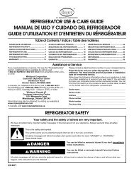
Quick Reference<br />
Table of Contents:<br />
Pages<br />
2 Before you start<br />
2 Product dimensions<br />
2 Cabinet dimensions/requirements<br />
3 Electrical requirements<br />
3 - 6 <strong>Installation</strong> steps<br />
Back cover If range does not operate<br />
Back cover If you need assistance/service<br />
Back cover Moving the range<br />
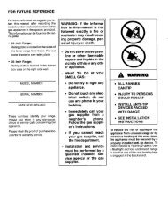
If you need assistance:<br />
Check your Use and Care Guide for a toll-free number to call or call the<br />
dealer from whom you purchased this appliance. The dealer is listed in<br />
the Yellow Pages of your phone directory under “Appliances —<br />
Household — Major — Service and Repair.”<br />
Call when you:<br />
Have questions about range installation or operation.<br />
Need to obtain the name and number of an authorized<br />
service company.<br />
When you call, you will need:<br />
The range model number.<br />
The range serial number.<br />
Both numbers are listed on the model/serial rating plate located on the<br />
oven frame behind the storage drawer panel.<br />
IMPORTANT:<br />
Read and save these instructions.<br />
IMPORTANT:<br />
Installer: Leave <strong>Installation</strong> <strong>Instructions</strong> with the homeowner.<br />
Homeowner: Keep <strong>Installation</strong> <strong>Instructions</strong> for future reference.<br />
Save <strong>Installation</strong> <strong>Instructions</strong> for local electrical inspector's use.<br />
Part No. 8522958
Page 2<br />
Before you start...<br />
Your safety and the safety of<br />
others are very important.<br />
We have provided many important safety<br />
messages in this manual and on your<br />
appliance. Always read and obey all safety<br />
messages.<br />
This is the safety alert symbol.<br />
This symbol alerts you to potential<br />
hazards that can kill or hurt you and others.<br />
All safety messages will be preceded by the<br />
safety alert symbol and the word “DANGER”<br />
or “WARNING”. These words mean:<br />
Important: Observe all governing codes and<br />
ordinances. Failure to meet codes and ordinances<br />
could lead to fire or electrical shock.<br />
Proper installation is your responsibility. A qualified<br />
technician must install this range. Make sure you<br />
have everything necessary for correct installation. It<br />
is the installer’s responsibility to comply with<br />
installation clearances specified on the model/serial<br />
rating plate. The model/serial rating plate is located<br />
on the oven frame behind the storage drawer panel.<br />
Check location where range will be installed. The<br />
range should be located for convenient use in<br />
kitchen.<br />
When installing a range under existing cabinets and<br />
the installation does not meet the minimum cabinet<br />
clearances, install a range hood above the cooktop<br />
to avoid burn hazards.<br />
ALL OPENINGS IN THE WALL OR FLOOR WHERE<br />
RANGE IS TO BE INSTALLED MUST BE SEALED.<br />
Cabinet opening dimensions that are shown must<br />
be used. Given dimensions are minimum<br />
clearances.<br />
Grounded electrical outlet is required. See<br />
“Electrical requirements,” Page 3.<br />
Mobile home installation<br />
The installation of this range must conform with the<br />
Manufactured Home Construction and Safety<br />
Standard, Title 24 CFR, Part 3280 [formerly the<br />
Federal Standard for Mobile Home Construction<br />
and Safety, Title 24, HUD (Part 280)] or, when such<br />
standard is not applicable, the Standard for<br />
Manufactured Home <strong>Installation</strong>s, ANSI/NCSBCS<br />
A225.1 and Manufactured Home <strong>Installation</strong>s, Sites<br />
and Communities ANSI/NFPA 501A*, or with local<br />
codes.<br />
When this range is installed in a mobile home, it<br />
must be secured to the floor during transit. Any<br />
method of securing the range is adequate as long<br />
as it conforms to the standards listed above.<br />
Four-wire power supply cord or cable must be used<br />
in a mobile home installation. The appliance wiring<br />
will need to be revised. See “Four-wire electrical<br />
connection,” Page 4.<br />
Copies of the standards listed may be obtained from:<br />
* National Fire Protection Association<br />
Batterymarch Park<br />
Quincy, Massachusetts 02269<br />
level<br />
flat-blade<br />
screwdriver<br />
measuring tape<br />
or ruler<br />
DANGER<br />
You can be killed or seriously injured if<br />
you don’t immediately follow<br />
instructions.<br />
WARNING<br />
You can be killed or seriously injured if<br />
you don’t follow instructions.<br />
All safety messages will tell you what the<br />
potential hazard is, tell you how to reduce<br />
the chance of injury, and tell you what can<br />
happen if the instructions are not followed.<br />
safety<br />
glasses<br />
hand or<br />
electric drill<br />
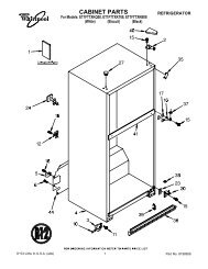
Product dimensions<br />
Cabinet dimensions/requirements<br />
18" min.<br />
clearance upper<br />
cabinet to<br />
countertop<br />
gloves<br />
27-1/8" depth<br />
with handle<br />
8 8 8<br />
13" max. upper<br />
cabinet depth<br />
The floor-mounted anti-tip<br />
bracket MUST be installed.<br />
To install the anti-tip<br />
bracket shipped with the<br />
range, see Page 3 and the<br />
anti-tip bracket template/<br />
instruction sheet.<br />
wood floors:<br />
1/8" drill bit<br />
concrete/ceramic floors:<br />
3/16" carbide-tipped masonry<br />
drill bit (Hammer may be<br />
needed for anchors.)<br />
channel lock<br />
pliers<br />
29-7/8" width<br />
5-1/2"<br />
max.<br />
Wall receptacle —<br />
8" to 22" from either<br />
cabinet, 5-1/2" max.<br />
from floor. Position<br />
receptacle as shown.<br />
For minimum<br />
clearance to the top<br />
of the cooktop, see<br />
Note.**<br />
**Note: 24" min. when bottom of wood or metal<br />
cabinet is protected by not less than 1/4" flame<br />
retardant millboard covered with not less than<br />
No. 28 MSG sheet steel, 0.015" stainless steel,<br />
0.024" aluminum or 0.020" copper.<br />
30" min. clearance between the top of the<br />
cooking platform and the bottom of an<br />
unprotected wood or metal cabinet.<br />
floor-mounted<br />
anti-tip bracket<br />
Do Not pinch the power<br />
supply cord between the<br />
range and the wall.<br />
Do Not seal the range to<br />
the side cabinets.<br />
Tools needed: Parts supplied:<br />
3/8" drive<br />
ratchet<br />
3/8" and 5/16"<br />
nut driver<br />
24-13/16"<br />
4" min.<br />
countertop<br />
space to side<br />
wall or other<br />
combustible<br />
material<br />
Anti-tip bracket<br />
30" min. cabinet<br />
opening width<br />
30-1/8" opening<br />
width<br />
36"<br />
cooktop<br />
height<br />
46-7/8"<br />
overall<br />
height<br />
2 screws (#10 x 1-1/2")<br />
2 plastic<br />
anchors<br />
Not shown:<br />
literature pack<br />
Brackets must be securely mounted to sub-floor. Thickness of<br />
flooring may require longer screws to anchor bracket to subfloor.<br />
Longer screws are available from your local hardware<br />
store.
Electrical requirements<br />
Electrical Shock Hazard<br />
Electrically ground range.<br />
Failure to follow this instruction could result in<br />
death, fire or electrical shock.<br />
If codes permit and a separate ground wire is used,<br />
it is recommended that a qualified electrician<br />
determine that the ground path and wire gauge are<br />
in accordance with local codes.<br />
Do Not ground to a gas pipe.<br />
Check with a qualified electrician if you are not<br />
sure range is properly grounded.<br />
Do Not have a fuse in the neutral or ground circuit.<br />
Recommended ground method<br />
It is the personal responsibility and obligation of the<br />
customer to contact a qualified electrician to assure<br />
that the electrical installation is adequate and is in<br />
conformance with the National Electrical Code,<br />
ANSI/NFPA 70 — latest edition* and all local codes<br />
and ordinances.<br />
Copies of the standards listed above may be<br />
obtained from:<br />
* National Fire Protection Association<br />
Batterymarch Park<br />
Quincy, Massachusetts 02269<br />
<strong>Installation</strong> steps<br />
A<br />
1. Put on safety glasses and gloves. Remove<br />
oven racks and parts package from inside oven.<br />
Remove shipping materials, tape and protective<br />
film from range.<br />
Page 3<br />
Preparation<br />
Excessive Weight Hazard<br />
Use two or more people to move and<br />
install range.<br />
Failure to do so can result in back or<br />
other injury.<br />
B<br />
WARNING<br />
WARNING<br />
Anti-tip bracket<br />
installation<br />
WARNING<br />
Tip Over Hazard<br />
A child or adult can tip the range and be<br />
killed.<br />
Connect anti-tip bracket to rear range foot.<br />
Reconnect the anti-tip bracket, if the range is<br />
moved.<br />
Failure to follow these instructions can result<br />
in death or serious burns to children and<br />
adults.<br />
Power supply cord is not supplied, but is available<br />
through your local electrical supply house.<br />
Range must be connected to the proper electrical<br />
voltage and frequency as specified on the<br />
model/serial rating plate. (The model/serial rating<br />
plate is located on the oven frame behind the<br />
storage drawer panel.)<br />
CONNECTION AT CONNECTION BLOCK MUST<br />
BE COPPER WIRE ONLY.<br />
If the house has aluminum wiring, follow the<br />
procedure below:<br />
a.) Connect a section of 8-gauge, solid copper<br />
wire to the connector block.<br />
b.) Connect the aluminum wiring to the added<br />
section of copper wire using special<br />
connectors designed and Underwriters<br />
Laboratories-listed for joining copper to<br />
aluminum. Follow the electrical connector<br />
manufacturer’s recommended procedure.<br />
c.) Aluminum/copper connection must conform<br />
with local codes and industry-accepted wiring<br />
practice.<br />
A three-wire or four-wire, single-phase, 120/240volt,<br />
60-Hz, AC-only, electrical supply (or three-wire<br />
or four-wire 120/208-volt if specified on the<br />
model/serial rating plate) is required on a separate,<br />
40-ampere circuit, fused on both sides of the line.<br />
A time-delay fuse or circuit breaker is<br />
recommended.<br />
Local codes may permit the use of a U.L.-listed,<br />
250-volt, 40-ampere range power supply cord<br />
(pigtail). This cord contains three, No.-10 copper<br />
wires and matches a three-wire receptacle of NEMA<br />
Type 10-50R, shown in Figure 1. Connectors on the<br />
appliance end must be provided at the point the<br />
power supply cord enters the appliance.<br />
The range can be connected directly to the<br />
fused disconnect (or circuit breaker box) through<br />
flexible, armored or non-metallic sheathed, copper<br />
cable (with grounding wire). Allow two to three feet<br />
of slack in the line so that it can be moved if<br />
servicing is ever necessary.<br />
cardboard<br />
shipping base<br />
2.Do Not remove the cardboard shipping<br />
base at this time.<br />
Contact a qualified floor covering installer for the<br />
best procedure for drilling mounting holes through<br />
your type floor covering.<br />
4.Use the anti-tip bracket template/ instruction<br />
sheet to install the anti-tip bracket.<br />
A U.L.-listed conduit connector must be provided at<br />
each end of the power supply cable (at the range<br />
and at the junction box).<br />
Wire sizes (COPPER WIRE ONLY) and connections<br />
must conform with the rating of the range<br />
(40-amperes).<br />
The wiring diagram is located on the back of<br />
the range or on the inside of the storage drawer in a<br />
clear plastic bag.<br />
If connecting to a four-wire system:<br />
This range is manufactured with the ground<br />
connected to the cabinet. The ground must be<br />
revised so the green grounding wire of the fourwire<br />
power supply cord is connected to the cabinet.<br />
See “Four-wire electrical connection,” section,<br />
Page 4.<br />
When a four-wire receptacle of NEMA Type 14-50R<br />
is used (see Figure 2), a matching U.L.-listed, fourwire,<br />
250-volt, 40-ampere, range power supply cord<br />
(pigtail) must be used. This cord contains four<br />
copper conductors with ring terminals at the<br />
appliance end, terminating in a NEMA Type 14-50P<br />
plug on the supply end. The fourth (grounding)<br />
conductor must be identified by a green or<br />
green/yellow cover and the neutral conductor by a<br />
white cover. Cord should be Type SRD or SRDT<br />
with a U.L.-listed strain relief and be at least four<br />
feet long.<br />
The MINIMUM conductor sizes for the copper<br />
four-wire power cord are:<br />
40-ampere circuit<br />
2, No.-8 conductors<br />
1, No.-10 white neutral<br />
1, No.-8 green grounding<br />
3-wire wall<br />
receptacle (10-50R)<br />
4-wire wall<br />
receptacle (14-50R)<br />
Figure 1 Figure 2<br />
rear leveling leg<br />
front leveling leg<br />
3.Remove storage drawer. Use a 3/8" drive<br />
ratchet to lower rear leveling legs one-half<br />
turn. Use channel lock pliers to lower front<br />
leveling legs one-half turn.<br />
Anti-tip bracket must be anchored securely to the<br />
sub-floor.<br />
Depending on the thickness of your flooring,<br />
longer screws may be necessary to anchor the<br />
bracket to the sub-floor. Longer screws are<br />
available from your local hardware store.<br />
Check that range is on cardboard shipping base<br />
to protect floor covering.
C<br />
Electrical connection<br />
GROUNDING INSTRUCTIONS: This range must<br />
be grounded. In the event of malfunction or<br />
breakdown, grounding will reduce the risk of<br />
electric shock by providing a path of least<br />
resistance for electric current.<br />
If using a power supply cord, the plug must be<br />
plugged into an appropriate outlet that is<br />
properly installed and grounded in accordance<br />
with all local codes and ordinances.<br />
If using a direct wire connection, this range must<br />
be connected to a grounded metal, permanent<br />
wiring system; or an equipment-ground<br />
conductor must be run with the circuit<br />
conductors and connected to the equipmentground<br />
terminal or lead on the range.<br />
Power supply cord method:<br />
Electrical Shock Hazard<br />
Turn power supply off before connecting cord.<br />
Use a new 40-ampere power supply cord.<br />
Plug into a grounded outlet.<br />
Failure to follow these instructions can result<br />
in death, fire, or electrical shock.<br />
This range is manufactured with the neutral<br />
terminal connected to the cabinet. Use a three-wire,<br />
U.L.-listed, 40-ampere power supply cord (pigtail);<br />
or if local codes Do Not permit ground through the<br />
neutral, use a four-wire power supply cord rated at<br />
250 volts, 40-amperes and investigated for use with<br />
ranges. (See “Four-wire electrical connection.”)<br />
remove knockout<br />
for 40-ampere<br />
power cord and<br />
U.L. listed strain<br />
relief<br />
opening for<br />
conduit<br />
connector<br />
1. Disconnect the power supply.<br />
2. Remove the knockout for the 40-ampere power<br />
supply cord.<br />
3. Assemble a U.L.-listed strain relief in the opening.<br />
4. Insert the power supply cord through the strain<br />
relief, allowing enough slack to easily attach the<br />
wiring to the terminal block.<br />
5. Use only ring-type terminals to connect the<br />
power supply. To secure the power supply cord,<br />
use the 3/8" brass terminal nuts attached to the<br />
inside of the terminal block cover. Be sure nuts<br />
are installed tight.<br />
6. Complete electrical connection according to your<br />
type electrical supply (“Three-wire electrical<br />
connection” or “Four-wire electrical connection.”)<br />
Page 4<br />
WARNING<br />
WARNING - Improper connection of the equipmentgrounding<br />
conductor can result in a risk of electric<br />
shock. Check with a qualified electrician or<br />
serviceman if you are in doubt as to whether the<br />
appliance is properly grounded. Do not modify the<br />
power supply cord plug. If it will not fit the outlet,<br />
have a proper outlet installed by a qualified<br />
electrician.<br />
Pull cover down and<br />
towards you to<br />
remove.<br />
2 mounting<br />
tabs, each side<br />
hex-head<br />
screws<br />
7. Depending on your electrical supply, make<br />
the three-wire or four-wire connection following<br />
the “Power supply cord method” or “Direct wire<br />
method” instructions.<br />
Four-wire electrical connection:<br />
ground<br />
link<br />
neutral wire<br />
(center wire)<br />
line 1<br />
Figure 4<br />
Figure 5<br />
terminal<br />
block cover<br />
3/8"<br />
brass nuts<br />
located inside<br />
cover<br />
6.Remove the terminal block cover screws<br />
located on the back of range. Pull cover down and<br />
towards you to remove cover from range.<br />
ground<br />
link<br />
ground-link<br />
screw<br />
ground-link<br />
screw<br />
silver-colored<br />
terminal<br />
block screw<br />
green<br />
ground wire<br />
line 2<br />
U.L. listed strain<br />
relief and 40-ampere<br />
range power supply<br />
cord<br />
Use this method for mobile homes and whenever<br />
four-wire installation is required.<br />
7. Remove the ground-link screw from the<br />
range frame. Save the ground-link screw.<br />
Bend up the ground link so that it does not<br />
contact the range. See Figure 4.<br />
8. Connect the green ground wire from power<br />
supply cord to the range using the groundlink<br />
screw. The ground wire must be<br />
attached first and must not contact any other<br />
terminal. See Figure 5.<br />
9. Connect the neutral wire (center wire) to the<br />
center, silver-colored terminal screw on the<br />
terminal block using the brass terminal nuts<br />
that are attached to the inside of the terminal<br />
block cover. See Figure 5.<br />
10. Connect the other two wires to the outer<br />
terminals on the terminal block. See Figure 5.<br />
11. Do Not loosen the factory-installed nuts<br />
already on the terminal. Tighten nuts with 3/8"<br />
nut driver for proper electrical connection.<br />
12. Tighten the strain relief screws.<br />
13. Replace the terminal block cover.<br />
14. Plug power supply cord into grounded<br />
electrical outlet.<br />
Three-wire electrical connection:<br />
silver-colored<br />
terminal<br />
block screw<br />
line 1<br />
Figure 3<br />
ground link<br />
line 2<br />
neutral<br />
(center wire)<br />
U.L.-listed strain relief<br />
and 40-ampere range<br />
power supply cord<br />
Use this method ONLY if local codes PERMIT<br />
connecting cabinet-ground conductor to neutral<br />
wire of power supply cord.<br />
7. Use the brass terminal nuts attached to the<br />
inside of the terminal block cover to connect<br />
the neutral wire (center wire) to the silvercolored<br />
terminal screw on the terminal block.<br />
See Figure 3.<br />
8. Connect the other two wires to outer<br />
terminal screws on the terminal block. See<br />
Figure 3.<br />
9. Do Not loosen factory-installed nuts already<br />
on the terminal. Tighten nuts with 3/8" nut<br />
driver for proper electrical connection.<br />
10. Tighten the strain relief screws.<br />
11. Replace the terminal block cover.<br />
12. Plug power supply cord into grounded<br />
electrical outlet.
Direct wire method:<br />
This range may be connected directly to the fuse<br />
disconnect or circuit breaker box; or with a U.L.listed,<br />
40-ampere range power supply cable.<br />
Depending on your electrical supply, make the<br />
required three-wire or four-wire connection.<br />
U.L.-listed conduit<br />
connector.<br />
1. Disconnect the power supply.<br />
2. Remove the knockout for the power supply<br />
cable.<br />
3. Assemble a U.L.-listed conduit connector in<br />
the power supply cable opening.<br />
4. Strip outer covering back 3 inches from end,<br />
exposing wires. Strip the insulation back<br />
1 inch from the end of each wire.<br />
D<br />
Operating position<br />
Before moving range across floor, check that<br />
range is still on cardboard shipping base to<br />
protect floor covering.<br />
9.If installing the range in a mobile home,<br />
you MUST secure the range to the floor. Any<br />
method of securing the range is adequate as<br />
long as it conforms to the standards in the<br />
“Mobile home installation” instructions, Page 2.<br />
10.Place rack in oven. Place<br />
level on rack, first side to side; then front to back.<br />
If range is not level, pull range forward until rear<br />
leveling leg is removed from the anti-tip bracket.<br />
Use 3/8" drive ratchet and channel lock pliers to<br />
adjust leveling legs up or down until range is<br />
level. Push range back into position. Check that<br />
rear leveling leg is engaged in anti-tip bracket.<br />
Note: Oven must be level for satisfactory baking<br />
conditions.<br />
11. Replace the storage drawer or lower<br />
panel.<br />
Page 5<br />
WARNING<br />
Electrical Shock Hazard<br />
Turn power supply off before connecting<br />
wires.<br />
Use 8-gauge solid copper wire.<br />
Electrically ground range.<br />
Failure to follow these instructions can result<br />
in death, fire, or electrical shock.<br />
anti-tip<br />
bracket<br />
1”<br />
range foot<br />
8.Making sure the anti-tip bracket is<br />
installed:<br />
3”<br />
• Look for the anti-tip bracket securely attached<br />
to floor.<br />
• Slide range back so rear range foot is under<br />
anti-tip bracket.<br />
5. Form the bare wire into a<br />
“U”-shaped hook.<br />
6. Insert the power supply cable<br />
through the conduit connector,<br />
allowing enough slack to easily<br />
attach the<br />
wiring terminal block.<br />
7. Complete electrical connection according to<br />
your type electrical supply (“Three-wire<br />
electrical connection” or “Four-wire<br />
electrical connection.”)<br />
Four-wire electrical connection:<br />
ground<br />
link<br />
bare wire<br />
from power<br />
supply cable<br />
line 1<br />
Figure 7<br />
Figure 8<br />
ground-link<br />
screw<br />
silver-colored<br />
terminal block<br />
screw<br />
neutral wire<br />
(white wire)<br />
line 2<br />
U.L. listed<br />
conduit<br />
connector and<br />
power supply<br />
cable<br />
Use this method for mobile homes and<br />
whenever four-wire installation is required.<br />
8. Remove the ground-link screw from the<br />
range frame. Save the ground-link<br />
screw. Bend up the ground link so that it<br />
does not contact the range. See Figure 7.<br />
9. Connect the bare ground wire from<br />
power supply cable to the range using the<br />
ground-link screw. The ground wire<br />
must be attached first and must not<br />
contact any other terminal. See Figure 8.<br />
E<br />
Check operation<br />
FRONT<br />
2<br />
LO HI<br />
3<br />
OFF<br />
4 6<br />
5<br />
12.Check the operation of the cooktop<br />
elements: Push in and turn each surface unit<br />
control knob to “HI” position. Check the operation<br />
of the cooktop elements and indicator lights.<br />
13.Check the operation of the oven and<br />
broil elements: Follow the instructions for your<br />
type oven controls.<br />
If your range has oven temperature<br />
control knob:<br />
OVEN ON<br />
(TURN OFF OVEN WHEN FLASHING)<br />
OVEN HEATING<br />
DOOR LOCKED/CLEANING<br />
(CLOSE DOOR WHEN FLASHING)<br />
CLEAN<br />
PUSH TO<br />
TURN<br />
BROIL<br />
7<br />
450<br />
8<br />
OFF<br />
400<br />
PUSH TO<br />
TURN<br />
WARM<br />
1. Set the oven temperature control to 350°F.<br />
• The bottom element should glow red and the<br />
“OVEN ON” and “OVEN HEATING” indicator<br />
lights should be on.<br />
• The upper element should become hot but<br />
not glow red. The “OVEN HEATING” indicator<br />
light goes off when the oven is preheated.<br />
2. Set the oven temperature control to “BROIL.”<br />
• The upper element should glow red and the<br />
“OVEN ON” and “OVEN HEATING”indicator<br />
lights should be on.<br />
3. Turn the control knob to the “OFF” position.<br />
500<br />
350<br />
200<br />
250<br />
300<br />
10. Connect the neutral wire (white wire) to the<br />
center, silver-colored terminal screw on the<br />
terminal block using the brass terminal<br />
nuts that are attached to the inside of the<br />
terminal block cover. See Figure 8.<br />
11. Connect the other two wires to the outer<br />
terminals on the terminal block.<br />
See Figure 8.<br />
12. Do NOT loosen the factory-installed nuts<br />
already on the terminal. Tighten nuts with<br />
3/8" nut driver for proper electrical<br />
connection.<br />
13. Tighten the locking ring and clamping<br />
screws of the conduit connector.<br />
14. Replace the terminal block cover.<br />
Three-wire electrical connection:<br />
ground<br />
link<br />
line 1<br />
Figure 6<br />
silver-colored<br />
terminal block<br />
screw<br />
line 2<br />
neutral<br />
(white wire)<br />
U.L.-listed conduit<br />
connector and power<br />
supply cable.<br />
Use this method ONLY if local codes PERMIT<br />
connecting cabinet-ground conductor to<br />
neutral wire of power supply cable.<br />
8. Use the brass terminal nuts attached to the<br />
inside of the terminal block cover to<br />
connect the neutral wire (white wire) to the<br />
silver-colored terminal screw on the<br />
terminal block. See Figure 6.<br />
9. Connect the other two wires to outer<br />
terminal screws on the terminal block.<br />
See Figure 6.<br />
10. Do Not loosen factory-installed nuts<br />
already on the terminal. Tighten nuts<br />
with 3/8" nut driver for proper electrical<br />
connection.<br />
11. Tighten the locking ring and clamping<br />
screws of the conduit connector.<br />
12. Replace the terminal block cover.<br />
If your range has oven selector and<br />
temperature control knobs:<br />
OFF<br />
BROIL BAKE<br />
500<br />
BROIL<br />
450<br />
400<br />
350<br />
OFF<br />
300<br />
250<br />
150<br />
200<br />
1. Set the oven selector control to “BAKE” and<br />
the oven temperature control to 350°.<br />
• The bottom element should glow red and the<br />
indicator light should be on.<br />
• The upper element should become hot but<br />
not glow red. The oven indicator light goes<br />
off when the oven is preheated.<br />
2. Set the oven selector to “BROIL” and the oven<br />
temperature control to “BROIL”.<br />
• The upper element should glow red and the<br />
indicator light should be on.<br />
3. Turn the control knob to the “OFF” position.
1. Press the “BAKE” pad.<br />
• The “BAKE” indicator will light.<br />
• “350°F” will appear in the display.<br />
2. Press the START/ENTER pad.<br />
• “PrE” and “4:15” will appear in the display.<br />
• “HEAT” and “ON” and indicators will light.<br />
• The bottom element should glow red.<br />
• The upper element should become hot but not<br />
glow red.<br />
The oven is preheated when the time in the display<br />
counts down to “0:00,” you hear a 1-second tone,<br />
and “PrE” changes to “350°F.”<br />
3. Press the “OFF/CANCEL” pad.<br />
4. Press the “CUSTOM BROIL” pad.<br />
• “500°F” will appear in the display.<br />
• “BROIL” indicator will light.<br />
1. Press the “BAKE” pad.<br />
• The “BAKE” indicator will light.<br />
• “350°F” will appear in the display.<br />
• The “START ?” indicator will light after 5<br />
seconds.<br />
2. Press the START/ENTER pad.<br />
• “PrE” and the preheat countdown time will<br />
appear in the display.<br />
• “HEAT” and “ON” and indicators will light.<br />
• The bottom element should glow red.<br />
• The upper element should become hot but not<br />
glow red.<br />
The oven is preheated when the time in the display<br />
counts down to “0:00,” you hear a 1-second tone,<br />
and “PrE” changes to “350°F.”<br />
3. Press the “OFF/CANCEL” pad.<br />
4. Press the “CUSTOM BROIL” pad.<br />
• “500°F” will appear in the display.<br />
• “BROIL” indicator will light.<br />
• The “START ?” indicator will light after 5<br />
seconds.<br />
5. Press the “START/ENTER” pad.<br />
• “HEAT” and “ON” indicators will light.<br />
• The upper element should glow red.<br />
6. Press the “OFF/CANCEL” pad.<br />
Page 6<br />
If your oven has one of these three electronic control consoles:<br />
1. Press the “BAKE” pad.<br />
• The “BAKE” indicator will light.<br />
• “350” will appear in the display.<br />
• The “START ?” indicator will begin<br />
to flash after 5 seconds.<br />
2. Press the START/ENTER pad.<br />
• The “HEAT” and “ON” indicators will light.<br />
• The display will show the automatic countdown<br />
time (6 minutes) needed to preheat the oven for<br />
selected temperature.<br />
• The bottom element should glow red.<br />
• The upper element should become hot, but not<br />
glow red.<br />
The oven is preheated when the “HEAT” indicator<br />
light goes off, you hear a 1-second tone and the<br />
countdown changes to “350”.<br />
* Note: BAKE PREHEAT mode will not become<br />
active if oven temperature is over 170°F; instead,<br />
the BAKE mode immediately becomes active.<br />
3. Press the “OFF/CANCEL” pad.<br />
4. Press the “CUSTOM BROIL” pad.<br />
• “500” will appear in the display.<br />
• The “BROIL” indicator will light.<br />
• The “START ?” indicator will begin to flash after<br />
5 seconds.<br />
5. Press the “START/ENTER” pad.<br />
• The “ON” and “HEAT”indicators will light.<br />
• The upper element should glow red.<br />
6. Press the “OFF/CANCEL” pad.<br />
If your oven has this electronic control console and a timer:<br />
BAKE<br />
BROIL<br />
START ?<br />
HEAT<br />
CLEAN<br />
DOOR LOCKED<br />
888° F 88:88<br />
ON<br />
HEAT BAKE BROIL LOCKED CLEAN TIMER<br />
TIMER<br />
BAKE CUSTOM AUTO TEMP CLOCK<br />
SET<br />
LIGHT HR MIN<br />
TIMER<br />
OFF<br />
5. Press the “START/ENTER” pad.<br />
• “HEAT” and “ON” indicators will light.<br />
• The upper element should glow red.<br />
6. Press the “OFF/CANCEL” pad.<br />
If your oven has one of these three electronic control consoles and a timer:<br />
SELF-CLEANING OVEN<br />
FIRST/<br />
NEXT<br />
STEP<br />
REVIEW<br />
STEPS<br />
UNDO<br />
BAKE<br />
SELF-CLEANING OVEN<br />
BAKE<br />
SELF-CLEANING OVEN<br />
FIRST/<br />
NEXT<br />
STEP<br />
REVIEW<br />
STEPS<br />
UNDO<br />
BAKE<br />
AUTO<br />
CLEAN<br />
To get the most efficient use from your new electric range, read<br />
your Use and Care Guide. Keep <strong>Installation</strong> <strong>Instructions</strong> and Guide<br />
close to the electric range for easy reference.<br />
BAKE<br />
BAKE<br />
BROIL<br />
START ?<br />
HEAT<br />
CLEAN<br />
BAKE<br />
BAKE<br />
BROIL<br />
HEAT<br />
CLEAN<br />
DOOR<br />
LOCKED<br />
BAKE<br />
CUSTOM<br />
BROIL<br />
CUSTOM<br />
BROIL<br />
CUSTOM<br />
BROIL<br />
CUSTOM<br />
BROIL<br />
TIMER<br />
DOOR LOCKED<br />
CUSTOM<br />
BROIL<br />
START TIME/<br />
DELAY<br />
TEMP/ TEMP<br />
TIME<br />
ON<br />
88 88<br />
AUTO<br />
CLEAN<br />
TEMP/ TEMP<br />
TIME<br />
ON<br />
88 88<br />
COOK TIME/<br />
TIMED<br />
CUSTOM<br />
BROIL<br />
WARM CHOICE<br />
BAKE<br />
WARM CHOICE<br />
BAKE<br />
WARM CHOICE<br />
BAKE<br />
TIMER<br />
AUTO<br />
CLEAN<br />
TEMP/ TEMP<br />
TIME<br />
ON<br />
88 88<br />
WARMING<br />
DRAWER<br />
DRAWER<br />
OFF<br />
START ?<br />
TEMP<br />
TEMP<br />
TEMP<br />
START<br />
TIME<br />
TEMP<br />
COOK<br />
TIME<br />
START<br />
TIME<br />
START<br />
TIME<br />
START<br />
TIME<br />
STOP<br />
TIME<br />
STOP<br />
TIME<br />
STOP<br />
TIME<br />
SELF CLEANING OVEN<br />
CLOCK<br />
TIMER TEMP<br />
**CANCEL<br />
START<br />
ENTER<br />
5 SEC<br />
START<br />
ENTER<br />
5 SEC<br />
OFF<br />
CANCEL<br />
SELF CLEANING OVEN<br />
SELF CLEANING OVEN<br />
CLOCK<br />
TIMER TEMP<br />
**CANCEL<br />
TIMER<br />
SET<br />
TIMER<br />
OFF<br />
START<br />
ENTER<br />
5 SEC<br />
CLOCK<br />
AUTO<br />
CLEAN<br />
HR MIN<br />
TIMER<br />
SET<br />
TIMER<br />
OFF<br />
CLOCK<br />
AUTO<br />
CLEAN<br />
HR MIN<br />
TIMER<br />
SET<br />
TIMER<br />
OFF<br />
CLOCK<br />
AUTO<br />
CLEAN<br />
HR MIN<br />
OFF<br />
CANCEL<br />
OFF<br />
CANCEL<br />
START<br />
5 SEC<br />
START OFF<br />
5 SEC<br />
OVEN<br />
LIGHT<br />
CANCEL<br />
START OFF<br />
5 SEC<br />
OVEN<br />
LIGHT<br />
CANCEL<br />
START OFF<br />
5 SEC<br />
OVEN<br />
LIGHT<br />
CANCEL<br />
OFF
If range does not operate:<br />
Check that the circuit breaker is not tripped or<br />
the house fuse blown.<br />
Check that the power supply cord is plugged<br />
into the wall receptacle.<br />
See Use and Care Guide for troubleshooting<br />
list.<br />
If you need assistance:<br />
If you have questions about operating, cleaning or<br />
maintaining your range:<br />
Refer to Use and Care Guide.<br />
Call the Consumer Assistance Center. Check<br />
your Use and Care Guide for a toll-free number<br />
to call or call the dealer from whom you<br />
purchased this appliance. The dealer is listed in<br />
the Yellow Pages of your phone directory under<br />
“Appliances — Household —Major — Service<br />
and Repair.”<br />
If you need service:<br />
Maintain the quality built into your range by calling an<br />
authorized service company.<br />
To obtain the name and number of the authorized<br />
service company:<br />
Contact the dealer from whom you purchased<br />
your range; or<br />
Look in the Yellow Pages of your telephone<br />
directory under “Appliances — Household —<br />
Major — Service and Repair;” or<br />
Call the Consumer Assistance Center.<br />
The toll-free number is listed in your Use and<br />
Care Guide.<br />
When you call, you will need:<br />
The range model number.<br />
The range serial number.<br />
Both numbers are listed on the model/serial rating<br />
plate located on the oven frame behind the storage<br />
drawer panel.<br />
Part No. 8522958<br />
Moving the range:<br />
WARNING<br />
Tip Over Hazard<br />
A child or adult can tip the range and be killed.<br />
Connect anti-tip bracket to rear range foot.<br />
Reconnect the anti-tip bracket, if the range is<br />
moved.<br />
Failure to follow these instructions can result in<br />
death or serious burns to children and adults.<br />
When moving range, slide range onto cardboard or<br />
hardboard to prevent damaging the floor covering.<br />
If removing the range is necessary for cleaning or<br />
maintenance:<br />
1. Disconnect the electrical supply. If necessary,<br />
pull the range out, away from the wall, just far<br />
enough to disconnect the power supply cord.<br />
2. Slide range forward to complete cleaning or<br />
maintenance.<br />
3. Making sure the anti-tip bracket is installed:<br />
• Look for the anti-tip bracket securely attached<br />
to floor.<br />
• Slide range back so rear range foot is under<br />
anti-tip bracket.<br />
4. Check that range is level.<br />
5. Reconnect the electrical supply. Reinstall storage<br />
drawer.<br />
© 2001 <strong>Whirlpool</strong> <strong>Corporation</strong> Benton Harbor, Michigan 49022<br />
Printed in U.S.A.<br />
anti-tip<br />
bracket<br />
range foot