- Page 2 and 3:
T-FLEX Parametric CAD FUNDAMENTALS.
- Page 4 and 5:
TABLE OF CONTENTS Table of Contents
- Page 6 and 7:
Table of Contents “Commands” Ta
- Page 8 and 9:
Table of Contents Basic Rules of Gr
- Page 10 and 11:
Table of Contents Leader Note Examp
- Page 12 and 13:
Table of Contents Creating List of
- Page 14 and 15:
Table of Contents Defining Fragment
- Page 16 and 17:
Table of Contents Creating a Databa
- Page 18 and 19:
Introduction T-FLEX CAD: Features a
- Page 20 and 21:
Features and Area of Application lo
- Page 22 and 23:
Conventions Adopted in the T-FLEX C
- Page 24 and 25:
System Fundamentals. Customization
- Page 26 and 27:
T-FLEX CAD System Setup Running Ins
- Page 28 and 29:
Service Windows and Elements of Con
- Page 30 and 31:
Macros Window Studies Window (only
- Page 32 and 33:
To add a tool window to an already
- Page 34 and 35:
Getting Started Typically, nodes ar
- Page 36 and 37:
Leader Note is a standard element o
- Page 38 and 39:
Non-parametric Drawing (Sketch). Th
- Page 40 and 41:
Using Left Mouse Button • Pointin
- Page 42 and 43:
Getting Started In this volume, any
- Page 44 and 45:
Canceling a Command Getting Started
- Page 46 and 47:
Getting Started “PS: Show Model P
- Page 48 and 49:
BRIEF INTRODUCTORY COURSE Brief Int
- Page 50 and 51:
Brief Introductory Course To draw t
- Page 52 and 53:
Brief Introductory Course Move the
- Page 54 and 55:
Brief Introductory Course Note that
- Page 56 and 57:
Another way of creating nodes is us
- Page 58 and 59:
Brief Introductory Course dimension
- Page 60 and 61:
To explicitly call the text editing
- Page 62 and 63:
Brief Introductory Course This comm
- Page 64 and 65:
You are still within the segment cr
- Page 66 and 67:
Now, let’s construct the left sid
- Page 68 and 69:
Brief Introductory Course Click , f
- Page 70 and 71:
Line Midpoint Horizontal/Vertical O
- Page 72 and 73:
Brief Introductory Course We will s
- Page 74 and 75:
Click and move the cursor leftwards
- Page 76 and 77:
Brief Introductory Course Next, mov
- Page 78 and 79:
Brief Introductory Course Next we n
- Page 80 and 81:
MAIN CONCEPTS OF SYSTEM OPERATION D
- Page 82 and 83:
Main Concepts of System Operation m
- Page 84 and 85:
Main Concepts of System Operation w
- Page 86 and 87:
Main Concepts of System Operation L
- Page 88 and 89:
Main Concepts of System Operation T
- Page 90 and 91:
This window can be floating or dock
- Page 92 and 93:
Active Drawing Window The T-FLEX CA
- Page 94 and 95:
An alternative way of maximizing a
- Page 96 and 97:
Main Concepts of System Operation T
- Page 98 and 99:
2. Tile Vertically. Do this by the
- Page 100 and 101:
Additional window of document Main
- Page 102 and 103:
Main Concepts of System Operation i
- Page 104 and 105:
Main Concepts of System Operation T
- Page 106 and 107:
Main Concepts of System Operation w
- Page 108 and 109:
A system-offered object snap can be
- Page 110 and 111:
Main Concepts of System Operation T
- Page 112 and 113:
General Concepts of Editing Element
- Page 114 and 115:
The context menu of an element can
- Page 116 and 117:
Main Concepts of System Operation w
- Page 118 and 119:
Filter There are several additional
- Page 120 and 121:
Main Concepts of System Operation A
- Page 122 and 123:
Main Concepts of System Operation T
- Page 124 and 125:
Main Concepts of System Operation C
- Page 126 and 127:
Layer Main Concepts of System Opera
- Page 128 and 129:
When using a variable for defining
- Page 130 and 131:
Main Concepts of System Operation T
- Page 132 and 133:
CUSTOMIZING SYSTEM Customizing Syst
- Page 134 and 135:
Load Previous Session Document on S
- Page 136 and 137:
Customizing System “Save” Tab A
- Page 138 and 139:
“Snap” Tab Customizing System T
- Page 140 and 141:
“Folders” Tab This tab is used
- Page 142 and 143:
Customizing System The “Scene rot
- Page 144 and 145:
Customizing System Additional flag
- Page 146 and 147:
Controlling Toolbar Visibility To s
- Page 148 and 149:
“Keyboard” Tab This tab defines
- Page 150 and 151:
Customizing System To modify alread
- Page 152 and 153:
Customizing System The buttons [App
- Page 154 and 155:
Customizing System - Mapping of the
- Page 156 and 157:
Customizing System Upon pressing th
- Page 158 and 159:
CUSTOMIZING DRAWING Customizing Dra
- Page 160 and 161:
Customizing Drawing Direction. Defi
- Page 162 and 163:
Customizing Drawing “Dimensions
- Page 164 and 165:
Customizing Drawing “Alternative
- Page 166 and 167:
Customizing Drawing “Preferences
- Page 168 and 169:
Customizing Drawing “Colors” Ta
- Page 170 and 171:
Customizing Drawing Default truncat
- Page 172 and 173:
Customizing Drawing “3D” Tab Th
- Page 174 and 175:
Customizing Drawing The command bri
- Page 176 and 177:
Libraries Active Configuration. Thi
- Page 178 and 179:
Libraries Cut, copy, paste. These c
- Page 180 and 181:
Libraries the model menu window is
- Page 182 and 183:
Pages Switching pages is done witho
- Page 184 and 185:
Pages The quickest way of creating
- Page 186:
Special Handling of Multi-Page Docu
- Page 189 and 190:
Fundamentals. Two-Dimensional Desig
- Page 191 and 192:
Fundamentals. Two-Dimensional Desig
- Page 193 and 194:
Fundamentals. Two-Dimensional Desig
- Page 195 and 196:
Fundamentals. Two-Dimensional Desig
- Page 197 and 198:
Fundamentals. Two-Dimensional Desig
- Page 199 and 200:
Fundamentals. Two-Dimensional Desig
- Page 201 and 202:
Fundamentals. Two-Dimensional Desig
- Page 203 and 204:
Fundamentals. Two-Dimensional Desig
- Page 205 and 206:
Fundamentals. Two-Dimensional Desig
- Page 207 and 208:
Fundamentals. Two-Dimensional Desig
- Page 209 and 210:
Fundamentals. Two-Dimensional Desig
- Page 211 and 212:
Fundamentals. Two-Dimensional Desig
- Page 213 and 214:
Fundamentals. Two-Dimensional Desig
- Page 215 and 216:
Fundamentals. Two-Dimensional Desig
- Page 217 and 218:
Fundamentals. Two-Dimensional Desig
- Page 219 and 220:
Fundamentals. Two-Dimensional Desig
- Page 221 and 222:
Fundamentals. Two-Dimensional Desig
- Page 223 and 224:
Fundamentals. Two-Dimensional Desig
- Page 225 and 226:
Fundamentals. Two-Dimensional Desig
- Page 227 and 228:
Fundamentals. Two-Dimensional Desig
- Page 229 and 230:
Fundamentals. Two-Dimensional Desig
- Page 231 and 232:
Fundamentals. Two-Dimensional Desig
- Page 233 and 234:
Fundamentals. Two-Dimensional Desig
- Page 235 and 236:
Fundamentals. Two-Dimensional Desig
- Page 237 and 238:
Fundamentals. Two-Dimensional Desig
- Page 239 and 240:
Fundamentals. Two-Dimensional Desig
- Page 241 and 242:
Fundamentals. Two-Dimensional Desig
- Page 243 and 244:
Fundamentals. Two-Dimensional Desig
- Page 245 and 246:
Fundamentals. Two-Dimensional Desig
- Page 247 and 248:
Fundamentals. Two-Dimensional Desig
- Page 249 and 250:
Fundamentals. Two-Dimensional Desig
- Page 251 and 252:
Fundamentals. Two-Dimensional Desig
- Page 253 and 254:
Fundamentals. Two-Dimensional Desig
- Page 255 and 256:
Fundamentals. Two-Dimensional Desig
- Page 257 and 258:
Fundamentals. Two-Dimensional Desig
- Page 259 and 260:
Fundamentals. Two-Dimensional Desig
- Page 261 and 262:
Fundamentals. Two-Dimensional Desig
- Page 263 and 264:
Fundamentals. Two-Dimensional Desig
- Page 265 and 266:
Fundamentals. Two-Dimensional Desig
- Page 267 and 268:
Fundamentals. Two-Dimensional Desig
- Page 269 and 270:
Fundamentals. Two-Dimensional Desig
- Page 271 and 272:
Fundamentals. Two-Dimensional Desig
- Page 273 and 274:
Fundamentals. Two-Dimensional Desig
- Page 275 and 276:
Fundamentals. Two-Dimensional Desig
- Page 277 and 278:
Fundamentals. Two-Dimensional Desig
- Page 279 and 280:
Fundamentals. Two-Dimensional Desig
- Page 281 and 282:
Fundamentals. Two-Dimensional Desig
- Page 283 and 284:
Fundamentals. Two-Dimensional Desig
- Page 285 and 286:
Fundamentals. Two-Dimensional Desig
- Page 287 and 288:
Fundamentals. Two-Dimensional Desig
- Page 289 and 290:
Fundamentals. Two-Dimensional Desig
- Page 291 and 292:
Fundamentals. Two-Dimensional Desig
- Page 293 and 294:
Fundamentals. Two-Dimensional Desig
- Page 295 and 296:
Fundamentals. Two-Dimensional Desig
- Page 297 and 298:
Fundamentals. Two-Dimensional Desig
- Page 299 and 300:
Fundamentals. Two-Dimensional Desig
- Page 301 and 302:
Fundamentals. Two-Dimensional Desig
- Page 303 and 304:
Fundamentals. Two-Dimensional Desig
- Page 305 and 306:
Fundamentals. Two-Dimensional Desig
- Page 307 and 308:
Fundamentals. Two-Dimensional Desig
- Page 309 and 310:
Fundamentals. Two-Dimensional Desig
- Page 311 and 312:
Fundamentals. Two-Dimensional Desig
- Page 313 and 314:
Fundamentals. Two-Dimensional Desig
- Page 315 and 316:
Fundamentals. Two-Dimensional Desig
- Page 317 and 318:
Fundamentals. Two-Dimensional Desig
- Page 319 and 320:
Fundamentals. Two-Dimensional Desig
- Page 321 and 322:
Fundamentals. Two-Dimensional Desig
- Page 323 and 324:
Fundamentals. Two-Dimensional Desig
- Page 325 and 326:
Fundamentals. Two-Dimensional Desig
- Page 327 and 328:
Fundamentals. Two-Dimensional Desig
- Page 329 and 330:
Fundamentals. Two-Dimensional Desig
- Page 331 and 332:
Fundamentals. Two-Dimensional Desig
- Page 333 and 334:
Fundamentals. Two-Dimensional Desig
- Page 335 and 336:
Fundamentals. Two-Dimensional Desig
- Page 337 and 338:
Fundamentals. Two-Dimensional Desig
- Page 339 and 340:
Fundamentals. Two-Dimensional Desig
- Page 341 and 342:
Fundamentals. Two-Dimensional Desig
- Page 343 and 344:
Fundamentals. Two-Dimensional Desig
- Page 345 and 346:
Fundamentals. Two-Dimensional Desig
- Page 347 and 348:
Fundamentals. Two-Dimensional Desig
- Page 349 and 350:
Fundamentals. Two-Dimensional Desig
- Page 351 and 352:
Fundamentals. Two-Dimensional Desig
- Page 353 and 354:
Fundamentals. Two-Dimensional Desig
- Page 355 and 356:
Fundamentals. Two-Dimensional Desig
- Page 357 and 358:
Fundamentals. Two-Dimensional Desig
- Page 359 and 360:
Fundamentals. Two-Dimensional Desig
- Page 361 and 362:
Fundamentals. Two-Dimensional Desig
- Page 363 and 364:
Fundamentals. Two-Dimensional Desig
- Page 365 and 366:
Fundamentals. Two-Dimensional Desig
- Page 367 and 368:
Fundamentals. Two-Dimensional Desig
- Page 369 and 370:
Fundamentals. Two-Dimensional Desig
- Page 371 and 372:
Fundamentals. Two-Dimensional Desig
- Page 373 and 374:
Fundamentals. Two-Dimensional Desig
- Page 375 and 376:
Fundamentals. Two-Dimensional Desig
- Page 377 and 378:
Fundamentals. Two-Dimensional Desig
- Page 379 and 380:
Fundamentals. Two-Dimensional Desig
- Page 381 and 382:
Fundamentals. Two-Dimensional Desig
- Page 383 and 384:
Fundamentals. Two-Dimensional Desig
- Page 385 and 386:
Fundamentals. Two-Dimensional Desig
- Page 387 and 388:
Fundamentals. Two-Dimensional Desig
- Page 389 and 390:
Fundamentals. Two-Dimensional Desig
- Page 391 and 392:
Fundamentals. Two-Dimensional Desig
- Page 393 and 394:
Fundamentals. Two-Dimensional Desig
- Page 395 and 396:
Fundamentals. Two-Dimensional Desig
- Page 397 and 398:
Fundamentals. Two-Dimensional Desig
- Page 399 and 400:
Fundamentals. Two-Dimensional Desig
- Page 401 and 402:
Fundamentals. Two-Dimensional Desig
- Page 403 and 404:
Fundamentals. Two-Dimensional Desig
- Page 405 and 406:
Fundamentals. Two-Dimensional Desig
- Page 407 and 408:
Fundamentals. Two-Dimensional Desig
- Page 409 and 410:
Fundamentals. Two-Dimensional Desig
- Page 411 and 412:
Fundamentals. Two-Dimensional Desig
- Page 413 and 414:
Fundamentals. Two-Dimensional Desig
- Page 415 and 416:
Fundamentals. Two-Dimensional Desig
- Page 417 and 418:
Fundamentals. Two-Dimensional Desig
- Page 419 and 420:
Fundamentals. Two-Dimensional Desig
- Page 421 and 422:
Fundamentals. Two-Dimensional Desig
- Page 423 and 424:
Fundamentals. Two-Dimensional Desig
- Page 425 and 426:
Fundamentals. Two-Dimensional Desig
- Page 427 and 428:
Fundamentals. Two-Dimensional Desig
- Page 429 and 430:
Fundamentals. Two-Dimensional Desig
- Page 431 and 432:
Fundamentals. Two-Dimensional Desig
- Page 434 and 435:
Drawing Editing Moving and Copying
- Page 436 and 437:
“Edit|Move|Rotate” “Edit|Mov
- Page 438 and 439:
Moving and Copying Drawing Elements
- Page 440 and 441:
Moving and Copying Drawing Elements
- Page 442 and 443:
Moving and Copying Drawing Elements
- Page 444 and 445:
Moving and Copying Drawing Elements
- Page 446 and 447:
Moving and Copying Drawing Elements
- Page 448 and 449:
Moving and Copying Drawing Elements
- Page 450 and 451:
Moving and Copying Drawing Elements
- Page 452 and 453:
Moving and Copying Drawing Elements
- Page 454 and 455:
ELEMENT REPLACEMENT Element Replace
- Page 456 and 457:
Element Replacement When using the
- Page 458 and 459:
Select the dimension and enter the
- Page 460 and 461:
Drawing Modification via Dimensions
- Page 462 and 463:
Relations created with the commands
- Page 464 and 465:
Relations The created Relations wil
- Page 466 and 467:
Variables and Related Parametric To
- Page 468 and 469:
Upon creating any variable of the T
- Page 470 and 471:
Comment of variable Variables If ne
- Page 472 and 473:
Creating Variable In the variables
- Page 474 and 475:
Variables The command “New Variab
- Page 476 and 477:
Variables the selected section. The
- Page 478 and 479:
Variables After calling this comman
- Page 480 and 481:
Variables Color. The color of grid
- Page 482 and 483:
Variables To activate the mode of g
- Page 484 and 485:
Variables Sort parameters are saved
- Page 486 and 487:
Variables Upon calling this command
- Page 488 and 489:
Editing External Variables Variable
- Page 490 and 491:
Call the command “EC: Edit Constr
- Page 492 and 493:
Variable Dependency Variables Varia
- Page 494 and 495:
Variables Attachment I. Rules for W
- Page 496 and 497:
Variables -23 % -5 = -3 23 % -5 = 3
- Page 498 and 499:
Variables The angle arguments of tr
- Page 500 and 501:
Variables TWORD(“string”, N) Ge
- Page 502 and 503:
Variables The detailed description
- Page 504 and 505:
LTOT ( 120.34567, 0.001, 1, 5 ) ret
- Page 506 and 507:
for text: “WIDTH” - the text wi
- Page 508 and 509:
for loop: “AxisX”, “AxisY”,
- Page 510 and 511:
Variables One more additional relat
- Page 512 and 513:
Variables BOMPAGES - returns the to
- Page 514 and 515:
Measure Elements and Relations betw
- Page 516 and 517:
Additional Methods of Calling Comma
- Page 518 and 519:
Hatches: Text: 3D objects “AREA
- Page 520 and 521:
Loops: Measure Elements and Relatio
- Page 522 and 523:
GLOBAL VARIABLES Global Variables A
- Page 524 and 525:
DATABASES Databases Databases provi
- Page 526 and 527:
Databases Name of the field. Define
- Page 528 and 529:
Databases argument_3 - the search o
- Page 530 and 531:
Save Database As External Keyboard
- Page 532 and 533:
Duplicate Keyboard Textual Menu Ico
- Page 534 and 535:
Databases decides what function to
- Page 536 and 537: Control Elements. Creating User Def
- Page 538 and 539: Control Elements. Creating User Def
- Page 540 and 541: Control Elements. Creating User Def
- Page 542 and 543: Control Elements. Creating User Def
- Page 544 and 545: Control Elements. Creating User Def
- Page 546 and 547: Use of the Dialog Control Elements.
- Page 548 and 549: Parametricity of Custom Dialogs Con
- Page 550 and 551: Control Elements. Creating User Def
- Page 552 and 553: Control Elements. Creating User Def
- Page 554 and 555: Control Elements Modification Contr
- Page 556 and 557: The option calls the property windo
- Page 558 and 559: Optimization The tolerance value de
- Page 560 and 561: The example presents a kinematic sy
- Page 562 and 563: Optimization After specifying the o
- Page 564 and 565: Basic Fundamentals and Concepts of
- Page 566 and 567: Basic Fundamentals and Concepts of
- Page 568 and 569: Basic Fundamentals and Concepts of
- Page 570 and 571: Let's review hidden line removal on
- Page 572 and 573: Basic Fundamentals and Concepts of
- Page 574 and 575: List of Commands Used in Assembly D
- Page 576 and 577: «BOTTOM-UP» DESIGN «Bottom-Up»
- Page 578 and 579: «Bottom-Up» Design When creating
- Page 580 and 581: «Bottom-Up» Design Initially, a n
- Page 582 and 583: «Bottom-Up» Design As a result, t
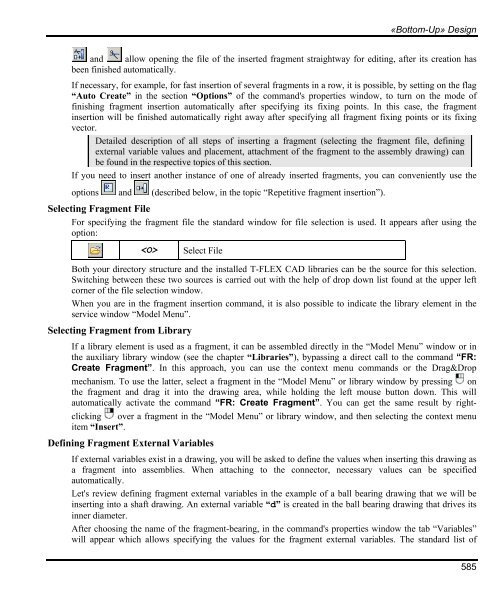
- Page 584 and 585: «Bottom-Up» Design The following
- Page 588 and 589: «Bottom-Up» Design In this case t
- Page 590 and 591: «Bottom-Up» Design 3. Upon insert
- Page 592 and 593: «Bottom-Up» Design With this type
- Page 594 and 595: «Bottom-Up» Design It is possible
- Page 596 and 597: «Bottom-Up» Design picture, other
- Page 598 and 599: «Bottom-Up» Design Section “Pre
- Page 600 and 601: Managing Fragments in Assembly Cont
- Page 602 and 603: The option brings up the dialog box
- Page 604 and 605: Editing Fragments In some cases, th
- Page 606 and 607: Editing Fragments A detail drawing
- Page 608 and 609: Editing Fragments The common variab
- Page 610 and 611: Bill of Materials Working with BOM
- Page 612 and 613: Bill of Materials Attention: the ch
- Page 614 and 615: BOM Composition Any BOM is composed
- Page 616 and 617: The icons for managing the list ele
- Page 618 and 619: Bill of Materials The table on the
- Page 620 and 621: Creating BOM on New Drawing Page or
- Page 622 and 623: Switching Between the Assembly and
- Page 624 and 625: Bill of Materials To reorder the gr
- Page 626 and 627: Bill of Materials “Groups” Tab
- Page 628 and 629: Bill of Materials Standard. Present
- Page 630 and 631: Bill of Materials Substring from en
- Page 632 and 633: Bill of Materials On the main toolb
- Page 634 and 635: To have a BOM row ignored when sett
- Page 636 and 637:
Bill of Materials If the icon is in
- Page 638 and 639:
BOM Export Bill of Materials For ex
- Page 640 and 641:
Creating and Editing BOM Prototype
- Page 642 and 643:
Creating prototype for BOM located
- Page 644 and 645:
Format Paragraph Parameters of cha
- Page 646:
Bill of Materials Save this file. T
- Page 649 and 650:
Fundamentals. Two-Dimensional Desig
- Page 651 and 652:
Fundamentals. Two-Dimensional Desig
- Page 653 and 654:
Fundamentals. Two-Dimensional Desig
- Page 655 and 656:
Fundamentals. Two-Dimensional Desig
- Page 657 and 658:
Fundamentals. Two-Dimensional Desig
- Page 659 and 660:
Fundamentals. Two-Dimensional Desig
- Page 661 and 662:
Fundamentals. Two-Dimensional Desig
- Page 663 and 664:
Fundamentals. Two-Dimensional Desig
- Page 665 and 666:
Fundamentals. Two-Dimensional Desig
- Page 667 and 668:
Fundamentals. Two-Dimensional Desig
- Page 669 and 670:
Fundamentals. Two-Dimensional Desig
- Page 671 and 672:
Fundamentals. Two-Dimensional Desig
- Page 673 and 674:
Fundamentals. Two-Dimensional Desig
- Page 675 and 676:
Fundamentals. Two-Dimensional Desig
- Page 677 and 678:
Fundamentals. Two-Dimensional Desig
- Page 679 and 680:
Fundamentals. Two-Dimensional Desig
- Page 681 and 682:
Fundamentals. Two-Dimensional Desig
- Page 683 and 684:
Fundamentals. Two-Dimensional Desig
- Page 685 and 686:
Fundamentals. Two-Dimensional Desig
- Page 687 and 688:
Fundamentals. Two-Dimensional Desig
- Page 689 and 690:
Fundamentals. Two-Dimensional Desig
- Page 691 and 692:
Fundamentals. Two-Dimensional Desig
- Page 693 and 694:
Fundamentals. Two-Dimensional Desig
- Page 695 and 696:
Fundamentals. Two-Dimensional Desig
- Page 697 and 698:
Fundamentals. Two-Dimensional Desig
- Page 699 and 700:
Fundamentals. Two-Dimensional Desig
- Page 701 and 702:
Fundamentals. Two-Dimensional Desig
- Page 703 and 704:
Fundamentals. Two-Dimensional Desig
- Page 705 and 706:
Fundamentals. Two-Dimensional Desig
- Page 707 and 708:
Fundamentals. Two-Dimensional Desig
- Page 709 and 710:
Fundamentals. Two-Dimensional Desig
- Page 711 and 712:
Fundamentals. Two-Dimensional Desig
- Page 713 and 714:
Fundamentals. Two-Dimensional Desig
- Page 715 and 716:
Fundamentals. Two-Dimensional Desig
- Page 717 and 718:
Fundamentals. Two-Dimensional Desig
- Page 719 and 720:
Fundamentals. Two-Dimensional Desig
- Page 721 and 722:
Fundamentals. Two-Dimensional Desig
- Page 723 and 724:
Fundamentals. Two-Dimensional Desig
- Page 725 and 726:
Fundamentals. Two-Dimensional Desig
- Page 727 and 728:
Fundamentals. Two-Dimensional Desig
- Page 729 and 730:
Fundamentals. Two-Dimensional Desig
- Page 731 and 732:
Fundamentals. Two-Dimensional Desig
- Page 733 and 734:
Fundamentals. Two-Dimensional Desig
- Page 735 and 736:
Fundamentals. Two-Dimensional Desig
- Page 737 and 738:
Fundamentals. Two-Dimensional Desig
- Page 739 and 740:
Fundamentals. Two-Dimensional Desig
- Page 741 and 742:
Fundamentals. Two-Dimensional Desig
- Page 743 and 744:
Fundamentals. Two-Dimensional Desig
- Page 745 and 746:
Fundamentals. Two-Dimensional Desig
- Page 747 and 748:
Fundamentals. Two-Dimensional Desig
- Page 749 and 750:
Fundamentals. Two-Dimensional Desig
- Page 751 and 752:
Fundamentals. Two-Dimensional Desig
- Page 753 and 754:
Fundamentals. Two-Dimensional Desig
- Page 755 and 756:
Fundamentals. Two-Dimensional Desig
- Page 757 and 758:
Two-dimensional design CONVERTING D
- Page 759 and 760:
Two-dimensional design Performing C
- Page 761 and 762:
Two-dimensional design 760 After co
- Page 763:
Two-dimensional design 762 Use of t