T-FLEX Parametric CAD. Fundamentals. 2D Design
T-FLEX Parametric CAD. Fundamentals. 2D Design T-FLEX Parametric CAD. Fundamentals. 2D Design
«Bottom-Up» Design As a result, two intersecting construction lines will appear in the screen. Besides, a pair of external variables will be created, x1 (x2, x3, ...) and y1 (y2, y3, ...). The parameters of the horizontal and the vertical construction lines will be given by these variables. Thus, a fixing point is produced in the drawing. When inserting this fragment in an assembly drawing, the system will ask you to specify the fixing point. If necessary, a fixing point can be defined manually. To do this, just create manually two intersecting lines, a vertical and a horizontal one, and assigne the reserved variable names to their parameters, x1 (x2, x3, ...) and y1 (y2, y3, ...), respectively. The variables must be marked as external in this case. Throughout the following description, the expression “Create first (second, …) fixing point” will imply performing all steps of a fixing point creation described above. Let's review most common techniques of creating fixing points of fragments and local coordinate systems in a drawing. Fragment with one fixing point without rotation provision Create a fixing point. After that, create all construction lines relative to the vertical and horizontal construction lines that define the fixing point. In the course of the drawing creation, do not use the lines of types “vertical” and “horizontal”; rather, use the types “parallel” and “under angle”. If you follow those rules, you'll get a drawing whose local coordinate system originates in the fixing point, and axes collinear with the X-axis and Y-axis of a drawing in which the current fragment is being inserted. Fragment with one fixing point with rotation provision Create a fixing point. Then, create a construction line passing through the node of the fixing point, at an angle to the horizontal line. Assign the slant angle of the line the variable “al”. When creating the variable, mark it as external and enter value other than 0 (entering “0” will make the lines coincide with the horizontal line on the drawing, complicating further constructions). The variable “al” will be an external variable of the drawing. Upon inserting the drawing as a fragment, the system will be asking for the value of the variable “al”. The construction line passing through the node at an angle to the horizontal line defines the X-axis of the new local coordinate system in this drawing. To create the Y-axis, make a construction line passing through the node and orthogonal to the slanted construction line that is passing at the specified angle to the horizontal line. The slanted line and the line perpendicular to it define a new local coordinate system in the drawing. All further constructions must be based on these lines. As a result, a parametric fragment will be built with one fixing point and the variable “al”, that will be defining the slant angle of the fragment coordinate system with respect to the coordinates of the assembly drawing. To make further constructions with respect to the new coordinate system easy, we recommend doing the following steps. Set the level value equal to “-1” for the vertical and horizontal lines passing through the fixing point. The lines will disappear from display as the construction lines visibility levels are defined by the range from 0 to 127 in the command “SH: Set Levels”, while these lines are assigned the level -1 and do not belong in the range. After that, call the command “ST: Set Model Status”, switch to the tab “Screen” and select the value “Visible only” in the parameter “Element selection”. By doing so, you set the drawing into the mode in which the elements will not be selectable that are not shown on the drawing. 581
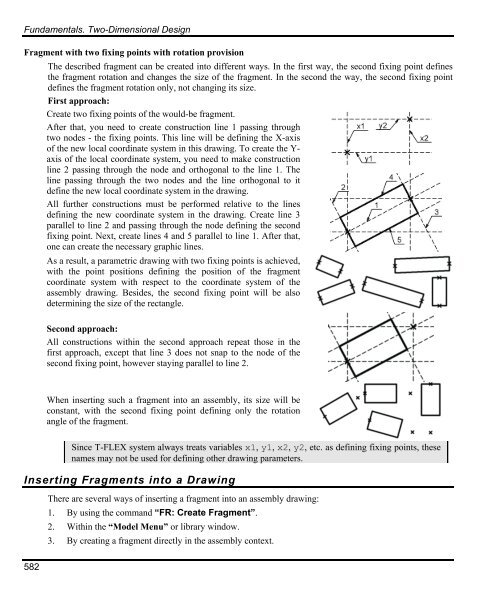
Fundamentals. Two-Dimensional Design Fragment with two fixing points with rotation provision 582 The described fragment can be created into different ways. In the first way, the second fixing point defines the fragment rotation and changes the size of the fragment. In the second the way, the second fixing point defines the fragment rotation only, not changing its size. First approach: Create two fixing points of the would-be fragment. After that, you need to create construction line 1 passing through two nodes - the fixing points. This line will be defining the X-axis of the new local coordinate system in this drawing. To create the Yaxis of the local coordinate system, you need to make construction line 2 passing through the node and orthogonal to the line 1. The line passing through the two nodes and the line orthogonal to it define the new local coordinate system in the drawing. All further constructions must be performed relative to the lines defining the new coordinate system in the drawing. Create line 3 parallel to line 2 and passing through the node defining the second fixing point. Next, create lines 4 and 5 parallel to line 1. After that, one can create the necessary graphic lines. As a result, a parametric drawing with two fixing points is achieved, with the point positions defining the position of the fragment coordinate system with respect to the coordinate system of the assembly drawing. Besides, the second fixing point will be also determining the size of the rectangle. Second approach: All constructions within the second approach repeat those in the first approach, except that line 3 does not snap to the node of the second fixing point, however staying parallel to line 2. When inserting such a fragment into an assembly, its size will be constant, with the second fixing point defining only the rotation angle of the fragment. Since T-FLEX system always treats variables x1, y1, x2, y2, etc. as defining fixing points, these names may not be used for defining other drawing parameters. Inserting Fragments into a Drawing There are several ways of inserting a fragment into an assembly drawing: 1. By using the command “FR: Create Fragment”. 2. Within the “Model Menu” or library window. 3. By creating a fragment directly in the assembly context.
- Page 532 and 533: Duplicate Keyboard Textual Menu Ico
- Page 534 and 535: Databases decides what function to
- Page 536 and 537: Control Elements. Creating User Def
- Page 538 and 539: Control Elements. Creating User Def
- Page 540 and 541: Control Elements. Creating User Def
- Page 542 and 543: Control Elements. Creating User Def
- Page 544 and 545: Control Elements. Creating User Def
- Page 546 and 547: Use of the Dialog Control Elements.
- Page 548 and 549: Parametricity of Custom Dialogs Con
- Page 550 and 551: Control Elements. Creating User Def
- Page 552 and 553: Control Elements. Creating User Def
- Page 554 and 555: Control Elements Modification Contr
- Page 556 and 557: The option calls the property windo
- Page 558 and 559: Optimization The tolerance value de
- Page 560 and 561: The example presents a kinematic sy
- Page 562 and 563: Optimization After specifying the o
- Page 564 and 565: Basic Fundamentals and Concepts of
- Page 566 and 567: Basic Fundamentals and Concepts of
- Page 568 and 569: Basic Fundamentals and Concepts of
- Page 570 and 571: Let's review hidden line removal on
- Page 572 and 573: Basic Fundamentals and Concepts of
- Page 574 and 575: List of Commands Used in Assembly D
- Page 576 and 577: «BOTTOM-UP» DESIGN «Bottom-Up»
- Page 578 and 579: «Bottom-Up» Design When creating
- Page 580 and 581: «Bottom-Up» Design Initially, a n
- Page 584 and 585: «Bottom-Up» Design The following
- Page 586 and 587: «Bottom-Up» Design and allow open
- Page 588 and 589: «Bottom-Up» Design In this case t
- Page 590 and 591: «Bottom-Up» Design 3. Upon insert
- Page 592 and 593: «Bottom-Up» Design With this type
- Page 594 and 595: «Bottom-Up» Design It is possible
- Page 596 and 597: «Bottom-Up» Design picture, other
- Page 598 and 599: «Bottom-Up» Design Section “Pre
- Page 600 and 601: Managing Fragments in Assembly Cont
- Page 602 and 603: The option brings up the dialog box
- Page 604 and 605: Editing Fragments In some cases, th
- Page 606 and 607: Editing Fragments A detail drawing
- Page 608 and 609: Editing Fragments The common variab
- Page 610 and 611: Bill of Materials Working with BOM
- Page 612 and 613: Bill of Materials Attention: the ch
- Page 614 and 615: BOM Composition Any BOM is composed
- Page 616 and 617: The icons for managing the list ele
- Page 618 and 619: Bill of Materials The table on the
- Page 620 and 621: Creating BOM on New Drawing Page or
- Page 622 and 623: Switching Between the Assembly and
- Page 624 and 625: Bill of Materials To reorder the gr
- Page 626 and 627: Bill of Materials “Groups” Tab
- Page 628 and 629: Bill of Materials Standard. Present
- Page 630 and 631: Bill of Materials Substring from en
<strong>Fundamentals</strong>. Two-Dimensional <strong>Design</strong><br />
Fragment with two fixing points with rotation provision<br />
582<br />
The described fragment can be created into different ways. In the first way, the second fixing point defines<br />
the fragment rotation and changes the size of the fragment. In the second the way, the second fixing point<br />
defines the fragment rotation only, not changing its size.<br />
First approach:<br />
Create two fixing points of the would-be fragment.<br />
After that, you need to create construction line 1 passing through<br />
two nodes - the fixing points. This line will be defining the X-axis<br />
of the new local coordinate system in this drawing. To create the Yaxis<br />
of the local coordinate system, you need to make construction<br />
line 2 passing through the node and orthogonal to the line 1. The<br />
line passing through the two nodes and the line orthogonal to it<br />
define the new local coordinate system in the drawing.<br />
All further constructions must be performed relative to the lines<br />
defining the new coordinate system in the drawing. Create line 3<br />
parallel to line 2 and passing through the node defining the second<br />
fixing point. Next, create lines 4 and 5 parallel to line 1. After that,<br />
one can create the necessary graphic lines.<br />
As a result, a parametric drawing with two fixing points is achieved,<br />
with the point positions defining the position of the fragment<br />
coordinate system with respect to the coordinate system of the<br />
assembly drawing. Besides, the second fixing point will be also<br />
determining the size of the rectangle.<br />
Second approach:<br />
All constructions within the second approach repeat those in the<br />
first approach, except that line 3 does not snap to the node of the<br />
second fixing point, however staying parallel to line 2.<br />
When inserting such a fragment into an assembly, its size will be<br />
constant, with the second fixing point defining only the rotation<br />
angle of the fragment.<br />
Since T-<strong>FLEX</strong> system always treats variables x1, y1, x2, y2, etc. as defining fixing points, these<br />
names may not be used for defining other drawing parameters.<br />
Inserting Fragments into a Drawing<br />
There are several ways of inserting a fragment into an assembly drawing:<br />
1. By using the command “FR: Create Fragment”.<br />
2. Within the “Model Menu” or library window.<br />
3. By creating a fragment directly in the assembly context.


