T-FLEX Parametric CAD. Fundamentals. 2D Design
T-FLEX Parametric CAD. Fundamentals. 2D Design T-FLEX Parametric CAD. Fundamentals. 2D Design
«Bottom-Up» Design Initially, a new connector does not contain any variables. At the time of creation, the user normally already knows the purpose of creating this connector and, in particular, what parameters of the connector fragments to control with it. If, for example, we create a connector on the axis of a shaft, we will be connecting to it the fragments of parts to be mounted on the shaft. Therefore, we need to pass the shaft diameter value to the fragment being connected (say, a ball bearing). To create a new variable in the connector , press the button [Add]. In the coming up window, define the name of the connector variable and its expression. The name of the connector value is used subsequently upon attaching another fragment to the given connector. The name of the external variable of the fragment may not coincide with the value of the connector. At the moment of attaching the system uses a special parameter of the fragment external variable called «Connector values» (see the chapter «Variables» for details). If in the list of values of the external variable connector the name coinciding with the value stored in the connector, to which the fragment is being attached, will be found, then the value for the external variable will be automatically read from the connector. Link with the connector will be retained. Also, when attaching to the connector there is a possibility to manually link any fragment external variable directly with one of the connector values (see below “Specifying values of fragment external variables”). The number (or the text in quotation marks for a text variable), expression or the name of the current document variable can be put into the field “Expression”. In our example, the value of the diameter, which is driven by a certain variable (for example, ‘D’) in the shaft model, has to be passed to other fragments. When creating the named value for the connector, it is possible to assign the name ‘Diameter’, and put the variable ‘D’ into the expression field. When creating the ball bearing model, in the properties for the variable driving the mounting diameter, it is necessary to specify the new value of the connector with the name ‘Diameter’. The tab “Common” allows defining basic properties of a connector as an auxiliary drawing object – name, level, layer and color. Besides, a special box in this tab tracks information about the number of connections to this connector (if the dialog of the connector properties is open directly in the assembly drawing). Defining associated elements for connector To define associations of graphic lines with a connector, use the option in the automenu: Set Snap Elements Upon selecting the option, the system enters the mode of selecting lines in the drawing that will activate the connector once pointed at by the mouse. To add elements to the connector, select those by the mouse in the drawing window. The selected elements are included into the list of associated elements in the properties window. 579
Fundamentals. Two-Dimensional Design Insertion rules 580 So-called «insertion rules» can be additionally defined for a connector. These are additional transformations of translation and rotation with respect to the coordinate axes of the connector which the system will prompt a user to carry out when attaching a fragment to a given connector. For example, when attaching a nut to the bolt connector, in practice it is always required to specify additional translation of the nut along the axis of the bolt. That is why when designing the bolt model, in the insertion rules for the bolt connector the necessity of translational motion along the X-axis of the connector has to be specified. Fixing Points A fixing point is created as an intersection of a vertical and horizontal lines, whose parameters are defined by variables with reserved names. The variables reserved for the vertical lines are: x1, x2, x3, x4, x5, x6, x7, x8, x9. Those for the horizontal lines are: y1, y2, y3, y4, y5, y6, y7, y8, y9. The numeric postfix of X and Y corresponds to the number of the fixing point and must match between the vertical and horizontal lines that define one fixing point. Up to nine fixing points are supported in a drawing. An example of fragment with three fixing points (a transistor) When using the fragment fixing method based on fixing points, one has to determine the necessary fixing points before creating the drawing. All the rest of the drawing elements must be created relative to the lines defining those points. For example, if we want to use a circle as a fragment, that we could the later place in various locations in the drawings, we should first create a horizontal and the vertical line, and only after that the circle at their intersection point. Fixing point creation Fixing points can be created automatically, using the option of the command “L: Construct Line”. Upon calling the option, move the pointer to the desired position and press (, , ...) or use the automenu icon . When creating a point by option , a number will be attached to the pointer, indicating the order number of the fixing point being created.
- Page 530 and 531: Save Database As External Keyboard
- Page 532 and 533: Duplicate Keyboard Textual Menu Ico
- Page 534 and 535: Databases decides what function to
- Page 536 and 537: Control Elements. Creating User Def
- Page 538 and 539: Control Elements. Creating User Def
- Page 540 and 541: Control Elements. Creating User Def
- Page 542 and 543: Control Elements. Creating User Def
- Page 544 and 545: Control Elements. Creating User Def
- Page 546 and 547: Use of the Dialog Control Elements.
- Page 548 and 549: Parametricity of Custom Dialogs Con
- Page 550 and 551: Control Elements. Creating User Def
- Page 552 and 553: Control Elements. Creating User Def
- Page 554 and 555: Control Elements Modification Contr
- Page 556 and 557: The option calls the property windo
- Page 558 and 559: Optimization The tolerance value de
- Page 560 and 561: The example presents a kinematic sy
- Page 562 and 563: Optimization After specifying the o
- Page 564 and 565: Basic Fundamentals and Concepts of
- Page 566 and 567: Basic Fundamentals and Concepts of
- Page 568 and 569: Basic Fundamentals and Concepts of
- Page 570 and 571: Let's review hidden line removal on
- Page 572 and 573: Basic Fundamentals and Concepts of
- Page 574 and 575: List of Commands Used in Assembly D
- Page 576 and 577: «BOTTOM-UP» DESIGN «Bottom-Up»
- Page 578 and 579: «Bottom-Up» Design When creating
- Page 582 and 583: «Bottom-Up» Design As a result, t
- Page 584 and 585: «Bottom-Up» Design The following
- Page 586 and 587: «Bottom-Up» Design and allow open
- Page 588 and 589: «Bottom-Up» Design In this case t
- Page 590 and 591: «Bottom-Up» Design 3. Upon insert
- Page 592 and 593: «Bottom-Up» Design With this type
- Page 594 and 595: «Bottom-Up» Design It is possible
- Page 596 and 597: «Bottom-Up» Design picture, other
- Page 598 and 599: «Bottom-Up» Design Section “Pre
- Page 600 and 601: Managing Fragments in Assembly Cont
- Page 602 and 603: The option brings up the dialog box
- Page 604 and 605: Editing Fragments In some cases, th
- Page 606 and 607: Editing Fragments A detail drawing
- Page 608 and 609: Editing Fragments The common variab
- Page 610 and 611: Bill of Materials Working with BOM
- Page 612 and 613: Bill of Materials Attention: the ch
- Page 614 and 615: BOM Composition Any BOM is composed
- Page 616 and 617: The icons for managing the list ele
- Page 618 and 619: Bill of Materials The table on the
- Page 620 and 621: Creating BOM on New Drawing Page or
- Page 622 and 623: Switching Between the Assembly and
- Page 624 and 625: Bill of Materials To reorder the gr
- Page 626 and 627: Bill of Materials “Groups” Tab
- Page 628 and 629: Bill of Materials Standard. Present
<strong>Fundamentals</strong>. Two-Dimensional <strong>Design</strong><br />
Insertion rules<br />
580<br />
So-called «insertion rules» can be additionally defined for a connector. These are additional transformations<br />
of translation and rotation with respect to the coordinate axes of the connector which the system will prompt<br />
a user to carry out when attaching a fragment to a given connector. For example, when attaching a nut to the<br />
bolt connector, in practice it is always required to specify additional translation of the nut along the axis of<br />
the bolt. That is why when designing the bolt model, in the insertion rules for the bolt connector the necessity<br />
of translational motion along the X-axis of the connector has to be specified.<br />
Fixing Points<br />
A fixing point is created as an intersection of a vertical and horizontal lines, whose parameters are defined<br />
by variables with reserved names.<br />
The variables reserved for the vertical lines are: x1, x2, x3, x4, x5, x6, x7, x8, x9.<br />
Those for the horizontal lines are: y1, y2, y3, y4, y5, y6, y7, y8, y9.<br />
The numeric postfix of X and Y corresponds to the number of the fixing point and must match between the<br />
vertical and horizontal lines that define one fixing point. Up to nine fixing points are supported in a drawing.<br />
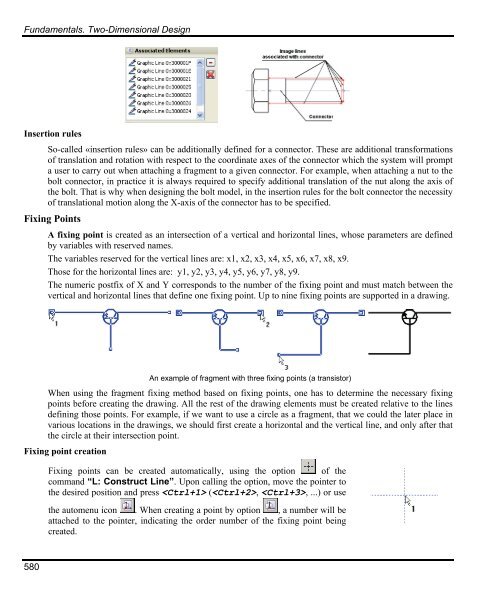
An example of fragment with three fixing points (a transistor)<br />
When using the fragment fixing method based on fixing points, one has to determine the necessary fixing<br />
points before creating the drawing. All the rest of the drawing elements must be created relative to the lines<br />
defining those points. For example, if we want to use a circle as a fragment, that we could the later place in<br />
various locations in the drawings, we should first create a horizontal and the vertical line, and only after that<br />
the circle at their intersection point.<br />
Fixing point creation<br />
Fixing points can be created automatically, using the option of the<br />
command “L: Construct Line”. Upon calling the option, move the pointer to<br />
the desired position and press (, , ...) or use<br />
the automenu icon . When creating a point by option , a number will be<br />
attached to the pointer, indicating the order number of the fixing point being<br />
created.


