T-FLEX Parametric CAD. Fundamentals. 2D Design
T-FLEX Parametric CAD. Fundamentals. 2D Design T-FLEX Parametric CAD. Fundamentals. 2D Design
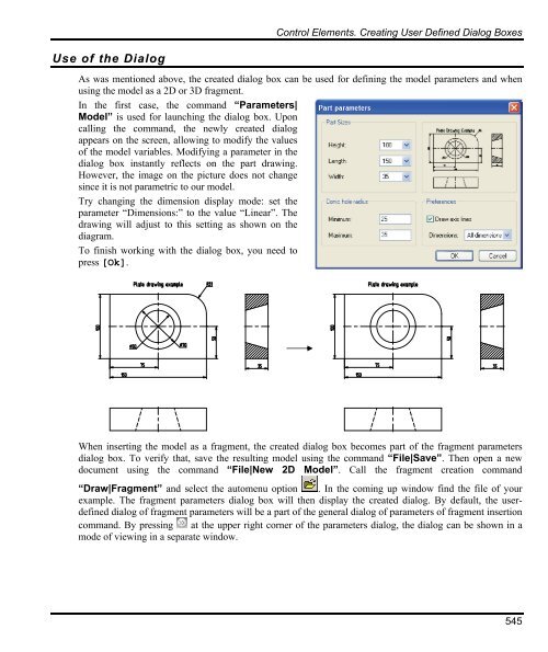
Use of the Dialog Control Elements. Creating User Defined Dialog Boxes As was mentioned above, the created dialog box can be used for defining the model parameters and when using the model as a 2D or 3D fragment. In the first case, the command “Parameters| Model” is used for launching the dialog box. Upon calling the command, the newly created dialog appears on the screen, allowing to modify the values of the model variables. Modifying a parameter in the dialog box instantly reflects on the part drawing. However, the image on the picture does not change since it is not parametric to our model. Try changing the dimension display mode: set the parameter “Dimensions:” to the value “Linear”. The drawing will adjust to this setting as shown on the diagram. To finish working with the dialog box, you need to press [Ok]. When inserting the model as a fragment, the created dialog box becomes part of the fragment parameters dialog box. To verify that, save the resulting model using the command “File|Save”. Then open a new document using the command “File|New 2D Model”. Call the fragment creation command “Draw|Fragment” and select the automenu option . In the coming up window find the file of your example. The fragment parameters dialog box will then display the created dialog. By default, the userdefined dialog of fragment parameters will be a part of the general dialog of parameters of fragment insertion command. By pressing at the upper right corner of the parameters dialog, the dialog can be shown in a mode of viewing in a separate window. 545
Fundamentals. Two-Dimensional Design 546 Note that the preview pane now appears in the dialog box, screening out the picture. All changes done to the model parameters using the dialog controls will be reflected in the preview pane. The preview pane also displays the selected drawing page and the fragment fixing vectors present in the model. The control elements that make up the dialog can be used for modifying the model external variables directly in the 2D window, without calling the command “Parameters|Model” or “Draw|Fragment”. In this way, working with the dialog page is similar to working with the actual dialog box when the latter comes up on the screen. Thus, upon clicking on the “Button” control, all functions defined for this control elements are activated from the dialog page. Upon clicking on the elements “Edit Box” and “Combo Box”, one can manually define or select from the list a new variable value. Clicking changes the states of the “Radio Button” and “Check Box” control elements. To finish inputting changes, you can press , or over any empty area on the dialog page. The entered changes can be canceled by pressing , or . In this case, a confirmation window will appear, double-checking about the cancellation. A “Combo Box” control allows an additional manipulation. If it is bound to a variable whose predefined list is based on a file, then you can modify this list directly in the dialog page by turning on the “Editable” parameter. To do this, point the mouse to the input box of this control and access the context menu. Commands will be provided in the context menu for modifying the list of predefined values of the variable. Upon selecting the command “Add to list”, the value entered in the input box is added to the list of values for this variable. Selecting the command “Edit List” brings up the “Value List of Variable” dialog box, that allows editing the existing list.
- Page 496 and 497: Variables -23 % -5 = -3 23 % -5 = 3
- Page 498 and 499: Variables The angle arguments of tr
- Page 500 and 501: Variables TWORD(“string”, N) Ge
- Page 502 and 503: Variables The detailed description
- Page 504 and 505: LTOT ( 120.34567, 0.001, 1, 5 ) ret
- Page 506 and 507: for text: “WIDTH” - the text wi
- Page 508 and 509: for loop: “AxisX”, “AxisY”,
- Page 510 and 511: Variables One more additional relat
- Page 512 and 513: Variables BOMPAGES - returns the to
- Page 514 and 515: Measure Elements and Relations betw
- Page 516 and 517: Additional Methods of Calling Comma
- Page 518 and 519: Hatches: Text: 3D objects “AREA
- Page 520 and 521: Loops: Measure Elements and Relatio
- Page 522 and 523: GLOBAL VARIABLES Global Variables A
- Page 524 and 525: DATABASES Databases Databases provi
- Page 526 and 527: Databases Name of the field. Define
- Page 528 and 529: Databases argument_3 - the search o
- Page 530 and 531: Save Database As External Keyboard
- Page 532 and 533: Duplicate Keyboard Textual Menu Ico
- Page 534 and 535: Databases decides what function to
- Page 536 and 537: Control Elements. Creating User Def
- Page 538 and 539: Control Elements. Creating User Def
- Page 540 and 541: Control Elements. Creating User Def
- Page 542 and 543: Control Elements. Creating User Def
- Page 544 and 545: Control Elements. Creating User Def
- Page 548 and 549: Parametricity of Custom Dialogs Con
- Page 550 and 551: Control Elements. Creating User Def
- Page 552 and 553: Control Elements. Creating User Def
- Page 554 and 555: Control Elements Modification Contr
- Page 556 and 557: The option calls the property windo
- Page 558 and 559: Optimization The tolerance value de
- Page 560 and 561: The example presents a kinematic sy
- Page 562 and 563: Optimization After specifying the o
- Page 564 and 565: Basic Fundamentals and Concepts of
- Page 566 and 567: Basic Fundamentals and Concepts of
- Page 568 and 569: Basic Fundamentals and Concepts of
- Page 570 and 571: Let's review hidden line removal on
- Page 572 and 573: Basic Fundamentals and Concepts of
- Page 574 and 575: List of Commands Used in Assembly D
- Page 576 and 577: «BOTTOM-UP» DESIGN «Bottom-Up»
- Page 578 and 579: «Bottom-Up» Design When creating
- Page 580 and 581: «Bottom-Up» Design Initially, a n
- Page 582 and 583: «Bottom-Up» Design As a result, t
- Page 584 and 585: «Bottom-Up» Design The following
- Page 586 and 587: «Bottom-Up» Design and allow open
- Page 588 and 589: «Bottom-Up» Design In this case t
- Page 590 and 591: «Bottom-Up» Design 3. Upon insert
- Page 592 and 593: «Bottom-Up» Design With this type
- Page 594 and 595: «Bottom-Up» Design It is possible
Use of the Dialog<br />
Control Elements. Creating User Defined Dialog Boxes<br />
As was mentioned above, the created dialog box can be used for defining the model parameters and when<br />
using the model as a <strong>2D</strong> or 3D fragment.<br />
In the first case, the command “Parameters|<br />
Model” is used for launching the dialog box. Upon<br />
calling the command, the newly created dialog<br />
appears on the screen, allowing to modify the values<br />
of the model variables. Modifying a parameter in the<br />
dialog box instantly reflects on the part drawing.<br />
However, the image on the picture does not change<br />
since it is not parametric to our model.<br />
Try changing the dimension display mode: set the<br />
parameter “Dimensions:” to the value “Linear”. The<br />
drawing will adjust to this setting as shown on the<br />
diagram.<br />
To finish working with the dialog box, you need to<br />
press [Ok].<br />
When inserting the model as a fragment, the created dialog box becomes part of the fragment parameters<br />
dialog box. To verify that, save the resulting model using the command “File|Save”. Then open a new<br />
document using the command “File|New <strong>2D</strong> Model”. Call the fragment creation command<br />
“Draw|Fragment” and select the automenu option . In the coming up window find the file of your<br />
example. The fragment parameters dialog box will then display the created dialog. By default, the userdefined<br />
dialog of fragment parameters will be a part of the general dialog of parameters of fragment insertion<br />
command. By pressing at the upper right corner of the parameters dialog, the dialog can be shown in a<br />
mode of viewing in a separate window.<br />
545


