T-FLEX Parametric CAD. Fundamentals. 2D Design
T-FLEX Parametric CAD. Fundamentals. 2D Design T-FLEX Parametric CAD. Fundamentals. 2D Design
Roughness Symbols The roughness can be instantly placed in the absolute coordinates at the pointer position by clicking . An exact value of coordinates can be defined in the command's properties window (the section “Coordinates”). The way of attaching the created roughness is determined by the status of the option . This option contains a drop down list with the following choices: Roughness without leader jog Roughness with leader jog Attach to the sign point To attach a roughness symbol to a construction or graphic line (ellipse, spline, path or function), use the respective option (, ). The graphic pointer must be over the desired line when using the option. The intended construction entity must have at least one node on it. In this way, the roughness being created is attached to the entity and the nearest node on this construction entity. A leader line will be created by default from the node to the roughness symbol (you can cancel the leader line creation in the command's properties window). L With the object snapping engaged, to select an attachment element you just need to move the pointer over the desired element. As the element pre-highlights and the pointer changes its shape, indicating snapping to the element, click . In complicated configurations, you can use the element selection options for precise element selection. Upon selecting the construction or graphic entity (ellipse, spline, path or function), a roughness symbol starts rubberbanding with the pointer. To complete the creation, point the mouse to the desired position of the roughness symbol (the distance from the node to which the roughness being created is attached) and click . A precise position of the roughness on a construction or graphic line can be defined in the command's properties window. For attaching to a node, select the desired node by pressing the key . N When selecting a node, the roughness can be created in two modes: with an offset from the node and without an offset. By default, the mode of snapping to the node without an offset is used. This is indicated by the enabled option in the command automenu. In this case, you just need to point at a node and click . To set the mode of snapping to a node with an offset, disable the option . In this case, after selecting the snap node you will need to specify an offset relative to the node for the roughness. This can be done by in the drawing window or by entering the exact offset value in the command's properties window. A roughness symbol can be attached to a circle (the option ). 389
Fundamentals. Two-Dimensional Design 390 The dimension is selected by the key . С D A roughness can also be attached to graphic lines. As the pointer approaches a graphic line, the entity is pre-highlighted due to the object snapping. If the roughness symbol is placed beyond the graphic line limits, then by default a leader is created along the graphic line extension up to the roughness symbol (the leader creation can be disabled in the roughness parameters). To undo element selection (line, node, circle or dimension), and, thus, to cancel the attachment relation, use the option . To cancel the last action (for example, to cancel the leader start attachment), use the key or right click . Roughness parameters are defined in the command's properties window prior to specifying the roughness position on the drawing. Besides that, you can enter the exact position of the roughness snap point in the properties window. Option will take parameters of roughness symbol from already existing roughness element. See chapter “Dimensions” for more details on this option.
- Page 339 and 340: Fundamentals. Two-Dimensional Desig
- Page 341 and 342: Fundamentals. Two-Dimensional Desig
- Page 343 and 344: Fundamentals. Two-Dimensional Desig
- Page 345 and 346: Fundamentals. Two-Dimensional Desig
- Page 347 and 348: Fundamentals. Two-Dimensional Desig
- Page 349 and 350: Fundamentals. Two-Dimensional Desig
- Page 351 and 352: Fundamentals. Two-Dimensional Desig
- Page 353 and 354: Fundamentals. Two-Dimensional Desig
- Page 355 and 356: Fundamentals. Two-Dimensional Desig
- Page 357 and 358: Fundamentals. Two-Dimensional Desig
- Page 359 and 360: Fundamentals. Two-Dimensional Desig
- Page 361 and 362: Fundamentals. Two-Dimensional Desig
- Page 363 and 364: Fundamentals. Two-Dimensional Desig
- Page 365 and 366: Fundamentals. Two-Dimensional Desig
- Page 367 and 368: Fundamentals. Two-Dimensional Desig
- Page 369 and 370: Fundamentals. Two-Dimensional Desig
- Page 371 and 372: Fundamentals. Two-Dimensional Desig
- Page 373 and 374: Fundamentals. Two-Dimensional Desig
- Page 375 and 376: Fundamentals. Two-Dimensional Desig
- Page 377 and 378: Fundamentals. Two-Dimensional Desig
- Page 379 and 380: Fundamentals. Two-Dimensional Desig
- Page 381 and 382: Fundamentals. Two-Dimensional Desig
- Page 383 and 384: Fundamentals. Two-Dimensional Desig
- Page 385 and 386: Fundamentals. Two-Dimensional Desig
- Page 387 and 388: Fundamentals. Two-Dimensional Desig
- Page 389: Fundamentals. Two-Dimensional Desig
- Page 393 and 394: Fundamentals. Two-Dimensional Desig
- Page 395 and 396: Fundamentals. Two-Dimensional Desig
- Page 397 and 398: Fundamentals. Two-Dimensional Desig
- Page 399 and 400: Fundamentals. Two-Dimensional Desig
- Page 401 and 402: Fundamentals. Two-Dimensional Desig
- Page 403 and 404: Fundamentals. Two-Dimensional Desig
- Page 405 and 406: Fundamentals. Two-Dimensional Desig
- Page 407 and 408: Fundamentals. Two-Dimensional Desig
- Page 409 and 410: Fundamentals. Two-Dimensional Desig
- Page 411 and 412: Fundamentals. Two-Dimensional Desig
- Page 413 and 414: Fundamentals. Two-Dimensional Desig
- Page 415 and 416: Fundamentals. Two-Dimensional Desig
- Page 417 and 418: Fundamentals. Two-Dimensional Desig
- Page 419 and 420: Fundamentals. Two-Dimensional Desig
- Page 421 and 422: Fundamentals. Two-Dimensional Desig
- Page 423 and 424: Fundamentals. Two-Dimensional Desig
- Page 425 and 426: Fundamentals. Two-Dimensional Desig
- Page 427 and 428: Fundamentals. Two-Dimensional Desig
- Page 429 and 430: Fundamentals. Two-Dimensional Desig
- Page 431 and 432: Fundamentals. Two-Dimensional Desig
- Page 434 and 435: Drawing Editing Moving and Copying
- Page 436 and 437: “Edit|Move|Rotate” “Edit|Mov
- Page 438 and 439: Moving and Copying Drawing Elements
Roughness Symbols<br />
The roughness can be instantly placed in the absolute coordinates at the pointer position by clicking . An<br />
exact value of coordinates can be defined in the command's properties window (the section “Coordinates”).<br />
The way of attaching the created roughness is determined by the status of the option . This option<br />
contains a drop down list with the following choices:<br />
Roughness without leader jog<br />
Roughness with leader jog<br />
Attach to the sign point<br />
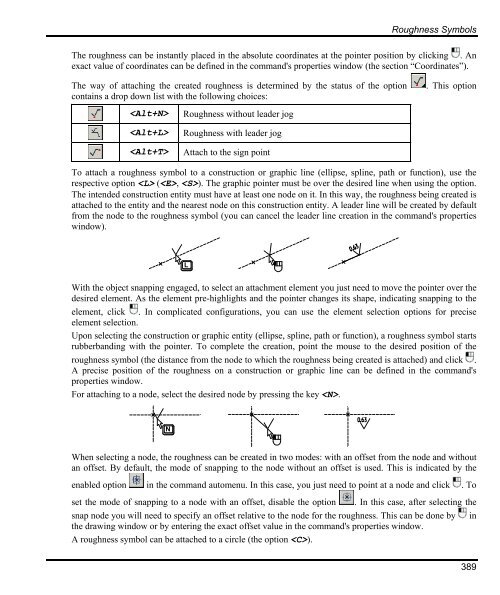
To attach a roughness symbol to a construction or graphic line (ellipse, spline, path or function), use the<br />
respective option (, ). The graphic pointer must be over the desired line when using the option.<br />
The intended construction entity must have at least one node on it. In this way, the roughness being created is<br />
attached to the entity and the nearest node on this construction entity. A leader line will be created by default<br />
from the node to the roughness symbol (you can cancel the leader line creation in the command's properties<br />
window).<br />
L<br />
With the object snapping engaged, to select an attachment element you just need to move the pointer over the<br />
desired element. As the element pre-highlights and the pointer changes its shape, indicating snapping to the<br />
element, click . In complicated configurations, you can use the element selection options for precise<br />
element selection.<br />
Upon selecting the construction or graphic entity (ellipse, spline, path or function), a roughness symbol starts<br />
rubberbanding with the pointer. To complete the creation, point the mouse to the desired position of the<br />
roughness symbol (the distance from the node to which the roughness being created is attached) and click .<br />
A precise position of the roughness on a construction or graphic line can be defined in the command's<br />
properties window.<br />
For attaching to a node, select the desired node by pressing the key .<br />
N<br />
When selecting a node, the roughness can be created in two modes: with an offset from the node and without<br />
an offset. By default, the mode of snapping to the node without an offset is used. This is indicated by the<br />
enabled option in the command automenu. In this case, you just need to point at a node and click . To<br />
set the mode of snapping to a node with an offset, disable the option . In this case, after selecting the<br />
snap node you will need to specify an offset relative to the node for the roughness. This can be done by in<br />
the drawing window or by entering the exact offset value in the command's properties window.<br />
A roughness symbol can be attached to a circle (the option ).<br />
389


