Ultrasonic Distance Measurement with the MSP430 (Rev. A)
Ultrasonic Distance Measurement with the MSP430 (Rev. A)
Ultrasonic Distance Measurement with the MSP430 (Rev. A)

You also want an ePaper? Increase the reach of your titles
YUMPU automatically turns print PDFs into web optimized ePapers that Google loves.
Application Report<br />
SLAA136A - October 2001<br />
<strong>Ultrasonic</strong> <strong>Distance</strong> <strong>Measurement</strong> With <strong>the</strong> <strong>MSP430</strong><br />
Murugavel Raju Mixed Signal Processors<br />
ABSTRACT<br />
This application report describes a distance-measuring system based on ultrasonic sound<br />
utilizing <strong>the</strong> <strong>MSP430</strong>F413 ultralow-power microcontroller. The system transmits a burst of<br />
ultrasonic sound waves towards <strong>the</strong> subject and <strong>the</strong>n receives <strong>the</strong> corresponding echo. The<br />
<strong>MSP430</strong> integrated analog comparator Comparator_A is used to detect <strong>the</strong> arrival of <strong>the</strong><br />
echo to <strong>the</strong> system. The time taken for <strong>the</strong> ultrasonic burst to travel <strong>the</strong> distance from <strong>the</strong><br />
system to <strong>the</strong> subject and back to <strong>the</strong> system is accurately measured by <strong>the</strong> <strong>MSP430</strong>.<br />
Assuming <strong>the</strong> speed of sound in air at room temperature to be 1100 ft/s, <strong>the</strong> <strong>MSP430</strong><br />
computes <strong>the</strong> distance between <strong>the</strong> system and <strong>the</strong> subject and displays it using a two-digit<br />
static LCD driven by its integrated LCD driver. The distance is displayed in inches <strong>with</strong> an<br />
accuracy of ±1 inch. The minimum distance that this system can measure is eight inches and<br />
is limited by <strong>the</strong> transmitter’s transducer settling-time. The maximum distance that can be<br />
measured is ninety-nine inches. The amplitude of <strong>the</strong> echo depends on <strong>the</strong> reflecting<br />
material, shape, and size. Sound-absorbing targets such as carpets and reflecting surfaces<br />
less than two square feet in area reflect poorly. The maximum measurable range is lower for<br />
such subjects. If <strong>the</strong> amplitude of <strong>the</strong> echo received by <strong>the</strong> system is so low that it is not<br />
detectable by <strong>the</strong> Comparator_A, <strong>the</strong> system goes out of range. This is indicated by<br />
displaying <strong>the</strong> error message E.<br />
1 Theory of Operation<br />
Contents<br />
. . . . . . . . . . . . . . . . . . . . . . . . . . . . . . . . . . . . . . . . . . . . . . . . . . . . . . . . . . . . . . . . . 2<br />
2 Circuit Description . . . . . . . . . . . . . . . . . . . . . . . . . . . . . . . . . . . . . . . . . . . . . . . . . . . . . . . . . . . . . . . . . . . 2<br />
3 Software <strong>Ultrasonic</strong>.s43 . . . . . . . . . . . . . . . . . . . . . . . . . . . . . . . . . . . . . . . . . . . . . . . . . . . . . . . . . . . . . . 6<br />
3.1 Init_Device . . . . . . . . . . . . . . . . . . . . . . . . . . . . . . . . . . . . . . . . . . . . . . . . . . . . . . . . . . . . . . . . . . . . . . 6<br />
3.2 Mainloop . . . . . . . . . . . . . . . . . . . . . . . . . . . . . . . . . . . . . . . . . . . . . . . . . . . . . . . . . . . . . . . . . . . . . . . . 6<br />
3.3 Math_calc . . . . . . . . . . . . . . . . . . . . . . . . . . . . . . . . . . . . . . . . . . . . . . . . . . . . . . . . . . . . . . . . . . . . . . . 7<br />
3.4 BT_ISR . . . . . . . . . . . . . . . . . . . . . . . . . . . . . . . . . . . . . . . . . . . . . . . . . . . . . . . . . . . . . . . . . . . . . . . . . 7<br />
3.5 Display . . . . . . . . . . . . . . . . . . . . . . . . . . . . . . . . . . . . . . . . . . . . . . . . . . . . . . . . . . . . . . . . . . . . . . . . . . 7<br />
3.6 Delay . . . . . . . . . . . . . . . . . . . . . . . . . . . . . . . . . . . . . . . . . . . . . . . . . . . . . . . . . . . . . . . . . . . . . . . . . . . 7<br />
4 Conclusion . . . . . . . . . . . . . . . . . . . . . . . . . . . . . . . . . . . . . . . . . . . . . . . . . . . . . . . . . . . . . . . . . . . . . . . . . . 7<br />
5 References . . . . . . . . . . . . . . . . . . . . . . . . . . . . . . . . . . . . . . . . . . . . . . . . . . . . . . . . . . . . . . . . . . . . . . . . . . 8<br />
A Programming Code . . . . . . . . . . . . . . . . . . . . . . . . . . . . . . . . . . . . . . . . . . . . . . . . . . . . . . . . . . . . . . . . . . 9<br />
List of Figures<br />
1 Circuit Schematic . . . . . . . . . . . . . . . . . . . . . . . . . . . . . . . . . . . . . . . . . . . . . . . . . . . . . . . . . . . . . . . . . . . . . . . 4<br />
2 Oscilloscope Trace of Transmitter’s 40-kHz Burst . . . . . . . . . . . . . . . . . . . . . . . . . . . . . . . . . . . . . . . . . . . 5<br />
3 Oscilloscope Trace for One <strong>Measurement</strong> Cycle . . . . . . . . . . . . . . . . . . . . . . . . . . . . . . . . . . . . . . . . . . . .<br />
5<br />
1
SLAA136A<br />
1 Theory of Operation<br />
This application is based upon <strong>the</strong> reflection of sound waves. Sound waves are defined as<br />
longitudinal pressure waves in <strong>the</strong> medium in which <strong>the</strong>y are travelling. Subjects whose<br />
dimensions are larger than <strong>the</strong> wavelength of <strong>the</strong> impinging sound waves reflect <strong>the</strong>m; <strong>the</strong><br />
reflected waves are called <strong>the</strong> echo. If <strong>the</strong> speed of sound in <strong>the</strong> medium is known and <strong>the</strong> time<br />
taken for <strong>the</strong> sound waves to travel <strong>the</strong> distance from <strong>the</strong> source to <strong>the</strong> subject and back to <strong>the</strong><br />
source is measured, <strong>the</strong> distance from <strong>the</strong> source to <strong>the</strong> subject can be computed accurately.<br />
This is <strong>the</strong> measurement principle of this application. Here <strong>the</strong> medium for <strong>the</strong> sound waves is<br />
air, and <strong>the</strong> sound waves used are ultrasonic, since it is inaudible to humans.<br />
Assuming that <strong>the</strong> speed of sound in air is 1100 feet/second at room temperature and that <strong>the</strong><br />
measured time taken for <strong>the</strong> sound waves to travel <strong>the</strong> distance from <strong>the</strong> source to <strong>the</strong> subject<br />
and back to <strong>the</strong> source is t seconds, <strong>the</strong> distance d is computed by <strong>the</strong> formula d=1100 X 12 X t<br />
inches. Since <strong>the</strong> sound waves travel twice <strong>the</strong> distance between <strong>the</strong> source and <strong>the</strong> subject, <strong>the</strong><br />
actual distance between <strong>the</strong> source and <strong>the</strong> subject will be d/2.<br />
2 Circuit Description<br />
The devices used to transmit and receive <strong>the</strong> ultrasonic sound waves in this application are<br />
40-kHz ceramic ultrasonic transducers. The <strong>MSP430</strong> drives <strong>the</strong> transmitter transducer <strong>with</strong> a<br />
12-cycle burst of 40-kHz square-wave signal derived from <strong>the</strong> crystal oscillator, and <strong>the</strong> receiver<br />
transducer receives <strong>the</strong> echo. The Timer_A in <strong>the</strong> <strong>MSP430</strong> is configured to count <strong>the</strong> 40-kHz<br />
crystal frequency such that <strong>the</strong> time measurement resolution is 25 µs, which is more than<br />
adequate for this application. The measurement time base is very stable as it is derived from a<br />
quartz-crystal oscillator. The echo received by <strong>the</strong> receiver transducer is amplified by an<br />
operational amplifier and <strong>the</strong> amplified output is fed to <strong>the</strong> Comparator_A input. The<br />
Comparator_A senses <strong>the</strong> presence of <strong>the</strong> echo signal at its input and triggers a capture of<br />
Timer_A count value to capture compare register CCR1. The capture is done exactly at <strong>the</strong><br />
instant <strong>the</strong> echo arrives at <strong>the</strong> system. The captured count is <strong>the</strong> measure of <strong>the</strong> time taken for<br />
<strong>the</strong> ultrasonic burst to travel <strong>the</strong> distance from <strong>the</strong> system to <strong>the</strong> subject and back to <strong>the</strong> system.<br />
The distance in inches from <strong>the</strong> system to <strong>the</strong> subject is computed by <strong>the</strong> <strong>MSP430</strong> using this<br />
measured time and displayed on a two-digit static LCD. Immediately after updating <strong>the</strong> display,<br />
<strong>the</strong> <strong>MSP430</strong> goes to LPM3 sleep mode to save power. The Basic Timer1 is programmed to<br />
interrupt <strong>the</strong> <strong>MSP430</strong> every 205 milliseconds. The interrupt signal from <strong>the</strong> Basic Timer1 wakes<br />
up <strong>the</strong> <strong>MSP430</strong> to repeat <strong>the</strong> measurement cycle and update <strong>the</strong> display.<br />
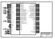
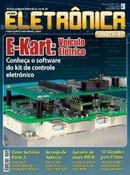
Figure 1 shows <strong>the</strong> circuit schematic diagram of this application. The <strong>MSP430</strong>F413 (U1) is <strong>the</strong><br />
core of this system. Reference [1] is <strong>the</strong> data sheet for this device. LCD1 is a two-digit<br />
low-voltage static LCD driven by <strong>the</strong> integrated LCD driver. R03 is connected to V SS, and R13<br />
and R23 are left open for static-LCD-drive mode operation of <strong>the</strong> LCD peripheral. A 40-kHz<br />
crystal X1 is conveniently chosen for <strong>the</strong> low-frequency crystal oscillator to match <strong>the</strong> resonant<br />
frequency of <strong>the</strong> ultrasonic transducers used in this application. R12 serves as <strong>the</strong> pullup<br />
resistor for <strong>the</strong> reset line, and <strong>the</strong> integrated brownout-protection circuit takes care of brownout<br />
conditions. C9 provides power-supply decoupling to <strong>the</strong> <strong>MSP430</strong> and is located close to <strong>the</strong><br />
power supply lines of <strong>the</strong> device. A 14-pin box header (J1) allows JTAG interface to <strong>the</strong> <strong>MSP430</strong><br />
to provide in-circuit debugging and programming using <strong>the</strong> <strong>MSP430</strong> flash emulation tool. LED1<br />
is provided to indicate measurement cycles. Port pin P1.5 is configured to output <strong>the</strong> buffered<br />
40-kHz square-wave ACLK required by <strong>the</strong> ultrasonic transmitter.<br />
2 <strong>Ultrasonic</strong> <strong>Distance</strong> <strong>Measurement</strong> With <strong>the</strong> <strong>MSP430</strong>
SLAA136A<br />
The output drive circuit for <strong>the</strong> transducer is powered directly from <strong>the</strong> 9-V battery and provides<br />
18 V PP drive to <strong>the</strong> ultrasonic transmitter. The 18 V PP is achieved by a bridge configuration <strong>with</strong><br />
hex inverter gates U4-CD4049. Reference [6] is <strong>the</strong> data sheet for this device. One inverter gate<br />
is used to provide a 180-degrees phase-shifted signal to one arm of <strong>the</strong> driver. The o<strong>the</strong>r arm is<br />
driven by <strong>the</strong> in-phase signal. This configuration doubles <strong>the</strong> voltage swing at <strong>the</strong> output and<br />
provides <strong>the</strong> required 18 V PP to <strong>the</strong> transmitter transducer. Two gates are connected in parallel<br />
so that each arm can provide adequate current drive to <strong>the</strong> transducer. Capacitors C6 and C7<br />
block <strong>the</strong> dc to <strong>the</strong> transducer. Since <strong>the</strong> CD4049 operates on 9-V and <strong>the</strong> <strong>MSP430</strong> operates on<br />
a V CC of 3.6 V, <strong>the</strong>re is a logic level mismatch between <strong>the</strong> <strong>MSP430</strong> and <strong>the</strong> output driver circuit.<br />
Bipolar transistor Q1 acts as a logic-level shifter between <strong>the</strong>se two logic levels.<br />
Operational amplifier U3 is <strong>the</strong> five-pin high-slew-rate TI operational amplifier TLV2771.<br />
Reference [5] is <strong>the</strong> data sheet for this device. This amplifier has a high-gain bandwidth and<br />
provides sufficiently high gain at 40 kHz. The operational amplifier is connected in an inverting<br />
amplifier configuration. R7 and R5 set <strong>the</strong> gain to 55 and C5 provides high-frequency rolloff. R3<br />
and R4 bias <strong>the</strong> noninverting input to a virtual midrail for single-supply operation of <strong>the</strong><br />
operational amplifier. The amplified ultrasonic signal swings above and below this virtual midrail.<br />
The high Q of transducer RX1 provides selectivity and rejection of unwanted frequencies o<strong>the</strong>r<br />
than 40 kHz. The output of <strong>the</strong> operational amplifier is connected to <strong>the</strong> Comparator_A CA0<br />
input of <strong>the</strong> <strong>MSP430</strong> via port pin P1.6. The Comparator_A reference is internally selected to be<br />
0.5V CC. When no ultrasonic echo is received, <strong>the</strong> voltage level at CA0 is slightly lower than <strong>the</strong><br />
reference at CA1. When an echo is received, <strong>the</strong> voltage level increases above <strong>the</strong> reference<br />
and toggles <strong>the</strong> Comparator_A output CAOUT. R3 can be fine-tuned for <strong>the</strong> required sensitivity<br />
and <strong>the</strong> measurable range can be optimized.<br />
The <strong>MSP430</strong> and <strong>the</strong> ultrasonic signal amplifier circuit are powered by a regulated 3.6-V supply<br />
derived from <strong>the</strong> 9-V battery via TI LDO TPS77001. Reference [4] is <strong>the</strong> data sheet for this<br />
device. Resistors R1 and R2 program <strong>the</strong> regulator output voltage to 3.6 V. C1 and C2 are <strong>the</strong><br />
recommended supply capacitors for correct functioning of <strong>the</strong> regulator. The transmitter driver is<br />
powered directly from <strong>the</strong> 9-V battery. Switch S1 functions as <strong>the</strong> power on switch for this<br />
application.<br />
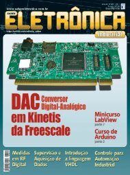
Figure 2 shows <strong>the</strong> oscilloscope trace of <strong>the</strong> 12-cycle, 40-kHz burst. Notice <strong>the</strong> 19.2-V peak to<br />
peak voltage swing. The ringing sine wave seen on top of <strong>the</strong> square waves is due to resonance<br />
in <strong>the</strong> transducer.<br />
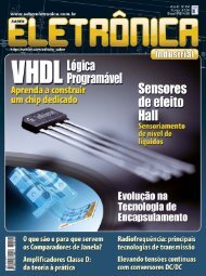
Figure 3 shows <strong>the</strong> oscilloscope traces for one complete measurement cycle. Trace 1 shows <strong>the</strong><br />
12-cycle, 40-kHz burst at <strong>the</strong> output of <strong>the</strong> transmitter transducer. Trace 2 shows <strong>the</strong> amplified<br />
receiver transducer output at pin 1 of <strong>the</strong> operational amplifier. The first burst-signal on <strong>the</strong> trace<br />
represents <strong>the</strong> signal directly received from <strong>the</strong> transmitter and is ignored by <strong>the</strong> <strong>MSP430</strong>. The<br />
next burst on <strong>the</strong> trace represents <strong>the</strong> echo reflected by <strong>the</strong> subject and is <strong>the</strong> signal used by <strong>the</strong><br />
<strong>MSP430</strong> for measurement. Trace 3 shows <strong>the</strong> width of <strong>the</strong> time interval measured by <strong>the</strong><br />
<strong>MSP430</strong>. This width represents <strong>the</strong> time it takes for <strong>the</strong> burst to travel <strong>the</strong> distance from <strong>the</strong><br />
measuring system to <strong>the</strong> subject and back, and it depends on <strong>the</strong> distance measured.<br />
<strong>Ultrasonic</strong> <strong>Distance</strong> <strong>Measurement</strong> With <strong>the</strong> <strong>MSP430</strong><br />
3
SLAA136A<br />
S1<br />
C1<br />
0.1µF<br />
1<br />
9–V<br />
Battery<br />
J1<br />
JTAG<br />
TPS<br />
77001<br />
1 5<br />
2<br />
3<br />
U2 4<br />
R2<br />
100K<br />
R12<br />
100K<br />
V CC<br />
Vcc<br />
RESET<br />
X1 XIN<br />
40KHz<br />
XOUT<br />
R1<br />
200K<br />
C3<br />
0.1µF<br />
TDO/TDI<br />
TDI<br />
TMS<br />
TCK<br />
V CC<br />
V SS<br />
4 <strong>Ultrasonic</strong> <strong>Distance</strong> <strong>Measurement</strong> With <strong>the</strong> <strong>MSP430</strong><br />
58<br />
8<br />
9<br />
R3<br />
100K<br />
R4<br />
100K<br />
f<br />
g<br />
a<br />
LCD1<br />
b<br />
e<br />
c e<br />
c 18<br />
d<br />
d<br />
COM<br />
g f e d c b a g f e d c b a<br />
17 16 3 4 5 14 15 13 12 7 8 9 10 11<br />
26 25 24 23 22 21 20 18 17 16 15 14 13 12<br />
36<br />
COM0<br />
54<br />
55<br />
56<br />
57<br />
U1<br />
<strong>MSP430</strong>F413<br />
6263 71011 46 48<br />
P1.6 P1.5<br />
CA0 ACLK<br />
f<br />
g<br />
a<br />
b<br />
1<br />
64<br />
40<br />
53<br />
C5<br />
22pF<br />
1<br />
COM<br />
R03<br />
P1.0<br />
R7<br />
5<br />
100K 1<br />
4<br />
U3<br />
TLV2771<br />
3<br />
2<br />
R6<br />
100K<br />
V CC<br />
C9<br />
0.1µF<br />
LED1<br />
R11<br />
560 Ω<br />
C8<br />
0.1 µF<br />
3.6V<br />
+ C2<br />
4.7µF<br />
VCC R8<br />
10K<br />
R9<br />
10K<br />
R10<br />
10K<br />
9 10<br />
Q1<br />
MMBT3904<br />
1<br />
7<br />
8<br />
5 4<br />
6<br />
C7<br />
3 2 0.2µF<br />
TX1<br />
U4 CD4049 40KHz<br />
11 12 US Transducer<br />
C6<br />
14 15<br />
0.2µF<br />
Figure 1. Circuit Schematic<br />
V CC<br />
R5<br />
1.8K<br />
C4<br />
0.1µF<br />
RX1<br />
40KHz<br />
US Transducer
Figure 2. Oscilloscope Trace of Transmitter’s 40-kHz Burst<br />
Figure 3. Oscilloscope Trace for One <strong>Measurement</strong> Cycle<br />
<strong>Ultrasonic</strong> <strong>Distance</strong> <strong>Measurement</strong> With <strong>the</strong> <strong>MSP430</strong><br />
SLAA136A<br />
5
SLAA136A<br />
3 Software <strong>Ultrasonic</strong>.s43<br />
3.1 Init_Device<br />
This subroutine initializes and configures <strong>the</strong> peripherals used. The Watchdog Timer is disabled<br />
first. A software delay is provided to allow <strong>the</strong> low-frequency oscillator to stabilize. The FLL+<br />
multiplier is set to 64 to produce an MCLK frequency of 2.56 MHz. P1.0 is configured as an<br />
output for <strong>the</strong> LED. The unused port pins are configured as outputs and port pin P1.5 is<br />
configured to output <strong>the</strong> 40-kHz buffered ACLK frequency. The Basic Timer1 is enabled and<br />
configured to provide a 150-Hz LCD frequency and to interrupt <strong>the</strong> CPU every 205 milliseconds<br />
to initiate a measurement cycle. The Comparator_A is configured <strong>with</strong> 0.5V CC internal reference<br />
and <strong>the</strong> CAPD bits are set to disable <strong>the</strong> input buffers for <strong>the</strong> comparator-input pins. The LCD<br />
module is turned on and configured for static-mode operation to drive <strong>the</strong> two-digit static LCD in<br />
<strong>the</strong> application. The LCD memory locations are cleared so that <strong>the</strong> initial LCD display is 00. The<br />
Basic Timer1 interrupt and <strong>the</strong> global interrupt enable are <strong>the</strong>n enabled to allow <strong>the</strong> Basic<br />
Timer1 to periodically interrupt <strong>the</strong> CPU.<br />
3.2 Mainloop<br />
Mainloop updates <strong>the</strong> LCD <strong>with</strong> <strong>the</strong> value stored in <strong>the</strong> DIGITS buffer and <strong>the</strong>n puts <strong>the</strong> <strong>MSP430</strong><br />
to LPM3 sleep mode. The <strong>MSP430</strong> remains in sleep mode until a Basic Timer1 interrupt occurs<br />
and BT_ISR returns it to active mode. Now a measurement cycle is initiated. Timer_A is<br />
configured to 16-bit up mode and ACLK is selected as <strong>the</strong> clock source for Timer_A. CCR1 is<br />
set to <strong>the</strong> compare mode <strong>with</strong> a value of 12 so as to output a burst of 12 cycles of 40 kHz on<br />
P1.5. A 36-ACLK cycles delay follows to allow <strong>the</strong> output transducer to settle. This is realized by<br />
setting CCR1 to <strong>the</strong> compare mode <strong>with</strong> a value of 36. The <strong>MSP430</strong> stays in LPM0 during <strong>the</strong>se<br />
CCR1-compare wait states.<br />
Now <strong>the</strong> system is set to receive <strong>the</strong> echo via <strong>the</strong> receiver transducer. The Comparator_A is<br />
configured to wait for <strong>the</strong> echo and it provides a capture interrupt at <strong>the</strong> instant <strong>the</strong> echo arrives.<br />
The Timer_A count is captured in capture-compare register CCR1. This value is <strong>the</strong> measure of<br />
<strong>the</strong> time it took <strong>the</strong> ultrasonic burst to travel <strong>the</strong> distance from <strong>the</strong> transmitter transducer to <strong>the</strong><br />
subject and back to <strong>the</strong> receiver transducer. The count value is adjusted by adding 48 to<br />
compensate for <strong>the</strong> time lost in <strong>the</strong> 12-cycle burst and <strong>the</strong> 36-cycle transducer settling time<br />
delay. The adjusted value in CCR1 represents <strong>the</strong> exact time interval from <strong>the</strong> instant of <strong>the</strong> start<br />
of <strong>the</strong> burst to <strong>the</strong> instant of <strong>the</strong> start of <strong>the</strong> echo at <strong>the</strong> system. Next, <strong>the</strong> math subroutine is<br />
called to compute <strong>the</strong> actual distance in inches and return <strong>the</strong> result. If <strong>the</strong> system is out of<br />
range, <strong>the</strong> echo signal is not received and <strong>the</strong> Comparator_A does not provide a capture<br />
interrupt. The <strong>MSP430</strong> stays in LPM0 until <strong>the</strong> next Basic Timer1 interrupt wakes it up. The<br />
CAIFG bit in <strong>the</strong> CCTL1 control register is <strong>the</strong>n tested to make sure that <strong>the</strong> echo was never<br />
received. To indicate this condition, a value of 0xBE is stored in DIGITS to display an E on <strong>the</strong><br />
LCD. The program finally loops back to Mainloop to update <strong>the</strong> LCD and go back to LPM3 sleep<br />
mode. The next Basic Timer1 interrupt returns <strong>the</strong> <strong>MSP430</strong> to active mode to repeat <strong>the</strong><br />
program execution sequence.<br />
6 <strong>Ultrasonic</strong> <strong>Distance</strong> <strong>Measurement</strong> With <strong>the</strong> <strong>MSP430</strong>
3.3 Math_calc<br />
<strong>Ultrasonic</strong> <strong>Distance</strong> <strong>Measurement</strong> With <strong>the</strong> <strong>MSP430</strong><br />
SLAA136A<br />
The Math_calc subroutine takes care of <strong>the</strong> ma<strong>the</strong>matical calculations required by this<br />
application. The adjusted 16-bit value from CCR1 is stored in <strong>the</strong> variable Result. This value is<br />
<strong>the</strong> representation of <strong>the</strong> time it takes <strong>the</strong> ultrasonic burst to travel <strong>the</strong> distance from <strong>the</strong> system<br />
to <strong>the</strong> subject and back to <strong>the</strong> system. Since Timer_A counts in 25-µs steps, <strong>the</strong> equivalent<br />
value in time will be Result X 25 µS. Assuming <strong>the</strong> speed of sound as 1100 ft/s at room<br />
temperature, <strong>the</strong> Result from <strong>the</strong> Timer_A count works out to be six counts per inch of distance.<br />
Therefore, dividing <strong>the</strong> Result by six produces <strong>the</strong> required value of <strong>the</strong> distance in inches.<br />
To achieve <strong>the</strong> required precision <strong>with</strong> <strong>the</strong> available integer math of <strong>the</strong> <strong>MSP430</strong>, <strong>the</strong> 16-bit<br />
Result is first multiplied by 100 before dividing it by 6. This 16X16-bit multiplication is done by<br />
<strong>the</strong> subroutine Mul100. The 32-bit result is stored in <strong>the</strong> variables htX100_msw and htX100_lsw.<br />
This 32-bit result is <strong>the</strong>n divided by 6 and <strong>the</strong> result is stored in <strong>the</strong> variable DIGITS. The value<br />
in DIGITS is in hexadecimal format. The hex2bcd subroutine converts this hexadecimal value to<br />
binary coded decimal (BCD) value, and <strong>the</strong> last two digits of <strong>the</strong> BCD number are discarded to<br />
compensate for <strong>the</strong> multiplication by 100 done earlier. The resulting two-digit value is returned to<br />
<strong>the</strong> variable DIGITS.<br />
3.4 BT_ISR<br />
The Basic Timer1 interrupt subroutine BT_ISR manipulates <strong>the</strong> bits in <strong>the</strong> status register SR<br />
residing in <strong>the</strong> stack such that <strong>the</strong> <strong>MSP430</strong> returns to active mode on return from this ISR. This<br />
allows <strong>the</strong> <strong>MSP430</strong> to continue to execute <strong>the</strong> code following <strong>the</strong> LPM3 instruction in Mainloop.<br />
3.5 Display<br />
This subroutine updates <strong>the</strong> two-digit static LCD <strong>with</strong> <strong>the</strong> value in <strong>the</strong> variable DIGITS. The<br />
segment data for <strong>the</strong> static display is stored in look-up table LCD_Tab. The LCD memory is<br />
loaded <strong>with</strong> <strong>the</strong> required segment data by correlating <strong>the</strong> numbers in DIGITS and indexing to <strong>the</strong><br />
required location in <strong>the</strong> LCD_Tab look-up table.<br />
3.6 Delay<br />
This subroutine adds a 16-bit software delay. No registers are affected as <strong>the</strong> variable to be<br />
counted down by software is assigned to <strong>the</strong> top of stack (TOS). After <strong>the</strong> delay is timed out, <strong>the</strong><br />
stack pointer (SP) is incremented back to <strong>the</strong> original value before returning from this<br />
subroutine.<br />
4 Conclusion<br />
The integrated analog Comparator_A, <strong>the</strong> 16-bit Timer_A <strong>with</strong> hardware capture/compare<br />
registers, <strong>the</strong> Basic Timer1, and <strong>the</strong> LCD driver peripherals simplify this ultrasonic distance<br />
measurement application design and provides a system-in-a-chip solution. The average current<br />
consumed by <strong>the</strong> application is 1.3 mA during a 15-inch distance measurement. This includes<br />
<strong>the</strong> quiescent current of LDO U2, operational amplifier U3, and CMOS hex inverter U4. The<br />
operational amplifier alone has a quiescent current of 1 mA and <strong>the</strong> remainder of <strong>the</strong> circuit<br />
current consumption is 300 µA. The LED draws 5 mA while it is on. The <strong>MSP430</strong> draws an<br />
average current of 2.1 µA <strong>with</strong> <strong>the</strong> LCD continuously active. This is made possible by taking<br />
advantage of <strong>the</strong> ultralow-current features of <strong>the</strong> <strong>MSP430</strong>. The <strong>MSP430</strong> sleeps in LPM3 most of<br />
<strong>the</strong> time and <strong>the</strong> CPU resources used by this application are only 5.6%.<br />
7
SLAA136A<br />
Since <strong>the</strong> speed of sound is temperature dependent, <strong>the</strong> measured reading will be less accurate<br />
at temperatures o<strong>the</strong>r than room temperature. A simple <strong>the</strong>rmistor-based temperature<br />
measurement and distance compensation could be employed in this application to allow <strong>the</strong><br />
system to measure accurately over a wide range of temperatures. The measured distance and<br />
temperature data could also be stored in <strong>the</strong> flash memory if required. Adding additional receiver<br />
gain stages and using a multiplexed LCD to read out as many digits as required could increase<br />
<strong>the</strong> range.<br />
5 References<br />
1. <strong>MSP430</strong>x41x Mixed Signal Microcontroller data sheet SLAS340<br />
2. <strong>MSP430</strong>x4xx Family User’s Guide, SLAU056<br />
3. <strong>MSP430</strong> Family Mixed-Signal Microcontrollers, application report SLAA024<br />
4. TPS770xx Ultra Low-Power LDO Linear Regulators, data sheet SLVS210<br />
5. TLV277x Family of High-Slew-Rate Operational Amplifiers, data sheet SLOS209<br />
6. CD4049UB, CMOS Hex Inverting Buffer/Converter, data sheet SCHS046A<br />
8 <strong>Ultrasonic</strong> <strong>Distance</strong> <strong>Measurement</strong> With <strong>the</strong> <strong>MSP430</strong>
Appendix A Programming Code<br />
; THIS PROGRAM IS PROVIDED ”AS IS”. TI MAKES NO WARRANTIES OR<br />
; REPRESENTATIONS, EITHER EXPRESS, IMPLIED OR STATUTORY,<br />
; INCLUDING ANY IMPLIED WARRANTIES OF MERCHANTABILITY, FITNESS<br />
; FOR A PARTICULAR PURPOSE, LACK OF VIRUSES, ACCURACY OR<br />
; COMPLETENESS OF RESPONSES, RESULTS AND LACK OF NEGLIGENCE.<br />
; TI DISCLAIMS ANY WARRANTY OF TITLE, QUIET ENJOYMENT, QUIET<br />
; POSSESSION, AND NON–INFRINGEMENT OF ANY THIRD PARTY<br />
; INTELLECTUAL PROPERTY RIGHTS WITH REGARD TO THE PROGRAM OR<br />
; YOUR USE OF THE PROGRAM.<br />
;<br />
; IN NO EVENT SHALL TI BE LIABLE FOR ANY SPECIAL, INCIDENTAL,<br />
; CONSEQUENTIAL OR INDIRECT DAMAGES, HOWEVER CAUSED, ON ANY<br />
; THEORY OF LIABILITY AND WHETHER OR NOT TI HAS BEEN ADVISED<br />
; OF THE POSSIBILITY OF SUCH DAMAGES, ARISING IN ANY WAY OUT<br />
; OF THIS AGREEMENT, THE PROGRAM, OR YOUR USE OF THE PROGRAM.<br />
; EXCLUDED DAMAGES INCLUDE, BUT ARE NOT LIMITED TO, COST OF<br />
; REMOVAL OR REINSTALLATION, COMPUTER TIME, LABOR COSTS, LOSS<br />
; OF GOODWILL, LOSS OF PROFITS, LOSS OF SAVINGS, OR LOSS OF<br />
; USE OR INTERRUPTION OF BUSINESS. IN NO EVENT WILL TI’S<br />
; AGGREGATE LIABILITY UNDER THIS AGREEMENT OR ARISING OUT OF<br />
; YOUR USE OF THE PROGRAM EXCEED FIVE HUNDRED DOLLARS<br />
; (U.S.$500).<br />
;<br />
; Unless o<strong>the</strong>rwise stated, <strong>the</strong> Program written and copyrighted<br />
; by Texas Instruments is distributed as ”freeware”. You may,<br />
; only under TI’s copyright in <strong>the</strong> Program, use and modify <strong>the</strong><br />
; Program <strong>with</strong>out any charge or restriction. You may<br />
; distribute to third parties, provided that you transfer a<br />
; copy of this license to <strong>the</strong> third party and <strong>the</strong> third party<br />
; agrees to <strong>the</strong>se terms by its first use of <strong>the</strong> Program. You<br />
; must reproduce <strong>the</strong> copyright notice and any o<strong>the</strong>r legend of<br />
; ownership on each copy or partial copy, of <strong>the</strong> Program.<br />
;<br />
; You acknowledge and agree that <strong>the</strong> Program contains<br />
; copyrighted material, trade secrets and o<strong>the</strong>r TI proprietary<br />
; information and is protected by copyright laws,<br />
; international copyright treaties, and trade secret laws, as<br />
; well as o<strong>the</strong>r intellectual property laws. To protect TI’s<br />
<strong>Ultrasonic</strong> <strong>Distance</strong> <strong>Measurement</strong> With <strong>the</strong> <strong>MSP430</strong><br />
SLAA136A<br />
9
SLAA136A<br />
; rights in <strong>the</strong> Program, you agree not to decompile, reverse<br />
; engineer, disassemble or o<strong>the</strong>rwise translate any object code<br />
; versions of <strong>the</strong> Program to a human–readable form. You agree<br />
; that in no event will you alter, remove or destroy any<br />
; copyright notice included in <strong>the</strong> Program. TI reserves all<br />
; rights not specifically granted under this license. Except<br />
; as specifically provided herein, nothing in this agreement<br />
; shall be construed as conferring by implication, estoppel,<br />
; or o<strong>the</strong>rwise, upon you, any license or o<strong>the</strong>r right under any<br />
; TI patents, copyrights or trade secrets.<br />
;<br />
; You may not use <strong>the</strong> Program in non–TI devices.<br />
;<br />
;******************************************************************************<br />
NAME ULTRASONIC_DISTANCE_MEASUREMENT<br />
;AUTHOR Murugavel Raju<br />
; <strong>MSP430</strong> Applications<br />
; Texas Instruments Inc.<br />
; Feb 2001<br />
#include ”msp430x41x.h” ; Standard Equations<br />
;<br />
;******************************************************************************<br />
; <strong>MSP430</strong>F413 <strong>Ultrasonic</strong> <strong>Distance</strong> <strong>Measurement</strong> Demonstration Program<br />
;<br />
;******************************************************************************<br />
;Register definitions<br />
;******************************************************************************<br />
#define DIGITS R11<br />
#define Result R10<br />
#define IRBT R9<br />
#define IROP1 R4<br />
#define IROP2L R5<br />
#define IROP2M R6<br />
#define IRACL R7<br />
#define IRACM R8<br />
;******************************************************************************<br />
;Variables definition<br />
;******************************************************************************<br />
RSEG UDATA0<br />
htX100_msw: DS 2 ; word variable stored in RAM 200h & 201h<br />
10 <strong>Ultrasonic</strong> <strong>Distance</strong> <strong>Measurement</strong> With <strong>the</strong> <strong>MSP430</strong>
htX100_lsw: DS 2 ; 202h & 203h<br />
;******************************************************************************<br />
RSEG CSTACK ; Directive to begin stack segment<br />
DS 0<br />
RSEG CODE ; Directive to begin code segment<br />
RESET mov.w #SFE(CSTACK),SP ; Define stack pointer<br />
call #Init_Device ; Initialize device<br />
mov.w #0,DIGITS ; Initialize DIGITS to ’0’<br />
Mainloop<br />
bic.b #CAON,&CACTL1 ; Comparator_A OFF<br />
call #Display ; Display Data on LCD<br />
bis.w #LPM3,SR ; Wait in LPM3<br />
;***************Start <strong>Ultrasonic</strong> Bursts and take measurements *****************<br />
clr.w &CCTL1 ; Disable CCTL1<br />
clr.w &TACTL ; Disable timer_A<br />
bis.b #BIT0,&P1OUT ; LED ON<br />
SetupTimerA mov.w #TASSEL0+TACLR+MC1,&TACTL<br />
; TACLK = ACLK, 16 bit up mode<br />
bis.b #BIT5,&P1SEL ; ACLK o/p on P1.5<br />
mov.w #12,&CCR1 ; 12 cycle 40KHz burst<br />
mov.w #CCIE,&CCTL1 ; Compare mode,interrupt<br />
bis.w #LPM0,SR ; Wait for CCR1 interrupt<br />
bic.b #BIT5,&P1SEL ; ACLK o/p on P1.5 OFF<br />
TimerCLR bis.w #TACLR,&TACTL<br />
mov.w #36,&CCR1 ; Delay for transducer to settle<br />
mov.w #CCIE,&CCTL1 ; Compare mode,interrupt<br />
bis.w #LPM0,SR ; Wait for CCR1 interrupt<br />
<strong>Ultrasonic</strong> <strong>Distance</strong> <strong>Measurement</strong> With <strong>the</strong> <strong>MSP430</strong><br />
SLAA136A<br />
bis.b #CAON,&CACTL1 ; Comparator_A ON<br />
bic.b #CAIFG,&CACTL1 ; Enable Comparator_A interrupt flag<br />
mov.w #CM0+CCIS0+SCS+CAP+CCIE,&CCTL1<br />
; Pos edge, CCIB,Cap,interrupt<br />
push &TAR ; TOS = TAR at Start of measurement<br />
bis.w #LPM0,SR ; Wait for CCR1 interrupt (Echo)<br />
clr.w &CCTL1 ; Disable CCTL1<br />
bic.b #BIT0,&P1OUT ; LED OFF<br />
bit.b #CAIFG,&CACTL1 ; Check for Echo not received<br />
11
SLAA136A<br />
jz Next ; ’out of range’ condition<br />
mov.w &CCR1,Result ; Result = TAR (CCR1) at EOC<br />
sub.w @SP+,Result ; Result = time taken<br />
add.w #48,Result ; compensate 12Clks for <strong>the</strong> burst<br />
; transmission time + 36Clks delay<br />
;****************** <strong>Measurement</strong> Done ******************************************<br />
call #Math_calc ; Call Math subroutine<br />
swpb DIGITS ; Shift left by two digits for /100<br />
jmp Mainloop ; next measurement cycle<br />
Next mov.w #0beh,DIGITS ; No echo received display ’E’ error<br />
jmp Mainloop<br />
;******************************************************************************<br />
Init_Device ; Initialize <strong>MSP430</strong>x41x<br />
;******************************************************************************<br />
mov.w #WDTPW+WDTHOLD,&WDTCTL ; Stop WDT<br />
bis.b #030h,&FLL_CTL0 ; Turn on internal load capacitors<br />
; for <strong>the</strong> XTAL to start oscillation<br />
call #Delay ; Delay for oscillator to stabilize<br />
mov.b #03fh,&SCFQCTL ; MCLK = 40KhzX64 = 2.56Mhz<br />
call #Delay ; Delay for FLL to stabilize<br />
SetupP1 mov.b #000h,&P1OUT ; Clear P1 output register<br />
bis.b #0bfh,&P1DIR ; Unused pins as o/p’s<br />
bis.b #040h,&P1SEL ; Comp_A + i/p function<br />
SetupP2 mov.b #000h,&P2OUT ; Clear P2 output register<br />
bis.b #0ffh,&P2DIR ; Unused pins as o/p’s<br />
SetupP6 mov.b #000h,&P6OUT ; Clear P6 output register<br />
bis.b #0ffh,&P6DIR ; Unused pins as o/p’s<br />
SetupBT mov.b #BTFRFQ0+BTFRFQ1+BTIP2+BTDIV,&BTCTL<br />
; Enable BT <strong>with</strong> 150Hz LCD freq.<br />
; and 205 millisecond interrupt<br />
SetupCA mov.b #CAPD6,&CAPD ; o/p buffer disable for comp i/p<br />
mov.b #P2CA0,&CACTL2 ; P1.6 to Comp + input<br />
mov.b #CARSEL+CAREF1+CAON,&CACTL1<br />
12 <strong>Ultrasonic</strong> <strong>Distance</strong> <strong>Measurement</strong> With <strong>the</strong> <strong>MSP430</strong>
; Comp_A ON, 0.5Vcc int. reference<br />
SetupLCD bis.b #LCDON+LCDSON+LCDSG0_7,LCDCTL<br />
; LCD module ON and in static mode<br />
ClearLCD mov #15,R15 ; 15 LCD mem locations to clear<br />
mov.b #LCDMEM,R14<br />
Clear1 mov.b #0,0(R14) ; Write zeros in LCD RAM locations<br />
inc.b R14<br />
dec R15 ; All LCD mem clear?<br />
jnz Clear1 ; More LCD mem to clear go<br />
bis.b #BTIE,&IE2 ; Enable Basic Timer interrupt<br />
eint ; Enable interrupts<br />
ret<br />
;******************************************************************************<br />
BT_ISR ; Basic Timer ISR, CPU returns<br />
; to active mode on RETI<br />
;******************************************************************************<br />
bic #LPM3,0(SP) ; Clear LPM3 bits on TOS<br />
reti ; on return from interrupt<br />
;******************************************************************************<br />
TAX_ISR; Common ISR for CCR1–4 and overflow<br />
;******************************************************************************<br />
add.w &TAIV,PC ; Add TA interrupt offset to PC<br />
reti ; CCR0 – no source<br />
jmp CCR1_ISR ; CCR1<br />
reti ; CCR2<br />
reti ; CCR3<br />
reti ; CCR4<br />
TA_over reti ; Timer_A overflow<br />
CCR1_ISR bic.w #CCIFG,&CCTL1<br />
bic.w #LPM0,0(SP) ; Exit LPM0 on reti<br />
reti ;<br />
;******************************************************************************<br />
Display ;Subroutine to Display values DIGIT1 & DIGIT2<br />
;CPU Registers used R15, R14, R13 and R12, not saved<br />
;******************************************************************************<br />
mov.w #LCDM1,R15 ; R15 points to first LCD location<br />
<strong>Ultrasonic</strong> <strong>Distance</strong> <strong>Measurement</strong> With <strong>the</strong> <strong>MSP430</strong><br />
SLAA136A<br />
13
SLAA136A<br />
mov.b DIGITS,R14 ; LSD value moved to R14<br />
OutLCD mov.b R14,R13 ; Copy value in R14 to R13<br />
rra.b R13 ; Right Shift<br />
rra.b R13 ; four times to<br />
rra.b R13 ; swap<br />
rra.b R13 ; nibbles<br />
and.b #0Fh,R14 ; low nibble now in R14<br />
and.b #0Fh,R13 ; high nibble now in R13<br />
mov.b LCD_Tab(R14),R12 ; Low nibble to LCD digit 1<br />
mov.b R12,0(R15) ; Low nibble segments a & b to LCD<br />
rra.w R12<br />
inc.b R15<br />
mov.b R12,0(R15) ; Low nibble segments c & d to LCD<br />
rra.w R12<br />
inc.b R15<br />
mov.b R12,0(R15) ; Low nibble segments e & f to LCD<br />
rra.w R12<br />
inc.b R15<br />
mov.b R12,0(R15) ; Low nibble segments g & h to LCD<br />
rra.w R12<br />
inc.b R15<br />
mov.b LCD_Tab(R13),R12 ; High nibble to LCD digit 2<br />
mov.b R12,0(R15) ; High nibble segments a & b to LCD<br />
rra.w R12<br />
inc.b R15<br />
mov.b R12,0(R15) ; High nibble segments c & d to LCD<br />
rra.w R12<br />
inc.b R15<br />
mov.b R12,0(R15) ; High nibble segments e & f to LCD<br />
rra.w R12<br />
inc.b R15<br />
mov.b R12,0(R15) ; High nibble segments g & h to LCD<br />
rra.w R12<br />
ret<br />
;******************************************************************************<br />
; LCD Type Definition<br />
;******************************************************************************<br />
;Segments definition<br />
a equ 001h<br />
b equ 010h<br />
14 <strong>Ultrasonic</strong> <strong>Distance</strong> <strong>Measurement</strong> With <strong>the</strong> <strong>MSP430</strong>
c equ 002h<br />
d equ 020h<br />
e equ 004h<br />
f equ 040h<br />
g equ 008h<br />
h equ 080h<br />
Blank equ 000h<br />
LCD_Tab db a+b+c+d+e+f ; Displays ”0”<br />
db b+c ; Displays ”1”<br />
db a+b+d+e+g ; Displays ”2”<br />
db a+b+c+d+g ; Displays ”3”<br />
db b+c+f+g ; Displays ”4”<br />
db a+c+d+f+g ; Displays ”5”<br />
db a+c+d+e+f+g ; Displays ”6”<br />
db a+b+c ; Displays ”7”<br />
db a+b+c+d+e+f+g ; Displays ”8”<br />
db a+b+c+d+f+g ; Displays ”9”<br />
db a+b+c+e+f+g ; Displays ”A”<br />
db Blank ; Displays Blank<br />
db a+d+e+f ; Displays ”C”<br />
db b+c+d+e+g ; Displays ”D” d<br />
db a+d+e+f+g ; Displays ”E”<br />
db a+e+f+g ; Displays ”F”<br />
;******************************************************************************<br />
Delay; Software delay<br />
;******************************************************************************<br />
push #0FFFFh ; Delay to TOS<br />
DL1 dec.w 0(SP) ; Decrement TOS<br />
jnz DL1 ; Delay over?<br />
incd SP ; Clean TOS<br />
ret ; Return from subroutine<br />
;******************************************************************************<br />
Math_calc; calculation subroutine<br />
;******************************************************************************<br />
mov.w #0h, DIGITS ; Initialize DIGIT to 0<br />
cmp.w #0h, Result ; Check if Result count=0<br />
jeq calc_over ; Exit if 0<br />
call #Mul100 ; Multiply Result count by 100<br />
<strong>Ultrasonic</strong> <strong>Distance</strong> <strong>Measurement</strong> With <strong>the</strong> <strong>MSP430</strong><br />
SLAA136A<br />
15
SLAA136A<br />
call #Divide ; Divide <strong>the</strong> result <strong>with</strong> #06d<br />
call #Hex2bcd ; Convert 16bit binary to BCD number<br />
; Result xx.xx<br />
calc_over ret ; Return from subroutine<br />
;******************************************************************************<br />
Mul100 ;subroutine for multiplying Result <strong>with</strong> 100d<br />
;inputs Result 16bit and constant 64h (100d) 16bit<br />
;output 32bit htX100_msw & htX100_lsw<br />
;******************************************************************************<br />
mov.w #100,IROP1 ; Load IROP1 <strong>with</strong> 100 (multiplier)<br />
mpyu clr.w htX100_lsw ; Clear buffer for least<br />
; Significant word<br />
clr.w htX100_msw ; Clear buffer for most<br />
; Significant word<br />
macu clr.w IROP2M ; Clear multiplier high word<br />
L$002 bit.w #1,IROP1 ; Test actual bit<br />
jz L$01 ; If 0: do nothing<br />
add.w Result,htX100_lsw ; If 1: Add multiplier to Result<br />
addc.w IROP2M,htX100_msw ;<br />
L$01 rla.w Result ; Multiplier X 2<br />
rlc.w IROP2M ;<br />
rrc.w IROP1 ; Next bit to test<br />
jnz L$002 ; If bit in carry : finished<br />
ret<br />
;******************************************************************************<br />
Divide ;Subroutine for 32/16 bits division<br />
;inputs 32bit htX100_msw & htX100_lsw and #06 16bit, output DIGIT<br />
16bit<br />
;******************************************************************************<br />
clr.w DIGITS ; Clear buffer to hold new Result<br />
mov.w #17,IRBT ; Initialize loop counter<br />
div1 cmp.w #06,htX100_msw ; Compare divisor <strong>with</strong> dividend high<br />
word<br />
jlo div2 ; If less : jump to div2<br />
sub.w #06,htX100_msw ; Subtract 6 from high word<br />
div2 rlc.w DIGITS ; Rotate result left through carry 1<br />
bit<br />
jc div4 ; If carry set: finished<br />
dec.w IRBT ; Decrement bit counter<br />
16 <strong>Ultrasonic</strong> <strong>Distance</strong> <strong>Measurement</strong> With <strong>the</strong> <strong>MSP430</strong>
<strong>Ultrasonic</strong> <strong>Distance</strong> <strong>Measurement</strong> With <strong>the</strong> <strong>MSP430</strong><br />
SLAA136A<br />
jz div3 ; If counter = 0 : finished<br />
rla.w htX100_lsw ; Dividend X 2<br />
rlc.w htX100_msw ;<br />
jnc div1 ; If carry not set jump to step div1<br />
sub.w #06,htX100_msw ; Subtract 6 from high word<br />
setc ; Set carry<br />
jmp div2 ; Jump to repeat<br />
div3 clrc ; Clear carry<br />
div4 ret ; Return from subroutine<br />
;******************************************************************************<br />
Hex2bcd ;Subroutine for converting 16bit hexadecimal value to BCD value<br />
;input in DIGITS 16bit hexadecimal, output in DIGITS 16bit BCD<br />
;******************************************************************************<br />
mov #16,r9 ; R9 no of bits<br />
clr r8 ; Clear R8<br />
clr r7 ; Clear R7<br />
L$1 rla DIGITS ; Rotate left arithmetic DIGITS<br />
dadd r7,r7 ; Add source and carry decimally<br />
dadd r8,r8 ; to destination<br />
dec r9 ; Decrement bit counter<br />
jnz L$1 ; Is 16 bits over ?<br />
mov r7,DIGITS ; Result in DIGITS<br />
ret ; Return from subroutine<br />
;******************************************************************************<br />
COMMON INTVEC ; <strong>MSP430</strong>x41x Interrupt vectors<br />
;******************************************************************************<br />
ORG BASICTIMER_VECTOR<br />
BT_VEC DW BT_ISR ; Basic Timer Vector<br />
ORG TIMERA1_VECTOR ; Timer_AX Vector<br />
TIMA_VEC DW TAX_ISR ;<br />
ORG RESET_VECTOR<br />
RESET_VEC DW RESET ; POR, ext. Reset, Watchdog<br />
;******************************************************************************<br />
END<br />
Title<br />
17
IMPORTANT NOTICE<br />
Texas Instruments Incorporated and its subsidiaries (TI) reserve <strong>the</strong> right to make corrections, modifications,<br />
enhancements, improvements, and o<strong>the</strong>r changes to its products and services at any time and to discontinue<br />
any product or service <strong>with</strong>out notice. Customers should obtain <strong>the</strong> latest relevant information before placing<br />
orders and should verify that such information is current and complete. All products are sold subject to TI’s terms<br />
and conditions of sale supplied at <strong>the</strong> time of order acknowledgment.<br />
TI warrants performance of its hardware products to <strong>the</strong> specifications applicable at <strong>the</strong> time of sale in<br />
accordance <strong>with</strong> TI’s standard warranty. Testing and o<strong>the</strong>r quality control techniques are used to <strong>the</strong> extent TI<br />
deems necessary to support this warranty. Except where mandated by government requirements, testing of all<br />
parameters of each product is not necessarily performed.<br />
TI assumes no liability for applications assistance or customer product design. Customers are responsible for<br />
<strong>the</strong>ir products and applications using TI components. To minimize <strong>the</strong> risks associated <strong>with</strong> customer products<br />
and applications, customers should provide adequate design and operating safeguards.<br />
TI does not warrant or represent that any license, ei<strong>the</strong>r express or implied, is granted under any TI patent right,<br />
copyright, mask work right, or o<strong>the</strong>r TI intellectual property right relating to any combination, machine, or process<br />
in which TI products or services are used. Information published by TI regarding third–party products or services<br />
does not constitute a license from TI to use such products or services or a warranty or endorsement <strong>the</strong>reof.<br />
Use of such information may require a license from a third party under <strong>the</strong> patents or o<strong>the</strong>r intellectual property<br />
of <strong>the</strong> third party, or a license from TI under <strong>the</strong> patents or o<strong>the</strong>r intellectual property of TI.<br />
Reproduction of information in TI data books or data sheets is permissible only if reproduction is <strong>with</strong>out<br />
alteration and is accompanied by all associated warranties, conditions, limitations, and notices. Reproduction<br />
of this information <strong>with</strong> alteration is an unfair and deceptive business practice. TI is not responsible or liable for<br />
such altered documentation.<br />
Resale of TI products or services <strong>with</strong> statements different from or beyond <strong>the</strong> parameters stated by TI for that<br />
product or service voids all express and any implied warranties for <strong>the</strong> associated TI product or service and<br />
is an unfair and deceptive business practice. TI is not responsible or liable for any such statements.<br />
Mailing Address:<br />
Texas Instruments<br />
Post Office Box 655303<br />
Dallas, Texas 75265<br />
Copyright © 2002, Texas Instruments Incorporated