Introducing the GV3 linear guidance and transmission system
Introducing the GV3 linear guidance and transmission system
Introducing the GV3 linear guidance and transmission system

You also want an ePaper? Increase the reach of your titles
YUMPU automatically turns print PDFs into web optimized ePapers that Google loves.
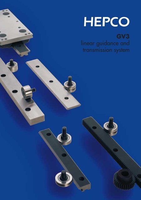
<strong>GV3</strong><br />
<strong>linear</strong> <strong>guidance</strong> <strong>and</strong><br />
<strong>transmission</strong> <strong>system</strong>
<strong>Introducing</strong> <strong>the</strong> <strong>GV3</strong><br />
<strong>linear</strong> <strong>guidance</strong> <strong>and</strong><br />
<strong>transmission</strong> <strong>system</strong><br />
The <strong>GV3</strong> <strong>linear</strong> <strong>guidance</strong> <strong>and</strong> <strong>transmission</strong> <strong>system</strong> has<br />
been designed to provide <strong>the</strong> customer with an unrivalled<br />
choice of sizes <strong>and</strong> options to cater for virtually every<br />
<strong>linear</strong> motion requirement.<br />
In devising <strong>GV3</strong>, Hepco have retained <strong>the</strong> best features<br />
of <strong>the</strong>ir highly successful Generation 2 <strong>and</strong> CM Slide<br />
Systems in a greatly exp<strong>and</strong>ed range. Many new<br />
components have been added including Single Edge<br />
Slides, Flat Tracks <strong>and</strong> drive options.<br />
Customers may now choose Slides from three grades<br />
of precision <strong>and</strong> combine <strong>the</strong>m with ei<strong>the</strong>r Twin Bearings,<br />
Double Row Bearings or low cost Slimline Bearings.<br />
This enables <strong>the</strong> ideal <strong>system</strong> to be specified for<br />
optimum performance within <strong>the</strong> budget available.<br />
The reliability of Hepco’s all steel slideway <strong>and</strong><br />
V bearing concept has been proved conclusively over<br />
nearly fifty years. Improvements are continually being<br />
made to this fundamentally sound design resulting in<br />
a truly evolutionary <strong>system</strong> for <strong>the</strong> 21st century.<br />
By choosing <strong>GV3</strong>, customers can be assured of a quality<br />
<strong>and</strong> performance which surpasses all expectations.<br />
<strong>GV3</strong> Benefits<br />
CAD CAD disk available<br />
SMOOTH: ● High accuracy <strong>and</strong> fine finish of components ➤➤➤ allows constant driving force without vibration.<br />
● Friction free motion ➤➤➤ allows smaller, lower cost motors to be selected.<br />
FAST: ● Optimised Bearing <strong>and</strong> Slide interface design ➤➤➤ enables very high speeds with low wear.<br />
● Low stick friction <strong>and</strong> low inertia of Bearing rotation ➤➤➤ allows fast acceleration for shortest stroke.<br />
ACCURATE: ● High degree of Slide parallelism <strong>and</strong> minimum Bearing clearance ➤➤➤ results in virtually zero play.<br />
● Important dimensions accurately controlled ➤➤➤ for reliable <strong>system</strong> height <strong>and</strong> positional accuracy.<br />
QUIET: ● Specially designed Bearing <strong>and</strong> Slide geometry ➤➤➤ results in one of <strong>the</strong> quietest slide <strong>system</strong>s available.<br />
DURABLE: ● All steel Slideway ➤➤➤ three times stiffer than composite aluminium slide <strong>system</strong>s.<br />
● Rugged construction ➤➤➤ suits high duty applications <strong>and</strong> harsh environments.<br />
● Lubrication devices available ➤➤➤ maximises life with no relubrication necessary in most instances.<br />
● Unique wiping action ➤➤➤ expels debris in environments where o<strong>the</strong>r <strong>system</strong>s fail.<br />
● Compliant bearing design ➤➤➤ for tolerance of misalignment.<br />
● Reliable performance confirmed by testing ➤➤➤ specify Hepco with confidence.<br />
SIMPLE: ● Easily understood proven technology ➤➤➤ little to go wrong <strong>and</strong> simple to maintain.<br />
VERSATILE: ● Huge range of sizes, types <strong>and</strong> ancillary components available ➤➤➤ provides solution to most design problems.<br />
● Long lengths available up to 4 m in most sizes ➤➤➤ saves on assembly time.<br />
● Available as assembled unit or in component form ➤➤➤ provides maximum flexibility of design.<br />
● Works in any plane <strong>and</strong> orientation ➤➤➤ unrestricted use in machine construction.<br />
● Operates without lubrication ➤➤➤ ideal for food machinery <strong>and</strong> clean applications.<br />
● Driven <strong>system</strong>s available ➤➤➤ complete solutions from a single source saves design <strong>and</strong> administration time.<br />
ECONOMIC: ● Choice of Slide precision <strong>and</strong> bearing design ➤➤➤ to match cost/performance requirements.<br />
● Designed for minimum installation time ➤➤➤ significantly reduces cost.
Contents<br />
Page<br />
System Composition 2-7<br />
Application Examples 8-16<br />
System Selector 17<br />
Data <strong>and</strong> Dimensions for Individual Components<br />
Carriages 18-23<br />
‘V’ Slides 24-29<br />
Slide Beams 30-31<br />
‘V’ Bearings 32-35<br />
Cap Seals, Cap Wipers <strong>and</strong> Lubricators 36-38<br />
Flange Clamps 39<br />
Flat Tracks 40<br />
Track Rollers 41-43<br />
Racks 44<br />
Pinions 45<br />
Belt Driven Carriages, Belts & Pulleys 46-47<br />
Rack Driven Carriages 48-49<br />
Gearboxes, AC Geared Motors & Flanges 50-51<br />
AC Speed Controller & Ancillary Components 52-53<br />
Data <strong>and</strong> Dimensions for Assembled Systems<br />
‘V’ Slide Systems 54-55<br />
Systems with Track Rollers, Racks & Pinions<br />
Technical Data<br />
56-57<br />
Load/Life Calculations <strong>and</strong> Examples 58-62<br />
Deflection of Self-Supporting Slides 63<br />
Drive Calculations for Rack Driven Carriages 64-65<br />
System Assembly <strong>and</strong> Adjustment 66-67<br />
Technical Specifications 68<br />
How To Use This Catalogue<br />
The <strong>GV3</strong> product range is large, so to help readers find <strong>the</strong>ir way around <strong>the</strong> catalogue, <strong>the</strong> following aids have been devised:<br />
St<strong>and</strong>ard Bearings<br />
All Hepco St<strong>and</strong>ard Bearings are compatible with all grades of Slide <strong>and</strong> although designed to be used with particular sizes<br />
of slide, may be "mixed <strong>and</strong> matched" in many instances. The following Bearing formats <strong>and</strong> fixing methods may be chosen<br />
to cater for most design requirements.<br />
The Twin Bearing type which is <strong>the</strong> default choice, comprises two individual deep groove ball bearings on a single<br />
stud. This construction offers some compliance allowing smoo<strong>the</strong>r running, easy adjustment <strong>and</strong> greater tolerance of misalignment.<br />
The Double Row Bearing type (DR) incorporates a one-piece bearing with two ball tracks. This offers higher load<br />
capacity, especially in <strong>the</strong> radial direction <strong>and</strong> is less susceptible to entrapment of debris.<br />
Both types of bearing have been designed specially for Slide <strong>system</strong> applications <strong>and</strong> <strong>the</strong>ir performance confirmed by rigorous<br />
testing. External dimensions are identical.<br />
The Nitrile Sealed option (NS) available for both bearing formats, provides a higher degree of sealing against ingress<br />
of water or debris than does <strong>the</strong> default metal shielded type. A small increase in friction may result.<br />
The Through Hole Fixing type is available in two stud lengths covering most thicknesses of carriage or mounting plate,<br />
<strong>the</strong> short stud version being compatible with <strong>the</strong> Hepco Carriage plates. Both versions are available in Concentric type (C)<br />
Through Fixing Type (SJ/LJ)<br />
B1<br />
C1<br />
C2<br />
* 3 L 2 O*1<br />
*<br />
F M M1<br />
Eccentrics (E & DE) Concentric (C)<br />
A<br />
N<br />
St<strong>and</strong>ard Bearings<br />
which are fixed, Eccentric type (E), adjustable <strong>and</strong> Double Eccentric type (DE)* 5 which have sufficient adjustment to<br />
enable a carriage to be disengaged from <strong>the</strong> Slide (see application drawing on page 8).<br />
All Through Hole Fixing types are available in a Controlled Height version (CH)* 7 which minimises variation between<br />
Bearings in respect of <strong>the</strong> important 'B1' dimension. This may be desirable in some high precision applications.<br />
The Blind Hole Fixing type (BH) allows mounting into a solid machine base where through mounting holes are not<br />
possible, or where <strong>the</strong> thickness of <strong>the</strong> mounting plate is too great (see application drawings on page 16). The Blind Hole<br />
Fixing type is also useful where adjustment from <strong>the</strong> front is preferred or where access to <strong>the</strong> opposite side of <strong>the</strong> mounting<br />
hole is restricted. They are available in Concentric type (C) which are fixed, or Eccentric type (E) * 6 which are<br />
adjustable.<br />
All Bearings are greased for life internally. Customers are strongly recommended to provide lubrication to <strong>the</strong> interface<br />
between Bearings <strong>and</strong> Slide by specifying Hepco Cap Seals which fit over <strong>the</strong> bearings, or by using Hepco Lubricators.<br />
Lubrication greatly increases load capacity <strong>and</strong> life.<br />
See Application Examples on pages 8-16<br />
Blind Hole Fixing Type (BHJ)<br />
Notes:<br />
1. It is recommended that holes to suit Bearing mounting studs should be reamed to tolerance F6 for a sliding fit.<br />
2. All eccentric Through Fixing type Bearing studs are supplied with sockets for adjustment as shown, with <strong>the</strong> exception of size 13.<br />
3. Nuts for <strong>the</strong> Through Fixing type Bearings are chemically blacked on <strong>the</strong> concentric version <strong>and</strong> bright zinc plated on <strong>the</strong> eccentrics for identification purposes.<br />
4. ‘R’ dimension is both <strong>the</strong> eccentric offset of <strong>the</strong> adjusting nut <strong>and</strong> <strong>the</strong> total adjustment available at <strong>the</strong> bearing centre line for 360<br />
32<br />
33<br />
0 J<br />
70°<br />
K<br />
B<br />
B/H<br />
Q<br />
B<br />
C<br />
P<br />
Socket Tool<br />
Y<br />
(for part no. &<br />
tightening torques<br />
T<br />
B<br />
see page 63)<br />
T2<br />
T1<br />
Short Stud Long Stud<br />
Adjusting Wrench<br />
(SJ)<br />
(LJ)<br />
(for part no. &<br />
‘X’ - 2 cap screws<br />
S<br />
S1<br />
tightening torques<br />
DIN 912 (supplied)<br />
U<br />
see page 67)<br />
U1<br />
Ordering Details<br />
Fixing type. Choose from:<br />
Controlled Height*<br />
rotation of <strong>the</strong> adjusting nut.<br />
SJ = Short Stud, LJ = Long Stud<br />
5. Double Eccentric Bearings require different mounting hole centres (please see page 20, dimension H1).<br />
& BHJ = Blind Hole Fixing<br />
6. The Blind Hole eccentric Bearings cannot be fitted with Cap Seals, however Lubricators may be specified instead.<br />
7. Controlled Height Bearings are selected within ±0.005 mm in respect of B1 dimension compared to <strong>the</strong> normal tolerance of ±0.025 mm. They are supplied<br />
Part Number (~ Bearing Diameter in mm)<br />
in sets of up to eight Bearings within <strong>the</strong> same tolerance b<strong>and</strong>. Larger quantities of Bearings within <strong>the</strong> same tolerance b<strong>and</strong> are available on request.<br />
C = Concentric (fixed), E = Eccentric (adjustable)<br />
8. The quoted static <strong>and</strong> dynamic load capacities are based on industry st<strong>and</strong>ard calculations. These do not accurately reflect <strong>system</strong> performance, <strong>and</strong> are only provided<br />
or DE = Double Eccentric (for disengagement purposes)<br />
for comparison with o<strong>the</strong>r <strong>system</strong>s. Please use <strong>the</strong> Max Working Load figures <strong>and</strong> <strong>the</strong> load/life calculations on pages 58-61 to determine <strong>system</strong> performance.<br />
9. The preferred Slide choices for each Bearing are listed. O<strong>the</strong>r Slides may be used as shown in <strong>the</strong> Mix & Match tables.<br />
7<br />
Part<br />
Use With<br />
Number Slide Section*<br />
... J 13 ...<br />
... J 18 ...<br />
... J 25 ...<br />
... J 34 ...<br />
... J 54 ...<br />
Options Available<br />
Part - NS - DR CH<br />
Metal Nitrile Twin Double Row Controlled<br />
Number Shields Seals Bearings Bearings Height<br />
... J 13 ... 7 3 3 7 3<br />
... J 18 ... 7 3 3 3 3<br />
... J 25 ... 3 3 3 3 3<br />
... J 34 ... 3 3 3 3 3<br />
... J54 ... 3 3 3 3 3<br />
Leave blank if not required<br />
Nitrile Sealed Bearing<br />
Leave blank if metal shields are required<br />
Double Row Bearing<br />
Leave blank if Twin Bearing is required<br />
9<br />
±0.025<br />
C C1 C2<br />
±0.025<br />
A B B1 Short Stud Long Stud Short Stud Long Stud Short Stud Long Stud D D1<br />
MS & NMS 12.7 10.1 5.47 5.8 9.5 3 6.7 2.2 2.4 9.51 4.76<br />
V & NV<br />
18 12.4 6.75 7.4 14 3.4 10 2.4 2.5 14.0 7.0<br />
S & NS<br />
25 16.6 9 9.8 19 3.8 13 2.2 4.9 20.27 10.13<br />
M & NM<br />
34 21.3 11.5 13.8 22 6.6 14.8 5.2 5.9 27.13 13.56<br />
L & NL<br />
54 34.7 19 17.8 30 8.2 20.4 5.2 7.9 41.76 20.88<br />
Max Working Load Capacities (N) Bearing Static (Co) <strong>and</strong> Dynamic (C) Load Capacities (N) *<br />
±0.1<br />
Weight ~g<br />
S1 T T1 T2 U U1 V W X Y Z SJ... LJ... BHJ...C BHJ...E<br />
6.6 8.5 3.75 6.75 30 47.5 8 20 M3 5.5 8 8 8 7 27<br />
-<br />
- 120 60 - - - - 265 695 74 194<br />
10.5 10 4 8 38 54 11 24.5 M4 7 7 19 20 18 45<br />
600 190 200 125 1168 2301 435 857 593 1438 173 419<br />
9 12 5 10 50 72 14 32 M5 8.5 10 48 51 43 105<br />
1500 400 600 320 2646 5214 821 1618 1333 3237 326 791<br />
8.5 17.5 6.5 12.5 60 90.5 17 42 M6 10 14 115 120 105 235<br />
3000 900 1500 800 5018 9293 1362 2523 2600 5291 557 1270<br />
16.4 23.5 10.5 18.5 89.5 133 25 62 M8 13 20 415 425 390 800<br />
5000 2500 3000 1800 12899 21373 2777 4601 6657 13595 1136 2320<br />
8<br />
To calculate drilling centres<br />
with all types of Slide,<br />
refer to <strong>the</strong>oretical ‘V’ apex<br />
dimension B or H on <strong>the</strong><br />
relevant Slide page.*<br />
Double Row Bearings Twin Bearings<br />
For Double Row Bearings For each of two Twin Bearings<br />
Radial Loads<br />
Axial Loads Radial Loads<br />
Axial Loads<br />
Radial Axial<br />
Radial Axial<br />
Co C Co C Co C Co C<br />
5<br />
F<br />
E<br />
Metric Fine G H I J K L*<br />
5 M4 x 0.5 8 0.5 5.8 0.8 2.2<br />
7 M6 x 0.75 10 0.6 9.6 0.8 3.2<br />
10 M8 x 1 14 0.5 9.8 1 5<br />
12 M10 x 1.25 18 0.7 13.8 1.25 6<br />
25 M14 x 1.5 28 1.6 17.8 1.6 8<br />
2 M M1 ...E...<br />
O* P<br />
- 7 9 0.5<br />
7<br />
2.5 10 13 0.7<br />
11<br />
3 13 17 0.75<br />
13<br />
4 17 21 1<br />
15<br />
6 22 28 1.5<br />
27<br />
1<br />
...DE...*<br />
4<br />
6<br />
8<br />
10<br />
14<br />
5<br />
Q R*<br />
1.9<br />
1.5<br />
2.6<br />
2<br />
2.75<br />
3<br />
3.6<br />
4<br />
5.5<br />
8<br />
4<br />
Mix &<br />
Match<br />
Options<br />
P 54-57<br />
System<br />
Selector<br />
P 17<br />
+0<br />
N<br />
-0.03<br />
S<br />
1.0 6.25<br />
1.2 8<br />
1.5 7<br />
Slides<br />
2.0 9.5<br />
P 24-31<br />
3.0 14.5<br />
LJ 25 C (DR) (NS) (CH)<br />
D<br />
H<br />
E<br />
D1<br />
B1<br />
G<br />
Concentric (C)<br />
F<br />
Z<br />
Eccentric (E)<br />
R* 4<br />
A V<br />
B1<br />
W<br />
XYZ<br />
+ABC<br />
123<br />
Calculations<br />
P58-62<br />
Cap Seal<br />
P 36<br />
Carriages<br />
P 18-23<br />
Lubricator<br />
P 38<br />
Cap Seals Blue ‘Hypertext’<br />
Throughout <strong>the</strong> catalogue, key words have been picked out in Blue ‘Hypertext’. Where<br />
this appears, look for a Page Icon to direct you to o<strong>the</strong>r related pages.<br />
Cap Seals<br />
P 36<br />
Page Icons<br />
Page Icons are located on <strong>the</strong> outside edge of pages in alphabetical order. They include<br />
a picture of a component or catalogue section which is related to <strong>the</strong> subject under<br />
discussion, toge<strong>the</strong>r with a page number. This acts as a quick index.<br />
1
2<br />
System Composition<br />
Linear Motion System with St<strong>and</strong>ard Bearing Programme<br />
Pages 2-7 provide an overview of <strong>the</strong> comprehensive <strong>GV3</strong> <strong>linear</strong> motion <strong>system</strong>. Below is shown <strong>the</strong> basic range of Slides <strong>and</strong><br />
components available with Hepco's St<strong>and</strong>ard Twin <strong>and</strong> Double Row Bearings. A similar range is available with Hepco's<br />
ALL SLIDES (COMMON FEATURES) 24-29<br />
One piece construction for assured parallelism <strong>and</strong> rigidity.<br />
Manufactured from high quality bearing steel.<br />
Deep hardened V faces for maximum wear resistance.<br />
Soft centre section allows customising.<br />
Wide range of sizes to choose from.<br />
3 grades of precision to suit cost/performance requirements.<br />
Any length supplied up to 4 metres, unground grade to 6 metres.<br />
Unlimited length achieved by butting.<br />
Attractive, corrosion inhibiting black finish on unground faces.<br />
Common 70° ‘V’ allows many bearing/slide combinations.<br />
SINGLE EDGE FLAT SLIDE / DOUBLE EDGE FLAT SLIDE 28-29<br />
Lower weight for less inertia where Slide is <strong>the</strong> moving component.<br />
Lower cost in cases where spacer is part of customer’s construction.<br />
Plain hole, or counterbored fixing option for flush top surface.<br />
A number of widths for each basic section gives 11 sections to choose from.<br />
Can be spaced apart for high moment load capacity.<br />
PINIONS 45<br />
Bored type <strong>and</strong> integral shaft type available.<br />
Hardened teeth for long life.<br />
Keyway provided in bored type pinion.<br />
Shaft type pinion compatible with Hepco Rack Driven Carriage.<br />
Shaft type pinion compatible with Hepco Motor Gearboxes.<br />
SINGLE EDGE SPACER SLIDE 26-27<br />
Mounts directly to a flat surface. No spacer required.<br />
Can be spaced apart for high moment load capacity.<br />
Keyway <strong>and</strong> datum edges provide means of location <strong>and</strong> alignment.<br />
Counterbored hole fixing, tapped hole fixing or undrilled options available.<br />
Plastic hole plugs provided to avoid debris traps.<br />
Rack cut option provides means of driving.<br />
Back face provides mounting register, or running surface for Track Roller.<br />
5 sections to choose from.<br />
LUBRICATOR 38<br />
Lubricates contact surfaces increasing load<br />
capacity <strong>and</strong> life.<br />
Can be attached from ei<strong>the</strong>r side of a carriage.<br />
Lightly sprung felt wiper ensures low friction.<br />
Flanged <strong>and</strong> Compact versions available.<br />
Long lubrication interval.<br />
CAP SEAL 36<br />
Lubricates contact surfaces increasing<br />
load capacity <strong>and</strong> life.<br />
"Lubricated for life" in most applications.<br />
Seals against ingress of debris.<br />
Improves operational safety.<br />
Enhances appearance of <strong>system</strong>.<br />
Incorporates both through hole <strong>and</strong><br />
tapped hole fixing facility.<br />
DOUBLE EDGE SPACER SLIDE 24-25<br />
Mounts directly to a flat surface. No spacer required.<br />
Keyway <strong>and</strong> datum edges provide means of location<br />
<strong>and</strong> alignment.<br />
Counterbored hole fixing, tapped hole fixing or<br />
undrilled options available.<br />
Plastic hole plugs provided to avoid debris traps.<br />
A number of widths for each basic section gives<br />
11 sections to choose from.
System Composition<br />
Slimline Bearings, details of which are shown on <strong>the</strong> following page. Components are available factory assembled where<br />
possible or as individual parts if preferred. Many sizes <strong>and</strong> types of Hepco component can be interchanged to achieve an<br />
unrivalled combination of space <strong>and</strong> performance possibilities.<br />
The <strong>GV3</strong> philosophy is to provide a solution to every <strong>linear</strong> motion problem.<br />
DOWEL PINS 25&27<br />
Easy method of location<br />
<strong>and</strong> alignment.<br />
ALL BEARINGS (COMMON FEATURES & OPTIONS) 32-33<br />
Special raceway conformity <strong>and</strong> low radial clearance, for Slide applications.<br />
Twin bearing for tolerance of misalignment <strong>and</strong> smooth running.<br />
Double row bearing for tolerance of debris <strong>and</strong> higher load capacity.<br />
Range of 5 useful sizes to choose from.<br />
Metal shields for exclusion of particulates <strong>and</strong> low friction running.<br />
Nitrile sealed version prevents ingress of liquids.<br />
ECCENTRIC BEARING 32-33<br />
Provides simple means of adjustment via centre hexagon<br />
or socket each end.<br />
Short fixing stud for thin carriage plate.<br />
Long fixing stud for thick carriage plate.<br />
Controlled height option improves <strong>system</strong> height<br />
accuracy.<br />
CARRIAGE / CARRIAGE PLATE 18-21<br />
Factory adjusted to chosen Slide, or supplied as a kit of parts.<br />
Available with Bearings only, or with <strong>the</strong> addition of Cap Seals or Lubricators.<br />
Useful size platform with flush surface for mounting purposes.<br />
Tapped holes in convenient positions for attachment purposes.<br />
Groove along sides to provide register for switch brackets etc.<br />
Carriages available for all 11 Slide sections in all grades.<br />
3 lengths available in each size <strong>and</strong> most types.<br />
Tamper proof option.<br />
Removable option for direct disengagement from Slide.<br />
Controlled height option for special accuracy requirements.<br />
TWIN BEARING/DOUBLE ROW BEARING <br />
32-33<br />
Twin bearing for tolerance of misalignment<br />
<strong>and</strong> smooth running.<br />
Double row bearing for tolerance of debris<br />
<strong>and</strong> higher load capacity.<br />
Special raceway conformity <strong>and</strong> low radial<br />
clearance, for Slide applications.<br />
General quality to ISO Class 4. Aspects to<br />
Class 2.<br />
Made in Hepco factory which has <strong>the</strong><br />
following accreditation: - ISO 9001<br />
Aerospace Sector Certification TS 157<br />
CONCENTRIC BEARING 32-33<br />
Provides datum reference for <strong>the</strong> <strong>system</strong>.<br />
Short fixing stud for thin carriage plate.<br />
Long fixing stud for thick carriage plate.<br />
Controlled height option improves <strong>system</strong><br />
height accuracy.<br />
DOUBLE ECCENTRIC BEARING<br />
32-33<br />
Eccentric throw sufficient for direct<br />
removal of Carriage from Slide.<br />
All attributes of <strong>the</strong> st<strong>and</strong>ard<br />
Eccentric version apply.<br />
}<br />
BLIND HOLE CONCENTRIC BEARING<br />
32-33<br />
BLIND HOLE ECCENTRIC BEARING<br />
For mounting into thick plates or where access<br />
to opposite side restricted.<br />
Adjustable from operating side for ease of access.<br />
3
4<br />
System Composition<br />
Linear Motion System with Slimline Bearing Programme<br />
Pages 2-7 provide an overview of <strong>the</strong> comprehensive <strong>GV3</strong> <strong>linear</strong> motion <strong>system</strong>. Below is shown <strong>the</strong> basic range of Slides <strong>and</strong><br />
components available with Hepco's Slimline Bearings. An identical range of Slides is available with Hepco's St<strong>and</strong>ard<br />
Bearings, details of which are shown on <strong>the</strong> previous page. Components are available factory assembled where possible or<br />
ALL SLIDES (COMMON FEATURES) 24-29<br />
All Slides suitable for both Slimline <strong>and</strong> St<strong>and</strong>ard<br />
Bearings. Please see previous page for specific features.<br />
One piece construction for assured parallelism <strong>and</strong> rigidity.<br />
Manufactured from high quality bearing steel.<br />
Deep hardened V faces for maximum wear resistance.<br />
Soft centre section allows customising.<br />
Wide range of sizes to choose from.<br />
3 grades of precision to suit cost/performance requirements.<br />
Any length supplied up to 4 metres, unground grade to 6 metres.<br />
Unlimited length achieved by butting.<br />
Attractive, corrosion inhibiting black finish on unground faces.<br />
Common 70° ‘V’ allows many bearing/slide combinations.<br />
DOUBLE EDGE FLAT SLIDE 28-29<br />
Please see previous page for features.<br />
DOUBLE EDGE SPACER SLIDE 24-25<br />
Please see previous page for features.<br />
PINIONS 45<br />
Bored type <strong>and</strong> integral shaft type available.<br />
Hardened teeth for long life.<br />
Keyway provided in bored type pinion.<br />
Shaft type pinion compatible with Hepco Rack Driven Carriage.<br />
Shaft type pinion compatible with Hepco Motor Gearboxes.<br />
SINGLE EDGE FLAT SLIDE 28-29<br />
Please see previous page for features.<br />
SINGLE EDGE SPACER SLIDE 26-27<br />
Please see previous page for features.<br />
BEARING ATTRIBUTES 34-35<br />
Special raceway conformity <strong>and</strong> low radial<br />
clearance, for Slide applications.<br />
General quality to ISO Class 4. Aspects to Class 2.<br />
Made in Hepco factory which has <strong>the</strong><br />
following accreditation: - ISO 9001<br />
Aerospace Sector Certification TS 157.<br />
LUBRICATOR 38<br />
Lubricates contact surfaces increasing load capacity <strong>and</strong> life.<br />
Lightly sprung felt wiper ensures low friction.<br />
Can be attached from ei<strong>the</strong>r side of <strong>the</strong><br />
carriage/mounting surface.<br />
Long lubrication interval.<br />
CAP WIPER 37<br />
Lubricates contact surfaces increasing<br />
load capacity <strong>and</strong> life.<br />
"Lubricated for life" in most applications.<br />
Seals against ingress of debris.<br />
Improves operational safety.<br />
Enhances appearance of <strong>system</strong>.<br />
Incorporates both through hole <strong>and</strong><br />
tapped hole fixing facility.<br />
BLIND HOLE ECCENTRIC BEARING<br />
34-35<br />
For mounting into thick plates or where<br />
access to opposite side is restricted.<br />
Adjustable from operating side<br />
for ease of access.
System Composition<br />
as individual parts if preferred. Many sizes <strong>and</strong> types of Hepco component can be interchanged to achieve an unrivalled<br />
combination of space <strong>and</strong> performance possibilities.<br />
The <strong>GV3</strong> philosophy is to provide a solution to every <strong>linear</strong> motion problem.<br />
DOWEL PINS 25&27<br />
Easy method of location<br />
<strong>and</strong> alignment.<br />
ECCENTRIC BEARING 34-35<br />
Provides simple means of adjustment<br />
via centre hexagon.<br />
Short fixing stud for thin carriage plate.<br />
Long fixing stud for thick carriage plate.<br />
BLIND HOLE CONCENTRIC BEARING<br />
34-35<br />
For mounting into thick plates or where<br />
access to opposite side is restricted.<br />
FLANGE CLAMP 39<br />
Enables Slide to become a self<br />
supporting beam.<br />
Two mounting possibilities, face<br />
fixing or base fixing.<br />
Easy removal of Slide <strong>and</strong> positive<br />
relocation.<br />
Available in long or short type, to<br />
support a Slide at one or both ends.<br />
SLIMLINE BEARINGS (COMMON FEATURES & OPTIONS) 34-35<br />
Special raceway conformity <strong>and</strong> low radial clearance, for Slide applications.<br />
Narrow profile for compact <strong>system</strong> height.<br />
Low cost <strong>system</strong>, specially if combined with P3 grade (unground) slides.<br />
Load capacity adequate for many applications.<br />
Single piece bearing for tolerance of debris.<br />
Range of 4 useful sizes to choose from.<br />
Metal shields for exclusion of particulates <strong>and</strong> low friction running.<br />
Nitrile sealed version prevents ingress of liquids.<br />
CONCENTRIC BEARING 34-35<br />
Provides datum reference for <strong>the</strong> <strong>system</strong>.<br />
Short fixing stud for thin carriage plate.<br />
Long fixing stud for thick carriage plate.<br />
CARRIAGE / CARRIAGE PLATE 22-23<br />
Factory adjusted to chosen Slide, or supplied<br />
as a kit of parts.<br />
Available with Bearings only, or with <strong>the</strong><br />
addition of Cap Wipers or Lubricators.<br />
Useful size platform with flush surface for<br />
mounting components.<br />
Tapped holes in convenient positions for<br />
attachment purposes.<br />
Groove along sides to provide register for<br />
switch brackets, etc.<br />
Carriages available for most Slide sections<br />
in all grades.<br />
3 lengths available in each size <strong>and</strong> most types.<br />
Tamper proof option.<br />
5
6<br />
System Composition<br />
Linear Motion System Incorporating Flat Tracks & Rollers<br />
Pages 2-7 provide an overview of <strong>the</strong> comprehensive <strong>GV3</strong> <strong>linear</strong> motion programme. Below is shown <strong>the</strong> extensive range of<br />
Flat Tracks <strong>and</strong> Track Rollers compatible with Hepco's <strong>linear</strong> motion <strong>system</strong>s. See page 16 for <strong>the</strong> varied ways in which <strong>the</strong>y<br />
can be used.<br />
The <strong>GV3</strong> philosophy is to provide a solution to every <strong>linear</strong> motion problem.<br />
FLAT TRACK 40<br />
Choose from ground all over, ground on 2 opposing faces, or unground.<br />
Attractive, corrosion inhibiting black finish on unground faces.<br />
Deep hardened faces for maximum wear resistance.<br />
Manufactured from high quality carbon steel.<br />
Offset fixing holes for versatility of mounting.<br />
4 useful sizes compatible with Hepco V Slides.<br />
Any length supplied up to 4 metres in most sizes.<br />
Unlimited length achieved by butting.<br />
SLIMLINE ROLLER (CONCENTRIC)<br />
WIDE ROLLER (CONCENTRIC)<br />
41-43<br />
Provides datum reference for<br />
<strong>the</strong> <strong>system</strong>.<br />
SLIMLINE ROLLER (ECCENTRIC)<br />
WIDE ROLLER (ECCENTRIC)<br />
41-43<br />
Provides simple means of adjustment.<br />
BLIND HOLE, WIDE, CONCENTRIC ROLLER<br />
BLIND HOLE, WIDE, ECCENTRIC ROLLER<br />
41-43<br />
For mounting into thick plates or where access to opposite side restricted.<br />
Adjustable from operating side for ease of access.<br />
Provides datum reference for <strong>the</strong> <strong>system</strong>.<br />
TRACK ROLLERS (COMMON FEATURES) 41-43<br />
Size <strong>and</strong> load capacity equivalent to Hepco V Bearing.<br />
Special raceway conformity with low radial clearance.<br />
Range of 4 useful sizes to choose from.<br />
Crowned running face for tolerance of misalignment.<br />
Metal shields for exclusion of particulates <strong>and</strong> low friction<br />
running.<br />
Nitrile sealed version prevents ingress of liquids.<br />
Designed to run on Track or back face of Single Edge<br />
Spacer Slides.<br />
General quality to ISO Class 4. Aspects to Class 2.<br />
Made in Hepco factory which has <strong>the</strong> following accreditation:<br />
ISO 9001 - Aerospace Sector Certification TS 157.
System Composition<br />
Linear Motion System with Drive Facility / Support Structure<br />
Pages 2-7 provide an overview of <strong>the</strong> comprehensive <strong>GV3</strong> <strong>linear</strong> motion programme. Below is shown <strong>the</strong> range of <strong>GV3</strong><br />
products available with enhanced features to provide a complete engineering package.<br />
The <strong>GV3</strong> philosophy is to provide a solution to every <strong>linear</strong> motion problem.<br />
BELT DRIVEN CARRIAGE 46-47<br />
Use with Flat Slides, Spacer Slides or Slide Beams in all<br />
grades of precision.<br />
Choice of 5 sizes each available in two useful lengths.<br />
Integral belt tensioners for ease of adjustment.<br />
Removable mounting platform for ease of customising.<br />
Tapped holes for convenience of attaching components.<br />
Available with most Hepco St<strong>and</strong>ard Bearing variants<br />
<strong>and</strong> Lubrication devices.<br />
TIMING PULLEYS 46-47<br />
Low backlash profile for high<br />
positional accuracy.<br />
Width to suit Belt Driven<br />
Carriages.<br />
Diameter enables belt return<br />
through Slide Beam.<br />
TIMING BELT 46-47<br />
High strength, steel reinforced<br />
AT profile open length belt.<br />
Cut to length, up to 50 m.<br />
Widths to suit Hepco Belt<br />
Driven Carriages & Pulleys.<br />
SLIDE BEAMS 30-31<br />
Can be used as machine construction member.<br />
Strong section, spans wide gaps.<br />
Available up to 8 metres in one piece.<br />
Choice of 2 beam sections <strong>and</strong> 5 Slide widths.<br />
Slides available in 3 grades of precision.<br />
Lightweight version available.<br />
Counterbored Slide version for belt support.<br />
Hollow centre for belt, cable or chain return.<br />
T slots for attaching components.<br />
Plastic T slot covers, T nuts <strong>and</strong> fixing<br />
clamps available.<br />
SEPARATE RACK 44<br />
As used in Rack-Slide assembly.<br />
4 sizes available.<br />
Lengths up to 1.83 m, longer lengths<br />
achievable by butting.<br />
PINIONS 45<br />
Please see previous page for features.<br />
RACK DRIVEN CARRIAGE UNIT 48-49<br />
Carriage includes drive pinion &<br />
AC geared motor or gearbox.<br />
Carriages available to suit 7 rack-slide sizes.<br />
Size, shape, <strong>and</strong> drive position bespoke to<br />
your requirements.<br />
Carriages available with all St<strong>and</strong>ard<br />
Bearing types <strong>and</strong> Lubrication devices.<br />
Fine adjustment facility for pinion assures<br />
low backlash.<br />
Gearbox, Flange, Pinions & Motor are available<br />
separately for use in your own design, or with<br />
rack cut single edge slides or separate racks.<br />
RACK-SLIDE ASSEMBLY 24-25<br />
Dowelled Rack-Slide assembly is ready to fix to<br />
your mounting surface.<br />
Available in 10 useful sizes <strong>and</strong> 3 grades of<br />
precision for Slide.<br />
Slides with compound racks available up to 4<br />
metres, unground slide grade to 6 metres.<br />
Unlimited Rack-Slide length achieved by butting.<br />
Attractive, corrosion inhibiting black finish on<br />
unground Slide faces <strong>and</strong> on Rack.<br />
7
8<br />
Application Examples<br />
Low Height System<br />
A very compact slide <strong>system</strong> can be achieved<br />
by using Hepco Flat Slides in conjunction with<br />
Slimline Bearings <strong>and</strong> by choosing thin section<br />
material for <strong>the</strong> carriage <strong>and</strong> slide support.<br />
Removable Carriage<br />
This example shows how a Carriage<br />
incorporating Double Eccentric type<br />
Bearings can be taken off a Slide in any<br />
position without running <strong>the</strong> Carriage off<br />
<strong>the</strong> end. This facility saves having to<br />
dismantle part of <strong>the</strong> machine in cases<br />
where <strong>the</strong> ends of <strong>the</strong> Slide are<br />
"blocked".<br />
Fixing Slides to Tubular<br />
Framework<br />
Hepco Single Edge Flat Slides have been<br />
designed to attach to <strong>the</strong> edges of many sizes<br />
of square or rectangular tube with sufficient<br />
protrusion of <strong>the</strong> Slide V running face to<br />
provide clearance for Hepco Bearings <strong>and</strong><br />
Lubrication Devices. The fixing hole positions<br />
have been regulated to clear <strong>the</strong> external<br />
corner radius of <strong>the</strong> tube <strong>and</strong> to allow<br />
attachment by means of st<strong>and</strong>ard sizes of<br />
hexagon bar. Alternatively, Slides can be<br />
attached by "Flowdrilling" or by welding.<br />
Tamper Proof Carriage<br />
Hepco Carriages can be supplied<br />
"Tamper-proof" by pinning <strong>the</strong> Bearing<br />
studs once <strong>the</strong>y have been factory<br />
adjusted to <strong>the</strong> Slide. After pinning, <strong>the</strong><br />
counterbores are filled with resin.
Application Examples<br />
Concentric (C)<br />
Light Applications<br />
Where very light loads are anticipated, three<br />
Bearings may be used instead of <strong>the</strong> usual<br />
configuration of four. This saves on component<br />
cost <strong>and</strong> assembly time.<br />
Eccentric (E)<br />
Wide Platform<br />
Eccentric (E)<br />
(E)<br />
(E)<br />
Rigidity is achieved at <strong>the</strong> extremities of a wide<br />
platform by mounting slides in parallel; this provides<br />
maximum support for a wide but short platform. Single Edge Slides<br />
(see pages 26-27) should be considered for a wide but long<br />
platform. Alternatively, Hepco Flat Track with Track Rollers (see<br />
pages 41-43) in conjunction with an opposing Double Edge Slide,<br />
will obviate <strong>the</strong> need to set slides parallel.<br />
(E)<br />
(E)<br />
(E)<br />
(E)<br />
(C)<br />
Capseal<br />
(E)<br />
Ease of Alignment using<br />
all Eccentric Bearings<br />
Example shows <strong>the</strong> possibility to adjust<br />
<strong>the</strong> Hepco <strong>GV3</strong> slide <strong>system</strong> in one<br />
plane, thus avoiding <strong>the</strong> necessity for<br />
precision drilling <strong>and</strong> fitting.<br />
Heavy Load Requirements<br />
For increased load capacity, additional Eccentric Bearings<br />
may be installed in between <strong>the</strong> outermost ones. Multiple<br />
bearing installations benefit from <strong>the</strong> use of Controlled<br />
Height Bearings which ensure better load distribution. Cap<br />
Seals will also maximise load capacity (see load/life<br />
section). Please consult Hepco's Heavy Duty Slide System<br />
catalogue where very high loads are anticipated.<br />
(E)<br />
(E)<br />
(E)<br />
Eccentric (E)<br />
(E) Concentric (C)<br />
(C)<br />
9
10<br />
Application Examples<br />
Simple Two Axis Connection<br />
Hepco short series Flange Clamps ➀ are<br />
an ideal method of connecting opposing<br />
Carriages <strong>and</strong> creating a second axis<br />
which can be easily installed or removed.<br />
Care should be taken to ensure parallelism<br />
between slides. Using Hepco Flat Track<br />
<strong>and</strong> Track rollers in place of one of <strong>the</strong><br />
slides will overcome necessity to set<br />
parallel (see page 16).<br />
Multi-Lane Row Divider<br />
Hepco Flange Clamps ➀ can be used to support a Double Edge Spacer Slide ➁<br />
in a number of positions by utilising <strong>the</strong> base mounting facility. No oil is permitted<br />
in this example so Bearings ➂ are used without Cap Seals or<br />
Lubricators. The <strong>GV3</strong> <strong>system</strong> is well suited to run "dry",<br />
especially in lighter duty applications.<br />
➀<br />
➁ ➂<br />
➀<br />
Cantilevered Linear Guide<br />
Short stroke sliding movements may be supported<br />
from one end only, using long series Hepco Flange<br />
Clamps ➀. Flange Clamps may be bolted to ei<strong>the</strong>r<br />
side of <strong>the</strong> supporting framework <strong>and</strong> are available<br />
with ei<strong>the</strong>r through holes or tapped holes.<br />
➀
Application Examples<br />
➀<br />
➁<br />
➀<br />
➁<br />
Dipping System for Plating Vat<br />
A basket of parts is lowered into vat by means of Rack<br />
Driven Carriage ➀ <strong>and</strong> Rack Mounted Slide ➁, available<br />
from Hepco as a complete unit. System includes AC motor<br />
gearbox <strong>and</strong> pinion with micro adjustment for correct<br />
tooth engagement. The <strong>system</strong> is able to withst<strong>and</strong> high<br />
<strong>transmission</strong> forces <strong>and</strong> provides a low cost reliable<br />
solution capable of working in a hostile environment.<br />
Air Flow Tests for Racing<br />
Car Nose Cone Design<br />
Hepco Slide <strong>system</strong>s are capable of continuous<br />
operation at extremely high speeds. The factor<br />
which limits speed is <strong>the</strong> build up of heat in <strong>the</strong> bearings.<br />
Intermittent use as in <strong>the</strong> application allows <strong>the</strong> heat<br />
to disperse <strong>and</strong> hence makes even higher speeds possible.<br />
This application shows a very long <strong>system</strong> using Hepco Double<br />
Edge Flat Slides ➀ with a model racing car nose cone mounted onto<br />
a Belt Driven Carriage. Lubricators ➁ are used to apply a film of oil to<br />
<strong>the</strong> ‘V’ faces of <strong>the</strong> Slide without imposing significant friction. The aerodynamic<br />
forces are measured by a load cell mounted on <strong>the</strong> Carriage.<br />
➀<br />
Rolled Slide for Curved Applications<br />
Hepco Flat Sides ➀ can be rolled to any diameter<br />
above 500 mm depending on section <strong>and</strong> whe<strong>the</strong>r<br />
hardened or not (unhardened slides available to<br />
special order). Also, Slides in unrolled condition may<br />
be bolted to a gently curved surface. Bearing<br />
mounting faces on <strong>the</strong> carriage should be machined<br />
so that each pair of Bearings is perpendicular to <strong>the</strong><br />
slide. Please contact Hepco for application advice.<br />
11
12<br />
Application Examples<br />
Remote Controlled<br />
Camera<br />
Hepco Slides are used<br />
extensively in <strong>the</strong>atre<br />
<strong>and</strong> filming for<br />
positioning cameras or<br />
lighting. This example<br />
shows a Hepco Slide<br />
Beam ➀ with flush Slide<br />
surface for engagement with a<br />
friction drive roller. The Slide Beam<br />
which is attached to <strong>the</strong> ceiling<br />
members, provides a rigid foundation<br />
<strong>and</strong> absorbs vibration.<br />
➀<br />
➁<br />
➂<br />
Pulverising Machine<br />
Hepco Slide Beams ➀ complete with<br />
Belt Driven Carriages ➁ enable a simple<br />
contra-reciprocating motion to be<br />
achieved. The high stiffness of<br />
<strong>the</strong> Slide Beams contribute to<br />
<strong>the</strong> rigidity of <strong>the</strong> structure<br />
<strong>and</strong> absorb vibration. The<br />
unique belt tensioning device<br />
within <strong>the</strong> Carriage enables<br />
easy adjustment <strong>and</strong> positioning of<br />
<strong>the</strong> pulverising combes. Hepco Cap<br />
Seals ➂ ensure long life without fur<strong>the</strong>r<br />
re-lubrication in this application <strong>and</strong><br />
prevent debris entering <strong>the</strong> Bearings.<br />
Z<br />
X 1 X 2<br />
➀<br />
➀<br />
Telescopic Pick <strong>and</strong> Place Gantry<br />
The beam retracts out of <strong>the</strong> paths of adjacent production<br />
lines, enabling components to be moved from one line<br />
to ano<strong>the</strong>r without interrupting flow.<br />
Primary X axis: Double Edge Spacer Slides ➀ are<br />
mounted back to back, s<strong>and</strong>wiching <strong>the</strong> support plate<br />
for <strong>the</strong> Hepco Racks ➁, providing a compact design<br />
<strong>and</strong> a rigid beam.<br />
Secondary X axis: The gripper mechanism is driven<br />
end-to-end along <strong>the</strong> beam by motor <strong>and</strong> Pinion<br />
engaged in <strong>the</strong> secondary Rack.<br />
Z axis: A Hepco 120 mm wide Spacer Slide with<br />
rack ➂ is chosen for <strong>the</strong> vertical axis to withst<strong>and</strong> <strong>the</strong><br />
high moment forces involved.<br />
➂<br />
➁
Z<br />
Application Examples<br />
High Speed Marking Machine<br />
X axis: The Hepco Double Edge<br />
Spacer Slide with rack ➀, assures<br />
parallelism between teeth <strong>and</strong> ‘V’<br />
faces of <strong>the</strong> Slide, providing<br />
smooth motion with low<br />
backlash. Slides are<br />
attached to proprietary<br />
frame building <strong>system</strong>s<br />
using Hepco T section<br />
location strip ➁ (send for<br />
information sheet No. ➀<br />
<strong>GV3</strong>101).<br />
Y axis: Hepco Single Edge Spacer<br />
Slides are mounted wide apart for<br />
increased stiffness. The lower rack cut<br />
slide ➂ enables direct drive via Hepco<br />
Pinion.<br />
Double Row Bearings for high radial loads<br />
<strong>and</strong> Cap Seals ➃ to provide lubrication for<br />
long life, are used in this high speed<br />
application.<br />
➁<br />
Telescopic Loader<br />
Hepco Flat Slides ➀ combined with<br />
Slimline Bearings ➁ produce a low<br />
profile slide <strong>system</strong> enabling a<br />
compact telescopic <strong>system</strong> to be<br />
designed. Hepco Racks ➂ are easily<br />
incorporated to provide an efficient<br />
means of driving via pinions of<br />
suitable ratio.<br />
➂<br />
➂<br />
Y<br />
X<br />
➀<br />
Compact Rack Driven X-Z Movement<br />
X axis: Outward facing Single Edge Spacer Slides<br />
➀ are mounted sufficiently far apart to provide <strong>the</strong><br />
required rigidity <strong>and</strong> to accommodate <strong>the</strong> drive<br />
Pinion. A compact design is achieved by<br />
mounting <strong>the</strong> Bearings on a common plate<br />
which also supports <strong>the</strong> Slides for <strong>the</strong> Z axis.<br />
Z axis: Inward facing Single Edge Spacer<br />
Slides allow <strong>the</strong> motor <strong>and</strong> drive Pinion to be<br />
accommodated adjacent to <strong>the</strong> gripper<br />
housing. Blind Hole Fixing Bearings ➁ are used<br />
as through hole fixing is not possible.<br />
Lubricators ➂ are used throughout, for friction<br />
free application of oil to minimise risk of stalling<br />
<strong>the</strong> stepper motors.<br />
➂<br />
➁<br />
X<br />
➁<br />
➃<br />
➀<br />
13
14<br />
Application Examples<br />
Multi Station Product Picking <strong>and</strong> Collating System<br />
X axis: Hepco Single Edge Flat Slides ➀<br />
bolt direct to machine frame to achieve a<br />
simple low cost design. Hepco Bearings<br />
are fixed to <strong>the</strong> carriage structure<br />
which spans <strong>the</strong> collation conveyor<br />
<strong>and</strong> provides room for <strong>the</strong> drive.<br />
Lubrication is not permitted, <strong>the</strong>refore<br />
three Bearings are fitted each side to<br />
compensate for reduced load<br />
associated with dry running.<br />
Y axis: Guidance for <strong>the</strong> product<br />
picking device is provided by Hepco<br />
Double Edge Spacer Slide with Fitted<br />
Rack ➁ to enable drive via Hepco Pinion.<br />
The Slide runs in a "railway" of Controlled Height, Twin<br />
Type Bearings ➂ which ensure alignment <strong>and</strong> compliance as<br />
<strong>the</strong> slide engages. All Eccentric Bearings are used except <strong>the</strong> two<br />
innermost on one side, which are concentric to provide <strong>the</strong> datum.<br />
➀<br />
Cereal Bar Collator<br />
➁<br />
X Axis: Hepco Spacer Slides attach to<br />
most makes of frame building <strong>system</strong><br />
by means of Hepco T section location<br />
strip ➀ (send for application sheets<br />
No. <strong>GV3</strong>101 <strong>and</strong> for Hepco's own<br />
MCS Machine Construction System<br />
catalogue).<br />
Hepco Belt Driven Carriages ➁<br />
incorporate an easy means of<br />
tensioning as well as providing<br />
support for <strong>the</strong> Y axis.<br />
Y axis: Comprises a Hepco DLS unit<br />
➂ which is a complete <strong>linear</strong> motion<br />
element with pulleys, switch components<br />
<strong>and</strong> motor-gearbox, if required. Please send<br />
for <strong>the</strong> DLS catalogue.<br />
➀<br />
X<br />
➂<br />
➀<br />
Multi Axis Robotic Arm<br />
A number of axes can be built up in a compact manner<br />
by using Single Edge Spacer Slides ➀ spaced apart to<br />
accommodate platforms sufficiently large to<br />
support <strong>the</strong> adjacent axis. The rotary turntable<br />
is also easy to construct by using<br />
components selected from Hepco's Ring<br />
Slide <strong>and</strong> Track System catalogue.<br />
The vertical axis supporting <strong>the</strong> robotic<br />
arm is fixed to <strong>the</strong> rotary table by Hepco<br />
long series Flange Clamp ➁.<br />
Y<br />
➀<br />
➁
Application Examples<br />
Transport System<br />
A unique feature of <strong>the</strong> Hepco <strong>GV3</strong> <strong>system</strong> is<br />
<strong>the</strong> ability of a slide to be moved into near<br />
perfect alignment with ano<strong>the</strong>r slide for smooth<br />
transfer of carriages. It is <strong>the</strong>refore possible to<br />
switch lanes <strong>and</strong> change direction. The example<br />
shows carriages being driven by friction belt<br />
onto a slide which is <strong>the</strong>n elevated to ano<strong>the</strong>r<br />
level. Carriages are cycled around <strong>the</strong> <strong>system</strong>,<br />
maintaining <strong>the</strong> same orientation. Customers<br />
requiring high speed operation with orientation<br />
in <strong>the</strong> direction of travel, should consult Hepco's<br />
Ring Slides <strong>and</strong> Track System catalogue.<br />
Figure of 8 Circuit for Test <strong>and</strong> Assembly<br />
A Hepco Track System comprising straight slides <strong>and</strong> curved slides, enables hydraulic<br />
manifolds to be friction driven to a test station <strong>and</strong> <strong>the</strong>nce to subsequent assembly <strong>and</strong> unload<br />
stations or, if rejected, back to <strong>the</strong> load station. The unique ability of <strong>the</strong> Hepco System to traverse<br />
from one slide to ano<strong>the</strong>r enables a turntable to be designed at <strong>the</strong> crossover junction.<br />
Hepco's comprehensive Ring Slides <strong>and</strong> Track System catalogue is available for customers wishing to<br />
construct "railway" type circuits.<br />
15
16<br />
Application Examples<br />
Flat Track <strong>and</strong> Track Roller Applications<br />
The examples below, demonstrate <strong>the</strong> many <strong>and</strong> versatile ways Hepco Flat Track <strong>and</strong> Track Rollers can be used in a <strong>linear</strong><br />
<strong>system</strong>. They are especially useful as <strong>the</strong> opposing element in a <strong>system</strong> where two guides are mounted apart. This overcomes<br />
<strong>the</strong> necessity to set parallel in both planes, as would be required for two opposing V slides.<br />
Bearings & Rollers Fixed,<br />
Slide Moving<br />
<br />
<br />
Blind Hole Fixing St<strong>and</strong>ard Bearing (Eccentric)<br />
Blind Hole Fixing Wide Roller (Concentric)<br />
<br />
<br />
(E)<br />
Bearings & Rollers Moving,<br />
Slide & Track Fixed<br />
Through Hole Fixing St<strong>and</strong>ard Bearing (Concentric)<br />
Through Hole Fixing Wide Roller (Concentric 'C' & Eccentric 'E')<br />
Slimline Bearings & Rollers Moving, Slide & Track Fixed<br />
(E)<br />
Through Hole Fixing Slimline Bearing (Concentric)<br />
Narrow Track Roller (Concentric 'C' & Eccentric 'E')<br />
(E)<br />
(C)<br />
(C)<br />
(E)<br />
Rollers Fixed,<br />
Track Moving<br />
<br />
<br />
Blind Hole Fixing Wide Roller<br />
Eccentric Concentric
System Selector<br />
The customer has a wide choice of Hepco <strong>GV3</strong> components in order to satisfy most <strong>linear</strong> motion requirements. To facilitate<br />
<strong>the</strong> selection process, <strong>the</strong> most commonly used components for a basic slide <strong>system</strong> have been tabulated to show<br />
comparative benefits when used within a complete <strong>system</strong>.<br />
The benefits in <strong>the</strong> table are <strong>the</strong> important ones which can be shown in comparative form <strong>and</strong> are by no means exhaustive.<br />
Please see <strong>the</strong> <strong>system</strong> composition section (pages 2-7) <strong>and</strong> pages relating to <strong>the</strong> individual components for o<strong>the</strong>r features,<br />
benefits <strong>and</strong> variants.<br />
Bearing Load Tolerance of System Tolerance of<br />
Type Speed Smoothness Misalignement Rigidity Height Debris Price<br />
St<strong>and</strong>ard Pattern<br />
Twin Type<br />
St<strong>and</strong>ard Pattern<br />
Double Row Type<br />
Slimline Pattern<br />
Slide General Smoothness<br />
Precision Grade = ground surface Accuracy /Quietness Friction Price<br />
P1<br />
P2<br />
P3<br />
Lubrication Debris Safety &<br />
Lubrication Load Interval Exclusion Friction Appearance Price<br />
Method<br />
None<br />
Lubricators<br />
Cap Seals or<br />
Cap Wipers<br />
*The Hepco ‘V’ bearing principle has a natural wiping action which tends to expel debris.<br />
The above information is a general guide intended for preliminary selection purposes only.<br />
*<br />
*<br />
Bearings<br />
(St<strong>and</strong>ard)<br />
P 32-33<br />
Bearings<br />
(Slimline)<br />
P 34-35<br />
Lubrication<br />
Devices<br />
P 36-38<br />
Slides<br />
P 24-31<br />
17
18<br />
St<strong>and</strong>ard Carriages<br />
Hepco St<strong>and</strong>ard Carriages are available to suit all sizes <strong>and</strong> types of Double Edge Slide in all grades of precision. Each<br />
Carriage comes complete with 4 St<strong>and</strong>ard Bearings <strong>and</strong> is available in 3 useful lengths to cater for customers’ component size<br />
<strong>and</strong> offset load requirements. The Carriage Plates are fully machined from aluminium alloy <strong>and</strong> are supplied anodised. Tapped<br />
holes are provided in convenient positions to enable components to be attached.<br />
Carriages may be specified as Assembled Units (AU type) which are factory assembled <strong>and</strong> set to <strong>the</strong> Slide. Alternatively,<br />
<strong>the</strong> carriage may be specified as a kit of components (K type) for customers wishing to carry out <strong>the</strong>ir own assembly.<br />
The following types or options of Bearing <strong>and</strong> lubrication device may be specified (refer also to availability table below right).<br />
The Twin Bearing type which is <strong>the</strong> default choice, comprises two individual bearings on a common stud. This offers some<br />
compliance, with smoo<strong>the</strong>r running, easy adjustment <strong>and</strong> greater tolerance of misalignment.<br />
The Double Row Bearing type (DR) incorporates a one piece bearing with two ball tracks. This offers higher load<br />
capacity, especially in <strong>the</strong> radial direction <strong>and</strong> is less susceptible to entrapment of debris.<br />
See Application Examples on pages 10 & 15<br />
L* 6<br />
D<br />
Example: Short Carriage with Lubricators on a Flat Slide<br />
Lubricator<br />
Part Number For Use<br />
With Slides<br />
AU 12P1/P2 13... MS 12 & NMS 12<br />
AU 12P3 13... MS 12 & NMS 12<br />
AU 20 18... V 20 & NV 20<br />
AU 28 18... V 28 & NV 28<br />
AU 25 25... S 25 & NS 25<br />
AU 35 25... S 35 & NS 35<br />
AU 50 25... S 50 & NS 50<br />
AU 44 34... M 44 & NM 44<br />
AU 60 34... M 60 & NM 60<br />
AU 76 34... M 76 & NM 76<br />
AU 76 54... L 76 & NL 76<br />
AU 120 54... L 120 & NL 120<br />
Bearing<br />
Ø<br />
13<br />
13<br />
18<br />
18<br />
25<br />
25<br />
25<br />
34<br />
34<br />
34<br />
54<br />
54<br />
A<br />
~<br />
12<br />
12<br />
20<br />
28<br />
25<br />
35<br />
50<br />
44<br />
60<br />
76<br />
76<br />
120<br />
Eccentric<br />
Bearing<br />
Flat Slide<br />
~A<br />
Concentric<br />
Bearing<br />
Carriage Plate<br />
B<br />
40<br />
40<br />
64<br />
72<br />
80<br />
95<br />
112<br />
116<br />
135<br />
150<br />
185<br />
240<br />
C<br />
7.34<br />
7.34<br />
10<br />
11<br />
11.5<br />
12.5<br />
14<br />
14.5<br />
17<br />
18<br />
20<br />
24<br />
R<br />
V* 3<br />
P<br />
Q<br />
Blanking<br />
Plugs x 4<br />
(Supplied)<br />
* Notes:<br />
1. Maximum loads quoted assume lubrication at <strong>the</strong> interface of Bearings <strong>and</strong> Slide. This can best be achieved by using Cap Seals or Lubricators. It is strongly<br />
recommended that load <strong>and</strong> life are determined using <strong>the</strong> methods shown in <strong>the</strong> Calculations section. The bearing static <strong>and</strong> dynamic load capacities (C &<br />
Co) often quoted by manufacturers are not <strong>the</strong> best basis for practical life calculations. C & Co figures are included on <strong>the</strong> Bearing pages for comparison.<br />
2. Some dimensions will vary by <strong>the</strong> amount of <strong>the</strong> grinding allowance according to which grade of slide is selected. All Carriages are compatible with all grades<br />
of Slide with <strong>the</strong> exception of <strong>the</strong> smallest (size 12-13). Two sizes of 12-13 Carriages are <strong>the</strong>refore required, AU 12P1/P2 13 which is suitable for slide grades<br />
P1 & P2, <strong>and</strong> AU 12P3 13 which is suitable for slide grade P3.<br />
3. Carriage size AU 28 18 incorporates a recess in <strong>the</strong> underside for fixing screw clearance when used with size V28 Flat Slide. The V dimension in <strong>the</strong> table<br />
includes for this recess.<br />
4. The datum mark identifies <strong>the</strong> reference edge used in manufacture. The concentric Bearings are always mounted on this side.<br />
5. CH (Controlled Height) Bearings are selected to be within ±0.005 mm in respect of 'B1' dimension on pages 32-33 compared to St<strong>and</strong>ard Bearings which are<br />
within ±0.025 mm. Customers requiring CH Bearings with <strong>the</strong> same tolerance b<strong>and</strong> in respect of a number of Carriages should state this on <strong>the</strong>ir order.<br />
6. Carriages are available in 3 st<strong>and</strong>ard lengths, <strong>the</strong>refore bearing centres ‘D’ <strong>and</strong> <strong>the</strong> number <strong>and</strong> position of component mounting holes ‘G’ will vary<br />
accordingly. Hepco will make carriages to your special length requirement on request.<br />
7. The carriage plate bearing centres are optimised for use with any precision grade of slide. Customers making <strong>the</strong>ir own carriage should calculate <strong>the</strong>ir bearing &<br />
Lubricator/Cap Seal mounting centres for <strong>the</strong> partciular slide grade selected. Please see Assembled Systems or individual component pages for details of calculations.<br />
C* 3<br />
UU<br />
T<br />
Datum Mark*4<br />
E<br />
D* 6<br />
F<br />
Drilling Centres* 7<br />
Drilling Centres* 7<br />
G Tapped holes for customer use* 6<br />
D* E<br />
H<br />
No of Holes x Thread<br />
35 60 85 30 17 25 50 4 x M4 4 x M4 4 x M4 –<br />
35 60 85 30 17 25 50 4 x M4 4 x M4 4 x M4 –<br />
43 55 95 50 20 44 62 4 x M5 6 x M5 6 x M5 57<br />
52 80 130 58 25 55 80 4 x M5 6 x M5 6 x M5 65<br />
51 74 120 65 24 60 82 4 x M6 6 x M6 6 x M6 78.5<br />
70 90 140 80 40 65 90 4 x M6 6 x M6 6 x M6 88.5<br />
80 100 160 95 50 70 100 4 x M6 6 x M6 6 x M6 103.5<br />
88 103 153 96 50 80 103 4 x M8 6 x M8 6 x M8 116<br />
110 125 205 115 60 90 130 4 x M8 6 x M8 6 x M8 132<br />
130 165 265 130 80 110 160 4 x M8 6 x M8 6 x M8 148<br />
140 198 298 160 90 135 185 4 x M10 6 x M10 6 x M10 182<br />
180 258 378 210 120 165 225 4 x M10 6 x M10 6 x M10 226<br />
6 F* 6 G* 6 J* 2<br />
P1<br />
19<br />
19<br />
24.75<br />
25.75<br />
30.5<br />
31.5<br />
33<br />
38.5<br />
41<br />
42<br />
58.5<br />
62.5<br />
B<br />
P2 & P3<br />
19.2<br />
19.2<br />
24.95<br />
25.95<br />
30.7<br />
31.7<br />
33.2<br />
38.7<br />
41.2<br />
42.2<br />
58.7<br />
62.7
St<strong>and</strong>ard Carriages<br />
The Nitrile Sealed Bearing option (NS) provides a higher degree of sealing against ingress of water or debris than<br />
does <strong>the</strong> default metal shielded type. A small increase in friction may result.<br />
The Controlled Height Bearing option (CH) minimises variation between Bearings in respect of <strong>the</strong> important 'Q'<br />
dimension. This may be desirable in some high precision applications * 5 .<br />
The Tamper Proof option (T) which prevents any adjustment or removal of <strong>the</strong> Bearing assemblies, may be desirable<br />
if equipment is to be maintained by untrained personnel.<br />
The Cap Seal option (CS) ensures best possible lubrication of <strong>the</strong> V contact surfaces <strong>and</strong> protects against ingress of<br />
debris. Operational safety <strong>and</strong> <strong>system</strong> appearance are also improved. Lubrication vastly increases load capacity <strong>and</strong> life.<br />
Depending on stroke, duty <strong>and</strong> environmental factors, no fur<strong>the</strong>r lubrication is required. Access to Cap Seal fixing screws<br />
is from <strong>the</strong> top of <strong>the</strong> Carriage for ease of adjustment.<br />
The Lubricator option (LB) applies oil to <strong>the</strong> V contact surfaces by means of lightly sprung felt pads which are charged<br />
with oil to give long intervals between re-lubrication. The Lubricator option is useful where <strong>the</strong> advantages of increased load<br />
<strong>and</strong> life are required but with lower friction compared to <strong>the</strong> Cap Seal.<br />
B<br />
K<br />
–<br />
–<br />
14<br />
14<br />
18<br />
18<br />
18<br />
22.5<br />
22.5<br />
22.5<br />
36.5<br />
36.5<br />
50<br />
50<br />
65<br />
75<br />
80<br />
100<br />
110<br />
125<br />
150<br />
170<br />
200<br />
240<br />
L* 6<br />
75<br />
75<br />
100<br />
125<br />
135<br />
150<br />
160<br />
180<br />
200<br />
240<br />
300<br />
360<br />
Example: Medium Length Carriage with Cap Seals on a Spacer Slide<br />
S<br />
100<br />
100<br />
140<br />
175<br />
180<br />
200<br />
220<br />
225<br />
280<br />
340<br />
400<br />
480<br />
F<br />
L* 6<br />
D* 5<br />
Ordering Details<br />
Part Number<br />
AU... = Assembled Carriage<br />
K... = Kit of parts<br />
CP... = Carriage plate only<br />
Carriage Length ‘L’ = 175mm<br />
Lubrication Options<br />
CS for Cap Seals* or LB for Lubricators<br />
Leave blank if not required<br />
M<br />
4 x 1.8<br />
4 x 1.8<br />
5 x 2<br />
6 x 2.5<br />
6 x 2.5<br />
8 x 3<br />
10 x 3.5<br />
8 x 3<br />
10 x 3.5<br />
12 x 4<br />
15 x 5<br />
45 x 9.5<br />
P1 & P2<br />
8.5<br />
8.5<br />
12<br />
20<br />
15<br />
25<br />
40<br />
26<br />
42<br />
58<br />
50<br />
94<br />
F<br />
Tapped holes for Lubricator attachment<br />
N* 2<br />
P3<br />
8.9<br />
8.9<br />
12.4<br />
20.4<br />
15.4<br />
25.4<br />
40.4<br />
26.4<br />
42.4<br />
58.4<br />
50.4<br />
94.4<br />
P<br />
10.1<br />
10.1<br />
12.4<br />
12.4<br />
16.6<br />
16.6<br />
16.6<br />
21.3<br />
21.3<br />
21.3<br />
34.7<br />
34.7<br />
Q<br />
5.46<br />
5.46<br />
6.75<br />
6.75<br />
9<br />
9<br />
9<br />
11.5<br />
11.5<br />
11.5<br />
19<br />
19<br />
G Tapped holes for<br />
Customer use* 6<br />
E H N M<br />
~A<br />
Cap Seal<br />
T = Tamper Proof option<br />
Leave blank if not required<br />
CH = Controlled Height Bearings * 5<br />
Leave blank if not required<br />
NS = Nitrile Sealed Bearings<br />
Leave blank if not required<br />
DR = Double Row Bearings<br />
Leave blank if not required<br />
Blanking<br />
Plugs x 4<br />
(Supplied)<br />
Blanking<br />
Plugs x 8<br />
(Supplied)<br />
Assembled Carriages will be adjusted to <strong>the</strong> Slide to make a <strong>system</strong>.<br />
Simply state <strong>the</strong> number of <strong>system</strong>s with <strong>the</strong> number of carriages per slide:<br />
*Not available on short carriages.<br />
Example: 2 x (3 x AU6034 L200 CS DR + NM60 L3056 P1) (2 <strong>system</strong>s each with 3 carriages per slide)<br />
Spacer<br />
Slide<br />
K<br />
P<br />
J<br />
C* 3<br />
L1<br />
C/Bore W<br />
S T U V* W<br />
Ø x depth<br />
DR L1 DR L2 L1 L2<br />
– 7 – 12.5 x 4.8 0.07 0.09 0.11 – – 240 240<br />
– 7 – 12.5 x 4.8 0.07 0.09 0.11 – – 240 240<br />
42 11 2.5 16 x 7 0.21 0.27 0.34 760 1200 500 400<br />
42 11 2.5 16 x 8 0.25 0.36 0.47 760 1200 500 400<br />
55 13 3 22 x 8.4 0.41 0.54 0.66 1600 3000 1280 1200<br />
55 13 3 22 x 9.4 0.53 0.7 0.86 1600 3000 1280 1200<br />
55 13 3 22 x 10.9 0.67 0.89 1.2 1600 3000 1280 1200<br />
70 15 4 25 x 8.7 1.1 1.4 1.6 3600 6000 3200 2800<br />
70 15 4 25 x 11 1.5 1.8 2.3 3600 6000 3200 2800<br />
70 15 4 25 x 12.5 1.8 2.3 3.1 3600 6000 3200 2800<br />
98 27 6 32 x 13.5 3.8 4.8 5.8 10000 10000 7200 6400<br />
98 27 6 32 x 17.5 5.5 7.4 9.3 10000 10000 7200 6400<br />
2,3<br />
R* 2 ~Weight (kg) Max Load Capacity (N)* 1<br />
P1 P2 & P3<br />
1.49 1.6<br />
3.8<br />
1.49 1.6<br />
3.8<br />
2.1 2.2<br />
4.5<br />
2.1 2.2<br />
5.5<br />
2.36 2.5<br />
6.5<br />
2.36 2.5<br />
6.5<br />
2.34 2.5<br />
6.5<br />
3.08 3.2<br />
8.3<br />
3.05 3.2<br />
8.3<br />
3.05 3.2<br />
8.3<br />
4.56 4.7<br />
14.3<br />
4.56 4.7<br />
14.3<br />
AU4434 L180 (CS) (DR) (NS) (CH) (T) + Slide Part Number<br />
L2<br />
Availability of<br />
Carriage Options<br />
Part<br />
Number<br />
AU12...<br />
13...<br />
AU 20 18...<br />
AU 28 18...<br />
Larger sizes<br />
– DR – NS CS LB CH T<br />
Twin Bearings<br />
✓<br />
✓<br />
✓<br />
✓<br />
Double Row<br />
✗<br />
✓<br />
✓<br />
✓<br />
Metal Shields<br />
✗<br />
✗<br />
✗<br />
✓<br />
Nitrile Seals<br />
✓<br />
✓<br />
✓<br />
✓<br />
*<br />
Cap seals<br />
✗<br />
✓<br />
✓<br />
✓<br />
Lubricators<br />
✓<br />
✓<br />
✓<br />
✓<br />
Controlled Height<br />
✓<br />
✓<br />
✓<br />
✓<br />
Tamper Proof<br />
✗<br />
✓<br />
✓<br />
✓<br />
Assembled<br />
Systems<br />
P54-57<br />
Bearings<br />
(St<strong>and</strong>ard)<br />
P 32-33<br />
XYZ<br />
+ABC<br />
123<br />
Calculations<br />
P 58-62<br />
Cap Seal<br />
P 36<br />
Lubricator<br />
P 38<br />
Slide<br />
(Beam)<br />
P 30-31<br />
Slide<br />
(Flat)<br />
P 28-29<br />
Slide<br />
(Spacer)<br />
P 24-25<br />
Tamper<br />
Proof<br />
Option<br />
P 8<br />
19
20<br />
Removable Carriages<br />
Hepco Removable Carriages are available to suit all sizes <strong>and</strong> types of Double Edge Slide in all grades of precision. Each<br />
Carriage comes complete with 4 St<strong>and</strong>ard Bearings <strong>and</strong> is available in 3 useful lengths to cater for customers’ component size<br />
<strong>and</strong> offset load requirements. The Carriage Plates are fully machined from aluminium alloy <strong>and</strong> are supplied anodised. Tapped<br />
holes are provided in convenient positions to enable components to be attached.<br />
The key feature of Removable Carriages is <strong>the</strong> incorporation of Double Eccentric Bearings. By slackening <strong>the</strong> Bearing stud<br />
fixing nuts <strong>and</strong> rotating <strong>the</strong> eccentric using <strong>the</strong> adjusting spanner, <strong>the</strong> Carriage can be disengaged from <strong>the</strong> Slide (see diagram<br />
on page 8). This can be a considerable advantage over St<strong>and</strong>ard <strong>and</strong> Slimline Carriages, which must ei<strong>the</strong>r be run off <strong>the</strong><br />
end of <strong>the</strong> Slide, or be disassembled to allow removal.<br />
Carriages may be specified as Assembled Units (AU type) which are factory assembled <strong>and</strong> set to <strong>the</strong> Slide. Alternatively,<br />
<strong>the</strong> carriage may be specified as a kit of components (K type) for customers wishing to carry out <strong>the</strong>ir own assembly.<br />
The following types or options of Bearing <strong>and</strong> lubrication device may be specified (refer also to availability table below right).<br />
See Application Example on page 8<br />
L* 5<br />
D<br />
Example: Short Carriage with Lubricators on a Flat Slide<br />
Lubricator<br />
Double<br />
Eccentric<br />
Bearing<br />
Flat Slide<br />
Concentric<br />
Bearing<br />
Part Number For Use Bearing A B<br />
With Slides Ø<br />
AU 12 13 R... MS 12 & NMS 12 13 12 40<br />
AU 20 18 R... V 20 & NV 20 18 20 64<br />
AU 28 18 R... V 28 & NV 28 18 28 72<br />
AU 25 25 R... S 25 & NS 25 25 25 80<br />
AU 35 25 R... S 35 & NS 35 25 35 95<br />
AU 50 25 R... S 50 & NS 50 25 50 112<br />
AU 44 34 R... M 44 & NM 44 34 44 116<br />
AU 60 34 R... M 60 & NM 60 34 60 135<br />
AU 76 34 R... M 76 & NM 76 34 76 150<br />
AU 76 54 R... L 76 & NL 76 54 76 185<br />
AU 120 54 R... L 120 & NL 120 54 120 240<br />
Carriage Plate<br />
C<br />
7.34<br />
10<br />
11<br />
11.5<br />
12.5<br />
14<br />
14.5<br />
17<br />
18<br />
20<br />
24<br />
35<br />
43<br />
52<br />
51<br />
70<br />
80<br />
88<br />
110<br />
130<br />
140<br />
180<br />
P<br />
Q<br />
C* Blanking<br />
Plugs x 4<br />
(Supplied)<br />
U<br />
F<br />
3 D* 5<br />
V* T<br />
3<br />
A<br />
R<br />
E<br />
C/Bore W<br />
G Tapped holes for customer use* 5 Datum Mark* 4<br />
D* E<br />
H H1<br />
No of Holes x Thread<br />
60 85 30 17 25 50 4 x M4 9 23.3<br />
55 95 50 20 88 124 4 x M5 14.7 35.9<br />
80 130 58 25 110 160 4 x M5 14.7 43.9<br />
74 120 65 24 120 164 4 x M6 16.7 48.3<br />
90 140 80 40 130 180 4 x M6 19.2 58.3<br />
100 160 95 50 140 200 4 x M6 20.2 73.3<br />
103 153 96 50 160 206 4 x M8 21.9 74.8<br />
125 205 115 60 180 260 4 x M8 23.4 90.8<br />
165 265 130 80 220 320 4 x M8 22.9 106.8<br />
198 298 160 90 270 370 4 x M10 33 123<br />
258 378 210 120 330 450 4 x M10 38.5 167<br />
5 F* 5 G* 5 J* 2<br />
P1<br />
19<br />
24.75<br />
25.75<br />
30.5<br />
31.5<br />
33<br />
38.5<br />
41<br />
42<br />
58.5<br />
62.5<br />
* Notes:<br />
1. Maximum loads quoted assume lubrication at <strong>the</strong> interface of Bearings <strong>and</strong> Slide. This can best be achieved by using Lubricators. It is strongly recommended<br />
that load <strong>and</strong> life are determined using <strong>the</strong> methods shown in <strong>the</strong> Calculations section. The bearing static <strong>and</strong> dynamic load capacities (C & Co) often quoted<br />
by manufacturers are not <strong>the</strong> best basis for practical life calculations. C & Co figures are included on <strong>the</strong> Bearing pages for comparison.<br />
2. Some dimensions will vary by <strong>the</strong> amount of <strong>the</strong> grinding allowance according to which grade of slide is selected. All Carriages are compatible with all grades<br />
of Slide.<br />
3. Carriage size AU 28 18 R incorporates a recess in <strong>the</strong> underside for fixing screw clearance when used with size V28 Flat Slide. The V dimension in <strong>the</strong> table<br />
includes for this recess.<br />
4. The Datum mark identifies <strong>the</strong> reference edge used in manufacture. The concentric Bearings are always mounted on this side.<br />
5. Carriages are available in 3 st<strong>and</strong>ard lengths, <strong>the</strong>refore bearing centres ‘D’ <strong>and</strong> <strong>the</strong> position of component mounting holes ‘G’ will vary accordingly. Hepco<br />
will make carriages to your special length requirement on request.<br />
Drilling Centres H1<br />
H<br />
B<br />
P2 & P3<br />
19.2<br />
24.95<br />
25.95<br />
30.7<br />
31.7<br />
33.2<br />
38.7<br />
41.2<br />
42.2<br />
58.7<br />
62.7
Removable Carriages<br />
The Twin Bearing type which is <strong>the</strong> default choice, comprises two individual bearings on a common stud. This offers<br />
some compliance, with smoo<strong>the</strong>r running, easy adjustment <strong>and</strong> greater tolerance of misalignment.<br />
The Double Row Bearing type (DR) incorporates a one-piece bearing with two ball tracks. This offers higher load<br />
capacity, especially in <strong>the</strong> radial direction <strong>and</strong> is less susceptible to entrapment of debris.<br />
The Nitrile Sealed Bearing option (NS) provides a higher degree of sealing against ingress of water or debris than<br />
does <strong>the</strong> default metal shielded type. A small increase in friction may result.<br />
The Lubricator option (LB) applies oil to <strong>the</strong> V contact surfaces by means of lightly sprung felt pads which are charged<br />
with oil to give long intervals between re-lubrication. The Lubricator option is useful where <strong>the</strong> advantages of increased load<br />
<strong>and</strong> life are required in conjunction with low friction.<br />
Lubricators are fixed with screws through <strong>the</strong> carriage, so that <strong>the</strong>y can be detached easily in <strong>the</strong> event of carriage removal<br />
from <strong>the</strong> Slide.<br />
B<br />
Ordering Details<br />
Part Number<br />
AU... = Assembled Carriage<br />
K... = Kit of parts<br />
CP... = Carriage plate only<br />
Carriage Length ‘L’ = 175mm<br />
R = Removable Type Carriage<br />
Example: Medium Length Carriage on a Spacer Slide<br />
L* 5<br />
D* 5<br />
F<br />
Through holes for Lubricator attachment<br />
G Taped holes for<br />
Customer use* 6<br />
E N<br />
L* M<br />
4 x 1.8<br />
5 x 2<br />
6 x 2.5<br />
6 x 2.5<br />
8 x 3<br />
10 x 3.5<br />
8 x 3<br />
10 x 3.5<br />
12 x 4<br />
15 x 5<br />
45 x 9.5<br />
5 P Q<br />
T U V* W<br />
Ø x depth<br />
DR L1 DR L2 L1 L2<br />
10.1 5.46<br />
7 – 3.8 12.5 x 4.8 0.07 0.09 0.11 – – 240 240<br />
12.4 6.75<br />
11 2.5 4.5 16 x 7 0.21 0.27 0.34 760 1200 500 400<br />
12.4 6.75<br />
11 2.5 5.5 16 x 8 0.25 0.36 0.47 760 1200 500 400<br />
16.6 9<br />
13 3 6.5 22 x 8.4 0.41 0.54 0.66 1600 3000 1280 1200<br />
16.6 9<br />
13 3 6.5 22 x 9.4 0.53 0.7 0.86 1600 3000 1280 1200<br />
16.6 9<br />
13 3 6.5 22 x 10.9 0.67 0.89 1.2 1600 3000 1280 1200<br />
21.3 11.5<br />
15 4 8.3 25 x 8.7 1.1 1.4 1.6 3600 6000 3200 2800<br />
21.3 11.5<br />
15 4 8.3 25 x 11 1.5 1.8 2.3 3600 6000 3200 2800<br />
21.3 11.5<br />
15 4 8.3 25 x 12.5 1.8 2.3 3.1 3600 6000 3200 2800<br />
34.7 19<br />
27 6 14.3 32 x 13.5 3.8 4.8 5.8 10000 10000 7200 6400<br />
34.7 19<br />
27 6 14.3 32 x 17.5 5.5 7.4 9.3 10000 10000 7200 6400<br />
2,3<br />
R* 2 ~Weight (kg) Max Load Capacity (N)* 1<br />
N*<br />
50 75 100<br />
65 100 140<br />
75 125 175<br />
80 135 180<br />
100 150 200<br />
110 160 220<br />
125 180 225<br />
150 200 280<br />
170 240 340<br />
200 300 400<br />
240 360 480<br />
2<br />
P1 & P2 P3<br />
P1 P2 & P3<br />
8.5 8.9<br />
1.49 1.6<br />
12 12.4<br />
2.1 2.2<br />
20 20.4<br />
2.1 2.2<br />
15 15.4<br />
2.36 2.5<br />
25 25.4<br />
2.36 2.5<br />
40 40.4<br />
2.34 2.5<br />
26 26.4<br />
3.08 3.2<br />
42 42.4<br />
3.05 3.2<br />
58 58.4<br />
3.05 3.2<br />
50 50.4<br />
4.56 4.7<br />
94 94.4<br />
4.56 4.7<br />
AU4434 L180 R (LB) (DR) (NS) + Slide Part Number<br />
NS = Nitrile Sealed Bearings<br />
Leave blank if not required<br />
DR = Double Row Bearings<br />
Leave blank if not required<br />
Lubrication Option: LB for Lubricators<br />
Leave blank if not required<br />
Assembled Carriages will be adjusted to <strong>the</strong> Slide to make a <strong>system</strong>.<br />
Simply state <strong>the</strong> number of <strong>system</strong>s with <strong>the</strong> number of carriages per slide:<br />
Larger sizes<br />
Example: 2 x (3 x AU4434 L180 R LB NS + NM44 L3146 P2) (2 <strong>system</strong>s each with 3 carriages per slide)<br />
M<br />
Spacer<br />
Slide<br />
AU<br />
AU<br />
AU<br />
P<br />
J<br />
L1<br />
L2<br />
Availability of<br />
Carriage Options<br />
Part<br />
Number<br />
12<br />
20<br />
28<br />
C* 3<br />
13 R...<br />
18 R...<br />
18 R...<br />
– DR – NS LB<br />
Twin Bearings<br />
✓<br />
✓<br />
✓<br />
✓<br />
Blanking<br />
Plugs x 4<br />
(Supplied)<br />
Blanking<br />
Plugs x 8<br />
(Supplied)<br />
Double Row<br />
✗<br />
✓<br />
✓<br />
✓<br />
Metal Shields<br />
✗<br />
✗<br />
✗<br />
✓<br />
Nitrile Seals<br />
✓<br />
✓<br />
✓<br />
✓<br />
Lubricators<br />
✓<br />
✓<br />
✓<br />
✓<br />
Assembled<br />
Systems<br />
P54-57<br />
Bearings<br />
(St<strong>and</strong>ard)<br />
P 32-33<br />
XYZ<br />
+ABC<br />
123<br />
Calculations<br />
P 58-62<br />
Lubricator<br />
P 38<br />
Slide<br />
(Beam)<br />
P 30-31<br />
Slide<br />
(Flat)<br />
P 28-29<br />
Slide<br />
(Spacer)<br />
P 24-25<br />
21
22<br />
Slimline Carriages<br />
Hepco Slimline Carriages are available to suit all sizes <strong>and</strong> types of Double Edge Slide in all grades of precision. Each<br />
Carriage comes complete with 4 Slimline Bearings which ensure that <strong>the</strong> overall <strong>system</strong> height is minimised. Slimline Carriages<br />
have a lower load capacity than corresponding sizes of St<strong>and</strong>ard Carriage, but benefit from being lower in cost. All sizes<br />
are available in 3 useful lengths to cater for customers’ component size <strong>and</strong> offset load requirements. The Carriage Plates are<br />
fully machined from aluminium alloy <strong>and</strong> are supplied anodised. Tapped holes are provided in convenient positions to enable<br />
components to be attached.<br />
Carriages may be specified as Assembled Units (AU type) which are factory assembled <strong>and</strong> set to <strong>the</strong> Slide.<br />
Alternatively, <strong>the</strong> carriage may be specified as a kit of components (K type) for customers wishing to carry out <strong>the</strong>ir<br />
own assembly.<br />
The following types or options of Bearing <strong>and</strong> lubrication device may be specified (refer also to availability table below right).<br />
See Application Example on page 10<br />
L* 5<br />
Part Number For Use<br />
With Slides<br />
AU 20 195... V 20 & NV 20<br />
AU 28 195... V 28 & NV 28<br />
AU 25 265... S 25 & NS 25<br />
AU 35 265... S 35 & NS 35<br />
AU 50 265... S 50 & NS 50<br />
AU 44 360... M 44 & NM 44<br />
AU 60 360... M 60 & NM 60<br />
AU 76 360... M 76 & NM 76<br />
AU 76 580... L 76 & NL 76<br />
AU 120 580... L 120 & NL 120<br />
D<br />
Example: Short Carriage with Lubricators on a Flat Slide<br />
Lubricator<br />
Bearing<br />
Ø<br />
19.5<br />
19.5<br />
26.5<br />
26.5<br />
26.5<br />
36<br />
36<br />
36<br />
58<br />
58<br />
Eccentric<br />
Bearing<br />
A<br />
~<br />
20<br />
28<br />
25<br />
35<br />
50<br />
44<br />
60<br />
76<br />
76<br />
120<br />
Flat Slide<br />
~A<br />
Concentric<br />
Bearing<br />
Carriage Plate<br />
B<br />
64<br />
72<br />
80<br />
95<br />
112<br />
116<br />
135<br />
150<br />
185<br />
240<br />
C<br />
10<br />
11<br />
11.5<br />
12.5<br />
14<br />
14.5<br />
17<br />
18<br />
20<br />
24<br />
43<br />
52<br />
55<br />
70<br />
80<br />
85<br />
108<br />
128<br />
135<br />
185<br />
V* 3<br />
R<br />
Blanking<br />
Plugs x 4<br />
(Supplied)<br />
G Tapped holes for customer use* 5<br />
D* E<br />
H<br />
No of Holes x Thread<br />
55 90 50 20 44 62 4 x M5 6 x M5 6 x M5 59<br />
75 125 58 25 55 80 4 x M5 6 x M5 6 x M5 67<br />
74 120 65 25 60 82 4 x M6 6 x M6 6 x M6 76<br />
90 140 80 40 65 90 4 x M6 6 x M6 6 x M6 86<br />
100 160 95 50 70 100 4 x M6 6 x M6 6 x M6 101<br />
98 145 96 50 80 103 4 x M8 6 x M8 6 x M8 113<br />
120 200 115 60 90 130 4 x M8 6 x M8 6 x M8 129<br />
160 260 130 80 110 160 4 x M8 6 x M8 6 x M8 145<br />
190 290 170 90 135 185 4 x M10 6 x M10 6 x M10 186<br />
240 360 210 120 165 225 4 x M10 6 x M10 6 x M10 230<br />
5 F* 5 G* 5 J* 2<br />
P1<br />
23.7<br />
24.7<br />
28.3<br />
29.3<br />
30.8<br />
35.3<br />
37.8<br />
38.8<br />
53.3<br />
57.8<br />
* Notes:<br />
1. Maximum loads quoted assume lubrication at <strong>the</strong> interface of Bearings <strong>and</strong> Slide. This can best be achieved by using Cap Wipers or Lubricators. It is strongly<br />
recommended that load <strong>and</strong> life are determined using <strong>the</strong> methods shown in <strong>the</strong> Calculations section. The bearing static <strong>and</strong> dynamic load capacities (C & Co)<br />
often quoted by manufacturers are not <strong>the</strong> best basis for practical life calculations. C & Co figures are included on <strong>the</strong> Bearing pages for comparison.<br />
2. Some dimensions will vary by <strong>the</strong> amount of <strong>the</strong> grinding allowance according to which grade of slide is selected. All Carriages are compatible with all grades<br />
of Slide.<br />
3. All Carriages except sizes AU 76 580 & AU 120 580 incorporate a recess in <strong>the</strong> underside for fixing screw clearance when used with Flat Slides. The V<br />
dimension in <strong>the</strong> table includes for this recess.<br />
4. The Datum mark identifies <strong>the</strong> reference edge used in manufacture. The concentric Bearings are always mounted on this side.<br />
5. Carriages are available in 3 st<strong>and</strong>ard lengths, <strong>the</strong>refore bearing centres ‘D’ <strong>and</strong> <strong>the</strong> number <strong>and</strong> position of component mounting holes ‘G’ will vary<br />
accordingly. Hepco will make carriages to your special length requirement on request.<br />
6. The carriage plate bearing centres are optimised for use with any precision grade of slide. Customers making <strong>the</strong>ir own carriage should calculate <strong>the</strong>ir bearing<br />
<strong>and</strong> Lubricator/Cap Wiper mounting centres for <strong>the</strong> partciular slide grade selected. Please see Assembled Systems or individual component pages for details<br />
of calculations.<br />
P<br />
Q<br />
C* 3<br />
T<br />
U<br />
D<br />
F<br />
E B<br />
Datum Mark* 4<br />
Drilling Centres* 6<br />
P2 & P3<br />
23.9<br />
24.9<br />
28.5<br />
29.5<br />
31<br />
35.5<br />
38<br />
39<br />
53.5<br />
58
Slimline Carriages<br />
The Nitrile Sealed Bearing option (NS) provides a higher degree of sealing against ingress of water or debris than<br />
does <strong>the</strong> default metal shielded type. A small increase in friction may result.<br />
The Tamper Proof option (T) which prevents any adjustment or removal of <strong>the</strong> Bearing assemblies, may be desirable<br />
if equipment is to be maintained by untrained personnel.<br />
The Cap Wiper option (CW) ensures best possible lubrication of <strong>the</strong> V contact surfaces <strong>and</strong> protects against ingress of<br />
debris. Operational safety <strong>and</strong> <strong>system</strong> appearance are also improved. Lubrication vastly increases load capacity <strong>and</strong> life.<br />
Depending on stroke, duty <strong>and</strong> environmental factors, no fur<strong>the</strong>r lubrication is required. Access to Cap Wiper fixing screws<br />
is from <strong>the</strong> underside of <strong>the</strong> Carriage.<br />
The Lubricator option (LB) applies oil to <strong>the</strong> V contact surfaces by means of lightly sprung felt pads which are charged<br />
with oil to give long intervals between re-lubrication. The Lubricator option is useful where <strong>the</strong> advantages of increased load<br />
<strong>and</strong> life are required but with lower friction compared to <strong>the</strong> Cap Wiper.<br />
B<br />
K<br />
11.2<br />
11.2<br />
13<br />
13<br />
13<br />
15.5<br />
15.5<br />
15.5<br />
25<br />
25<br />
65<br />
75<br />
80<br />
100<br />
110<br />
125<br />
150<br />
170<br />
200<br />
240<br />
L* 5<br />
100<br />
125<br />
135<br />
150<br />
160<br />
180<br />
200<br />
240<br />
300<br />
360<br />
Example: Medium Length Carriage with Cap Wipers on a Spacer Slide<br />
140<br />
175<br />
180<br />
200<br />
220<br />
225<br />
280<br />
340<br />
400<br />
480<br />
M<br />
5 x 2<br />
6 x 2.5<br />
6 x 2.5<br />
8 x 3<br />
10 x 3.5<br />
8 x 3<br />
10 x 3.5<br />
12 x 4<br />
15 x 5<br />
45 x 9.5<br />
Ordering Details<br />
Part Number<br />
AU... = Assembled Carriage<br />
K... = Kit of parts<br />
CP... = Carriage plate only<br />
Carriage Length ‘L’ = 175mm<br />
S<br />
F<br />
L* 5<br />
D<br />
P1 & P2<br />
12<br />
20<br />
15<br />
25<br />
40<br />
26<br />
42<br />
58<br />
50<br />
94<br />
N* 2<br />
P3<br />
12.4<br />
20.4<br />
15.4<br />
25.4<br />
40.4<br />
26.4<br />
42.4<br />
58.4<br />
50.4<br />
94.4<br />
F<br />
Tapped holes for Lubricator attachment<br />
P<br />
9.2<br />
9.2<br />
11.3<br />
11.3<br />
11.3<br />
14<br />
14<br />
14<br />
22.8<br />
22.8<br />
Q<br />
5.7<br />
5.7<br />
6.8<br />
6.8<br />
6.8<br />
8.3<br />
8.3<br />
8.3<br />
14.3<br />
14.3<br />
G Tapped holes for<br />
Customer use* 5<br />
R* S T U V W<br />
Ø x depth<br />
L1<br />
L2<br />
43 11 2.5 16 x 7 0.21 0.27 0.34 400 480<br />
43 11 2.5 16 x 8 0.25 0.36 0.47 400 480<br />
54 13 3 22 x 8.4 0.37 0.51 0.63 940 1150<br />
54 13 3 22 x 9.4 0.5 0.66 0.83 940 1150<br />
54 13 3 22 x 10.9 0.64 0.86 1.1 940 1150<br />
72 15 4 25 x 8.7 0.95 1.2 1.4 2000 2400<br />
72 15 4 25 x 11 1.3 1.6 2.2 2000 2400<br />
72 15 4 25 x 12.5 1.7 2.2 3 2000 2400<br />
106 27 6 32 x 13.5 3.8 3.5 4.5 4240 5200<br />
106 27 6 32 x 17.5 5.3 7.2 9.1 4240 5200<br />
2 ~Weight (kg) Max Load Capacity (N)* 1<br />
P1 P2 & P3<br />
2.1 2.2<br />
4.5<br />
2.1 2.2<br />
4.5<br />
2.36 2.5<br />
6.5<br />
2.36 2.5<br />
6.5<br />
2.34 2.5<br />
6.5<br />
3.08 3.2<br />
7.3<br />
3.05 3.2<br />
7.9<br />
3.05 3.2<br />
7.9<br />
4.56 4.7<br />
9.6<br />
4.56 4.7<br />
9.6<br />
AU44360 L180 (CW) (NS) (T) + Slide Part Number<br />
E<br />
Cap Wiper<br />
T = Tamper Proof option<br />
Leave blank if not required<br />
NS = Nitrile Sealed Bearings<br />
Leave blank if not required<br />
Lubrication Options<br />
CW for Cap Wipers* or LB for Lubricators<br />
Leave blank if not required<br />
Assembled Carriages will be adjusted to <strong>the</strong> Slide to make a <strong>system</strong>.<br />
Simply state <strong>the</strong> number of <strong>system</strong>s with <strong>the</strong> number of carriages per slide:<br />
*Not available on short carriages.<br />
Example: 2 x (2 x AU35265 L200 CW + S35 L3146 P3) (2 <strong>system</strong>s each with 2 carriages per slide)<br />
H<br />
N<br />
M<br />
Spacer<br />
Slide<br />
K<br />
P<br />
J<br />
C* 3<br />
Blanking<br />
Plugs x 4<br />
(Supplied)<br />
~A<br />
L1<br />
L2<br />
Availability of<br />
Carriage Options<br />
Part<br />
Number<br />
AU 20 195...<br />
AU 28 195...<br />
Larger sizes<br />
C/Bore W<br />
– NS CW LB T<br />
Metal Shields<br />
✗<br />
✗<br />
✓<br />
Nitrile Seals<br />
✓<br />
✓<br />
✓<br />
*<br />
Cap Wipers<br />
✓<br />
✓<br />
✓<br />
Lubricators<br />
✓<br />
✓<br />
✓<br />
Tamper Proor<br />
✓<br />
✓<br />
✓<br />
Assembled<br />
Systems<br />
P54-57<br />
Bearings<br />
(Slimline)<br />
P 34-35<br />
XYZ<br />
+ABC<br />
123<br />
Calculations<br />
P 58-62<br />
Cap Wiper<br />
P 37<br />
Lubricator<br />
P 38<br />
Slide<br />
(Beam)<br />
P 30-31<br />
Slide<br />
(Flat)<br />
P 28-29<br />
Slide<br />
(Spacer)<br />
P 24-25<br />
Tamper<br />
Proof<br />
Option<br />
P 8<br />
23
24<br />
Double Edge Spacer Slides<br />
Hepco Double Edge Spacer Slides are available in 11 sizes <strong>and</strong> three precision grades to meet<br />
exactly <strong>the</strong> requirements of almost any <strong>linear</strong> motion application. They are zone hardened on <strong>the</strong> ‘V’ edges to provide an<br />
extremely hard wearing surface. Grades P1 & P2 are precision ground on <strong>the</strong> V running faces to a high degree of accuracy<br />
<strong>and</strong> parallelism, with P1 being ground on <strong>the</strong> mounting surface as well. The unground version P3 is also sufficiently accurate<br />
for many applications. Please see System Selector for comparative data.<br />
In addition to <strong>the</strong> fixing hole options shown below, Slides are also available without holes if preferred. Slide fixing holes are<br />
accurately positioned, allowing customers to pre-drill <strong>the</strong>ir mounting holes. All Hepco Slides are left ‘soft’ in <strong>the</strong> centre portion<br />
to allow for subsequent machining if required.<br />
The one piece construction of <strong>the</strong> Spacer Slide bolts directly to <strong>the</strong> mounting surface of <strong>the</strong> machine, providing <strong>the</strong> required<br />
running clearance for Bearings <strong>and</strong> Lubrication Devices. A central keyway is provided for simple location by means of Hepco<br />
Dowel Pins or customer’s own key. In cases where Cap Seals or Lubricators are not being used, <strong>the</strong> precision datum edges<br />
on <strong>the</strong> spacer portion of <strong>the</strong> Slide may be used for location against a machined register* 5 .<br />
C* 1,2<br />
X<br />
X<br />
ØM<br />
E E E<br />
M1 (Ø x Depth) P (Thread Size)<br />
Y<br />
Y<br />
L* 1,3<br />
W (Rack Size)<br />
Slide with Counterbored Holes Slide with Tapped Holes<br />
Slide with Fitted Rack<br />
Part<br />
Number<br />
NMS 12...<br />
NV 20...<br />
NV 28...<br />
NS 25...<br />
NS 35...<br />
NS 50...<br />
NM 44...<br />
NM 60...<br />
NM 76...<br />
NL 76...<br />
NL 120...<br />
Use With Bearings* 4<br />
St<strong>and</strong>ard<br />
...J13...<br />
...J18...<br />
...J18...<br />
...J25...<br />
...J25...<br />
...J25...<br />
...J34...<br />
...J34...<br />
...J34...<br />
...J54...<br />
...J54...<br />
Slimline<br />
–<br />
...J195...<br />
...J195...<br />
...J265...<br />
...J265...<br />
...J265...<br />
...J360...<br />
...J360...<br />
...J360...<br />
...J580...<br />
...J580...<br />
A<br />
~Slide Width<br />
12<br />
20<br />
28<br />
25<br />
35<br />
50<br />
44<br />
60<br />
76<br />
76<br />
120<br />
P1 & P2<br />
12.37<br />
20.37<br />
28.37<br />
25.74<br />
35.74<br />
50.74<br />
44.74<br />
60.74<br />
76.74<br />
76.74<br />
120.74<br />
N1 (Ø x Depth)<br />
Notes:<br />
1. Any length of Slide within L max dimension can be supplied, but for optimum price <strong>and</strong> delivery time, Slide lengths should be specified which maintain <strong>the</strong> C <strong>and</strong> D<br />
dimensions in <strong>the</strong> table above. In all cases unless o<strong>the</strong>rwise specified by <strong>the</strong> customer, C <strong>and</strong> D dimensions will be supplied equal. The positions of <strong>the</strong> teeth on <strong>the</strong><br />
rack mounted versions relative to <strong>the</strong> mounting holes or slide ends, will vary. Rack mounted Slides with a regulated tooth position can be supplied on request.<br />
2. The C & D dimensions for rack mounted slides are less than that for plain versions to provide support for <strong>the</strong> rack close to its end. Slide lengths which require<br />
C & D dimensions which differ from this may require an extra hole at a non-st<strong>and</strong>ard pitch.<br />
3. Where Slides longer than <strong>the</strong> maximum length are required, lengths can be matched suitable for butting.<br />
4. In <strong>the</strong> table, <strong>the</strong> preferred choices of Bearings to use with each Slide are quoted. However, o<strong>the</strong>r combinations are possible (please see Mix <strong>and</strong> Match page).<br />
5. Slides in <strong>the</strong>ir free unmounted state are not necessarily absolutely straight. If straightness is important, <strong>the</strong> slide may be set by bolting down against a register<br />
or by utilising <strong>the</strong> central keyway. If Hepco Dowel Pins are used, <strong>the</strong>se should be positioned one each end centrally between <strong>the</strong> Slide end <strong>and</strong> first hole <strong>and</strong><br />
one located centrally between each pair of fixing holes, or as deemed necessary for <strong>the</strong> application.<br />
6. The NL120 section recess has a wider tolerance than <strong>the</strong> keyways in <strong>the</strong> o<strong>the</strong>r sections. One side only should be used as a register face if precise straightness<br />
is important.<br />
7. Low head cap screws DIN 6912 are not universally stocked, so Hepco offers <strong>the</strong>m as a convenience to customers in a single length for each thread size (see<br />
table). The NL120 Rack Slide Assembly (<strong>and</strong> all plain Double Edged Spacer Slides) is secured with cap screws to DIN 912 which are widely stocked.<br />
Z<br />
Z<br />
ØN<br />
Q (Pin Ø)<br />
D* 1,2<br />
B C & D* E<br />
H H1<br />
K<br />
±0.2<br />
Ø<br />
45<br />
4 1.8<br />
1.7<br />
90<br />
5 2<br />
1.75<br />
90<br />
6 2.5<br />
1.75<br />
90<br />
6 2.5<br />
2.6<br />
90<br />
8 3<br />
2.6<br />
90<br />
10 3.5<br />
2.6<br />
90<br />
8 3<br />
2.3<br />
90<br />
10 3.5<br />
2.3<br />
90<br />
12 4<br />
2.3<br />
180<br />
15 5<br />
4.8<br />
180<br />
45 9.5<br />
4.8<br />
1,2 L Max* 1,3<br />
F G J<br />
P3 Slide only with rack<br />
P1 P2 & P3 P1 P2 & P3<br />
P1 & P2 P3<br />
P1 & P2 P3<br />
13.25 20.5 –<br />
3.0 3.2 6.2 6.4<br />
8.5 8.9<br />
1976 1976<br />
21.01 43 15<br />
4.21 4.42 8 8.2<br />
12 12.4<br />
4020 4020<br />
29.01 43 15<br />
4.21 4.42 8 8.2<br />
20 20.4<br />
4020 4020<br />
26.58 43 15<br />
4.71 4.93 10 10.2<br />
15 15.4<br />
4020 4020<br />
36.38 43 15<br />
4.71 4.93 10 10.2<br />
25 25.4<br />
4020 4020<br />
51.38 43 15<br />
4.71 4.93 10 10.2<br />
40 40.4<br />
4020 4020<br />
45.58 43 15<br />
6.21 6.42 12.5 12.7<br />
26 26.4<br />
4020 6000<br />
61.38 43 15<br />
6.21 6.42 12.5 12.7<br />
42 42.4<br />
4020 6000<br />
77.38 43 15<br />
6.21 6.42 12.5 12.7<br />
58 58.4<br />
4020 6000<br />
77.58 88 30<br />
9.21 9.43 19.5 19.7<br />
50 50.4<br />
4020 6000<br />
121.38 88 30<br />
9.21 9.43 19.5 19.7<br />
94<br />
94.4<br />
4020 6000
Double Edge Spacer Slides<br />
The rigidity of <strong>the</strong> Spacer Slide enables it to be used as a self-supporting element or construction member of <strong>the</strong> machine,<br />
when used in conjunction with Hepco Flange Clamps. Slide deflection is covered in <strong>the</strong> Calculations section.<br />
All Double Edge Spacer Slides with <strong>the</strong> exception of <strong>the</strong> smallest are available with a rack attached by dowels to <strong>the</strong> top<br />
surface. This becomes a fully serviceable element when bolted down to <strong>the</strong> mounting surface, providing a convenient means<br />
to power <strong>the</strong> <strong>linear</strong> movement. Rack teeth are machined to a high degree of precision <strong>and</strong> conform to ISO 1328 grade 8.<br />
Racks may comprise a number of lengths, precision mounted to a single Slide. Pinions which mate with <strong>the</strong>se Racks are<br />
included in <strong>the</strong> <strong>GV3</strong> range as are Rack Driven Carriages which mount directly to <strong>the</strong> Slide <strong>and</strong> may be specified with<br />
optional AC Motor, to provide a complete drive solution.<br />
Note that Double Edge Spacer Slides with <strong>the</strong> fitted rack option are not compatible with Carriages using <strong>the</strong> Slimline<br />
Bearings, as <strong>the</strong>re is no clearance for <strong>the</strong> Rack.<br />
See Application Examples on pages 9, 10, 11, 12, 13, 14 & 15<br />
Plastic Cap<br />
(Supplied)<br />
‘P’ Thread Size<br />
Socket head cap<br />
screw to DIN912<br />
(not supplied)<br />
B ±0.013<br />
P1<br />
G ±0.025 J ±0.013<br />
M<br />
3.5<br />
4.5<br />
5.5<br />
5.5<br />
7<br />
7<br />
7<br />
9<br />
9<br />
14<br />
11<br />
M1<br />
6.2 x 3.1<br />
8 x 4.1<br />
10 x 5.1<br />
10 x 5.1<br />
11 x 6.1<br />
11 x 6.1<br />
11 x 6.1<br />
15 x 8.1<br />
15 x 8.1<br />
20 x 12<br />
18 x 10<br />
N<br />
–<br />
4.5<br />
4.5<br />
5.5<br />
5.5<br />
5.5<br />
6.5<br />
6.5<br />
6.5<br />
14<br />
11<br />
N1<br />
–<br />
7.6 x 2.9<br />
7.6 x 2.9<br />
9.6 x 4<br />
9.6 x 4<br />
9.6 x 4<br />
11 x 4.5<br />
11 x 4.5<br />
11 x 4.5<br />
20 x 8<br />
18 x 10<br />
B A<br />
Ordering Details<br />
Section X-X<br />
Part Number<br />
Slide Length ‘L’ = 1290 mm<br />
Precision grade: options are P1, P2 & P3<br />
R - Rack mounted on Slide (not available on NMS12)<br />
Leave blank if not required<br />
F<br />
G<br />
H<br />
H1<br />
+0.05<br />
–0<br />
K<br />
J<br />
P2<br />
Y<br />
Dowel Pin<br />
(SDP) * 5<br />
Z<br />
Z1<br />
Available Grades of Slide<br />
Indicates surfaces which are precision ground<br />
P<br />
M3<br />
M4<br />
M5<br />
M5<br />
M6<br />
M6<br />
M6<br />
M8<br />
M8<br />
M12<br />
M10<br />
X<br />
P Thread Size<br />
P3<br />
P1 Thread x length Low<br />
head socket cap screw<br />
DIN 6912 (optional)* 7<br />
Datum Edge<br />
(2 Positions)<br />
S V<br />
R<br />
Section Y-Y<br />
Chamfer min<br />
0.4 x 45°<br />
(4 Positions)<br />
Section Z-Z<br />
70 ±0.1<br />
H +0.1 * 6<br />
–0<br />
The NL120 Section has 2 rows of holes<br />
P1* Q R S T U V W Dowel X Y Z Z1<br />
Mod Pin K6 m6<br />
– – – – – – – SDP4 4 4 6.75 –<br />
4 6.35 6.35 6.2 4 5.65 0.7 SDP5 4 5 6 1.75<br />
4 6.35 6.35 6.2 4 5.65 0.7 SDP6 4 6 6 2.25<br />
5 7.8 7.85 8.5 6 6.85 1 SDP6 4 6 6 2.25<br />
5 7.8 7.85 8.5 6 6.85 1 SDP8 6 8 8 2.75<br />
5 7.8 7.85 8.5 6 6.85 1 SDP10 8 10 12 3.25<br />
6 8.3 11.7 10.8 7.5 10.2 1.5 SDP8 6 8 8 2.75<br />
6 8.3 11.7 10.8 7.5 10.2 1.5 SDP10 8 10 12 3.25<br />
6 8.3 11.7 10.8 7.5 10.2 1.5 SDP12 10 12 15 3.75<br />
8 13.2 18.6 18 13.3 16.6 2 SDP15 10 15 15 4.75<br />
8 13.2 18.6 18 13.3 16.6 2 – – – – –<br />
7 Weight - kg/m<br />
Screw Part No.<br />
Slide Only Slide + Rack<br />
– –<br />
0.5 –<br />
M4 x 20 FS420<br />
1.0 1.4<br />
M4 x 20 FS420<br />
1.6 2.0<br />
M5 x 25 FS525<br />
1.5 2.3<br />
M5 x 25 FS525<br />
2.3 3.0<br />
M5 x 25 FS525<br />
3.2 4.0<br />
M6 x 30 FS630<br />
3.5 4.7<br />
M6 x 30 FS630<br />
5.5 5.7<br />
M6 x 30 FS630<br />
7 8.2<br />
M12 x 50 FS1250<br />
10 13<br />
– –<br />
15 18<br />
NS35 L1290 P1 (R) (T) (C15) (D15)<br />
Bespoke values of ‘C’ & ‘D’ dimensions<br />
Leave blank if st<strong>and</strong>ard* 1,2<br />
Fixing hole style: T - tapped fixing holes; N - no holes<br />
leave blank for counterbored holes (Options T & N are<br />
only available with Rack option to special order)<br />
V<br />
T<br />
U<br />
H1<br />
Part<br />
Number<br />
NMS 12...<br />
NV 20...<br />
NV 28...<br />
NS 25...<br />
NS 35...<br />
NS 50...<br />
NM 44...<br />
NM 60...<br />
NM 76...<br />
NL 76...<br />
NL 120...<br />
Example:<br />
1 x NM60 L536 P2 R Double Edge Spacer Slide x 536 mm long in precision grade 2, fitted with Rack.<br />
7 x SDP10 10 mm Ø Dowel Pins (optional).<br />
6 x FS630 Low head socket cap screws M6 thread x 30 mm long (optional).<br />
Assembled<br />
Systems<br />
P 54-57<br />
Bearings<br />
P 32-35<br />
XYZ<br />
+ABC<br />
123<br />
Calculations<br />
P58-65<br />
Carriages<br />
P 18-23<br />
Driven<br />
Carriages<br />
P 46 - 49<br />
Flange<br />
Clamps<br />
P 39<br />
Lubrication<br />
Devices<br />
P 36-38<br />
Mix &<br />
Match<br />
Options<br />
P 54<br />
Pinions<br />
P 45<br />
System<br />
Selector<br />
P 17<br />
25
26<br />
Single Edge Spacer Slides<br />
Hepco Single Edge Spacer Slides are available in 5 sizes <strong>and</strong> three precision grades. They are zone hardened on <strong>the</strong> ‘V’<br />
edge to provide an extremely hard wearing surface. Grades P1 & P2 are precision ground on <strong>the</strong> V faces <strong>and</strong> datum edges<br />
to a high degree of accuracy <strong>and</strong> parallelism, with P1 being ground on <strong>the</strong> top <strong>and</strong> bottom faces as well. The unground<br />
version P3 is also sufficiently accurate for many applications (please see System Selector for comparative data).<br />
In addition to <strong>the</strong> fixing hole options shown below, Slides are available without holes if preferred. Slide fixing holes are<br />
accurately positioned, allowing customers to pre-drill <strong>the</strong>ir mounting holes* 5 . All Hepco Slides are left ‘soft’ in <strong>the</strong> centre<br />
portion to allow subsequent machining if required.<br />
The one piece construction of <strong>the</strong> Spacer Slide bolts directly to <strong>the</strong> mounting surface of <strong>the</strong> machine, providing <strong>the</strong> required<br />
running clearance for Bearings <strong>and</strong> Lubrication Devices. A central keyway is provided for simple location by means of Hepco<br />
dowel pins or customer’s own key. In cases where Cap Seals or Lubricators are not being used, <strong>the</strong> Precision datum edge on<br />
<strong>the</strong> spacer portion of <strong>the</strong> Slide may be used for location against a machined register* 4 .<br />
C* 1<br />
X<br />
X<br />
E<br />
N (Ø x Depth)* 5<br />
Y<br />
Y<br />
P (Thread Size) N (Ø x Depth)* 5<br />
ØM ØM<br />
L* 1,2<br />
E<br />
Z<br />
Z<br />
E D* 1<br />
W (Rack Size)<br />
Slide with Counterbored Holes Slide with Tapped Holes<br />
Rack Cut Slide<br />
Part<br />
Number<br />
NMS E...<br />
NV E...<br />
NS E...<br />
NM E...<br />
NL<br />
E...<br />
Use with Bearings* 3<br />
St<strong>and</strong>ard<br />
...J13...<br />
...J18...<br />
...J25...<br />
...J34...<br />
...J54...<br />
Slimline<br />
–<br />
...J195...<br />
...J265...<br />
...J360...<br />
...J580...<br />
A<br />
~Slide Width<br />
11<br />
16<br />
21<br />
29<br />
43<br />
P1 & P2<br />
11.19<br />
16.19<br />
21.37<br />
29.37<br />
43.37<br />
Notes:<br />
1. Any length of Slide within L max dimension can be supplied, but for optimum price <strong>and</strong> delivery time, Slide lengths should be specified which maintain <strong>the</strong> C<br />
<strong>and</strong> D dimensions in <strong>the</strong> table above. In all cases unless o<strong>the</strong>rwise specified by <strong>the</strong> customer, C <strong>and</strong> D dimensions will be supplied equal. The position of <strong>the</strong><br />
teeth on <strong>the</strong> rack cut versions relative to <strong>the</strong> mounting holes or Slide ends, will vary. Rack cut Slides with a regulated tooth position can be supplied on request.<br />
2. Where Slides longer than <strong>the</strong> maximum length are required, lengths can be matched suitable for butting. Some sizes of rack cut slides are not always stocked<br />
in very long lengths. In such cases <strong>the</strong> customer will be offered matched lengths for butting.<br />
3. In <strong>the</strong> table, <strong>the</strong> preferred choices of Bearings to use with each slide are quoted. However, o<strong>the</strong>r combinations are possible (please see mix <strong>and</strong> match page).<br />
4. Slides in <strong>the</strong>ir free unmounted state are not necessarily absolutely straight. If straightness is important, <strong>the</strong> slide may be set by bolting down against a register.<br />
If Hepco Dowel Pins are used, <strong>the</strong>se should be positioned one each end centrally between <strong>the</strong> Slide end <strong>and</strong> first hole <strong>and</strong> one located centrally between each<br />
pair of fixing holes, or as deemed necessary for <strong>the</strong> application.<br />
5. For Slide size NVE, <strong>the</strong> counterbore diameter ’N’ for <strong>the</strong> rack cut grade has been regulated to suit socket head cap screws DIN 912 with a plain head which<br />
have a slightly smaller diameter than those with a knurled finish. This is to maximise <strong>the</strong> strength between <strong>the</strong> counterbore <strong>and</strong> <strong>the</strong> root of <strong>the</strong> rack teeth.<br />
Suitable screws are available from Hepco if required: Part No. PFS415 (M4 x 15 long). Customers are advised not to pre-drill fixing holes for <strong>the</strong>se unless<br />
<strong>the</strong>y have <strong>the</strong> means to control <strong>the</strong>ir hole positions very accurately.<br />
6. The Max Rack Force quoted is that continous drive force which can be sustained by a well lubricated rack used in conjunction with <strong>the</strong> appropriate Hepco Pinion.<br />
C* 1<br />
D* 1<br />
B B1 E<br />
F G<br />
P3<br />
11.71<br />
16.72<br />
21.89<br />
29.89<br />
43.89<br />
P1 & P2<br />
5<br />
6.5<br />
8.5<br />
10.5<br />
16<br />
P3<br />
5.3<br />
6.7<br />
8.7<br />
10.7<br />
16.2<br />
20.5<br />
43<br />
43<br />
43<br />
88<br />
20.5<br />
43<br />
43<br />
43<br />
88<br />
±0.2<br />
45<br />
90<br />
90<br />
90<br />
180<br />
P1<br />
3<br />
4.21<br />
4.71<br />
6.21<br />
9.21<br />
P2 & P3<br />
3.2<br />
4.42<br />
4.93<br />
6.42<br />
9.43<br />
P1<br />
6.2<br />
8<br />
10<br />
12.5<br />
19.5<br />
P2 & P3<br />
6.4<br />
8.2<br />
10.2<br />
12.7<br />
19.7<br />
H<br />
4<br />
4<br />
6<br />
8<br />
12
Single Edge Spacer Slides<br />
The Single Edge format allows two Slide V’s to be mounted wide apart, thus providing a considerable increase in moment<br />
load capacity, stiffness <strong>and</strong> stability. The space between <strong>the</strong> two Slides can be made sufficient to allow central positioning<br />
of <strong>the</strong> drive, whe<strong>the</strong>r by means of ball screw, air cylinder or o<strong>the</strong>r type of actuator.<br />
Single Edge Spacer Slides are available with a rack cut into <strong>the</strong> back face, providing a convenient means of driving.<br />
Rack teeth are machined to a high degree of precision <strong>and</strong> conform to ISO 1328 grade 8. The large face width of <strong>the</strong><br />
racks makes <strong>the</strong>se <strong>the</strong> best choice for applications which require high driving forces (see drive Calculations). Pinions<br />
which suit <strong>the</strong> Racks are also available. Shaft type pinions can be coupled directly to <strong>the</strong> Hepco Geared Motor or<br />
Gearbox, which can be mounted using <strong>the</strong> Drive Flange to <strong>the</strong> customer’s own carriage plate.<br />
Although not hardened, <strong>the</strong> rear face of <strong>the</strong> Slide is sufficiently durable to act as track for Hepco Track Rollers.<br />
See Application Examples on pages 13, 14 &16<br />
H1<br />
1.8<br />
1.5<br />
2.5<br />
3<br />
4<br />
Plastic Cap<br />
(Supplied) Datum Edge<br />
Socket head cap<br />
screw to DIN912<br />
(Not Supplied)* 5<br />
Indicates surfaces which<br />
are precision ground<br />
P1 & P2<br />
9.25<br />
12<br />
16<br />
20<br />
30<br />
J<br />
P3<br />
9.65<br />
12.4<br />
16.4<br />
20.4<br />
30.4<br />
B<br />
K<br />
1.7<br />
1.75<br />
2.6<br />
2.3<br />
4.8<br />
B1<br />
Available Grades of Slide<br />
L Max* 1,2<br />
P1 & P2<br />
1976<br />
4020<br />
4020<br />
4020<br />
4020<br />
P3<br />
4020<br />
4020<br />
4020<br />
6000<br />
6000<br />
Ordering Details<br />
A<br />
F<br />
G<br />
M<br />
H<br />
3.5<br />
4.5<br />
5.5<br />
7<br />
11<br />
H1<br />
+0.05<br />
–0<br />
K<br />
J Y<br />
N* 5<br />
6.2 x 3.1<br />
8 x 4.1<br />
10 x 5.1<br />
11 x 6.1<br />
18 x 10<br />
Part Number<br />
Slide Length ‘L’ = 930 mm<br />
Precision grade: options are P1, P2 & P3<br />
R - Rack cut Slide (leave blank if not required)<br />
G ±0.025<br />
P<br />
M3<br />
M4<br />
M5<br />
M6<br />
M10<br />
Dowel Pin<br />
(optional)* 4<br />
Z<br />
R<br />
Z1<br />
3.80<br />
4.82<br />
6.15<br />
7.69<br />
11.6<br />
X<br />
B ±0.013<br />
P1<br />
J ±0.013<br />
S<br />
4.5<br />
5.8<br />
7.4<br />
9.25<br />
14.1<br />
W<br />
Mod<br />
0.5<br />
0.7<br />
1<br />
1.25<br />
2<br />
P Thread Size<br />
Dowel<br />
Pin<br />
SDP4<br />
SDP4<br />
SDP6<br />
SDP8<br />
SDP12<br />
X<br />
K6<br />
4<br />
4<br />
4<br />
6<br />
10<br />
NME L930 P1 (R) (T) (C15) (D15)<br />
Y<br />
m6<br />
4<br />
4<br />
6<br />
8<br />
12<br />
Chamfer min 0.4x45°<br />
(4 Positions)<br />
Z<br />
6.75<br />
6.75<br />
6<br />
8<br />
15<br />
Z1<br />
–<br />
–<br />
2.25<br />
2.75<br />
3.75<br />
Weight<br />
kg/m<br />
0.55<br />
1.0<br />
1.6<br />
2.6<br />
6.0<br />
S R<br />
Datum Edge<br />
Section Y-Y Section Z-Z<br />
P2<br />
Max Rack<br />
Force (N)* 6<br />
180<br />
300<br />
500<br />
1000<br />
1600<br />
P3<br />
Part<br />
Number<br />
NMS E...<br />
NV E...<br />
NS E...<br />
NM E...<br />
NL E...<br />
Bespoke values of C & D dimensions<br />
Leave blank if st<strong>and</strong>ard* 1<br />
Fixing hole style: T - tapped fixing holes<br />
N - no holes, leave blank for counterbored holes<br />
Example:<br />
1 x N S E L2066 P3 N Single Edge Spacer Slide in precision grade 3, 2066 mm long with no holes.<br />
24 x SDP6 6 mm Ø head dowel pins (optional).<br />
Assembled<br />
Systems<br />
P 54-57<br />
Bearings<br />
P 32-35<br />
XYZ<br />
+ABC<br />
123<br />
Calculations<br />
P58-62<br />
Gearbox,<br />
Motor &<br />
Flange<br />
P 48-49<br />
Lubrication<br />
Devices<br />
P 36-38<br />
Mix &<br />
Match<br />
Options<br />
P 54<br />
Pinions<br />
P 45<br />
System<br />
Selector<br />
P 17<br />
Track<br />
Rollers<br />
P 41-43<br />
27
28<br />
Double Edge Flat Slides<br />
Hepco Double Edge Flat Slides are available in a range of 11 sizes corresponding to those of <strong>the</strong> Double Edge Spacer Slides.<br />
Single Edge Flat Slides are also available in 5 complementary sections. All Flat Slides come in 3 grades of precision <strong>and</strong> are<br />
zone hardened on <strong>the</strong> ‘V’ edges to provide an extremely hard wearing surface. Grades P1 <strong>and</strong> P2 are precision ground on<br />
V <strong>and</strong> opposing faces to a high degree of accuracy <strong>and</strong> parallelism with P1 being ground on <strong>the</strong> mounting surfaces as well* 4 .<br />
The unground version P3 is also sufficiently accurate for many applications (please see System Selector for comparative data).<br />
Flat Slides are supplied with plain fixing holes as st<strong>and</strong>ard <strong>and</strong> with counterbored holes to suit low head cap screws as an<br />
option. Unground grade P3 slides are available without holes if preferred. The counterbored option is necessary if <strong>the</strong> Double<br />
Edge Flat Slides are used in conjunction with Belt Driven Carriages in order to provide an uninterrupted path for <strong>the</strong> belt. Also,<br />
where <strong>the</strong>re is insufficient room between slide <strong>and</strong> carriage plate for a conventional screw head (possible in "Mix <strong>and</strong> Match"<br />
situations or where customer’s own flat carriage plates are used in conjunction with Slimline Bearings).<br />
The Slide fixing holes are accurately positioned, allowing customers to pre-drill <strong>the</strong>ir mounting holes. All Hepco Flat Slides are<br />
C* 1 E<br />
X<br />
X<br />
B ±0.013<br />
L* 1,2<br />
F ±0.013<br />
P1 P2 P3<br />
Y<br />
Y<br />
E<br />
Section X-X<br />
Indicates surfaces which are precision ground The L120 section has 2 rows of holes<br />
D* 1<br />
B A<br />
M1 - Thread x Length<br />
Low head socket cap<br />
screw to DIN6912 * 5<br />
Part Number Use With Bearings * A B C D E<br />
F<br />
3<br />
Double Edge<br />
MS<br />
V<br />
V<br />
S<br />
S<br />
S<br />
M<br />
M<br />
M<br />
L<br />
L<br />
Slide with St<strong>and</strong>ard Holes Slide with Counterbored Holes<br />
12...<br />
20...<br />
28...<br />
25...<br />
35...<br />
50...<br />
44...<br />
60...<br />
76...<br />
76...<br />
120...<br />
Single Edge<br />
MS E...<br />
V E...<br />
S E...<br />
M E...<br />
L E...<br />
Available Grades of Slide<br />
St<strong>and</strong>ard<br />
...J13...<br />
...J13...<br />
...J18...<br />
...J18...<br />
...J18...<br />
...J25...<br />
...J25...<br />
...J25...<br />
...J25...<br />
...J34...<br />
...J34...<br />
...J34...<br />
...J34...<br />
...J54...<br />
...J54...<br />
...J54...<br />
Slimline<br />
-<br />
-<br />
...J195...<br />
...J195...<br />
...J195...<br />
...J265...<br />
...J265...<br />
...J265...<br />
...J265...<br />
...J360...<br />
...J360...<br />
...J360...<br />
...J360...<br />
...J580...<br />
...J580...<br />
...J580...<br />
~Slide Width<br />
12<br />
-<br />
20<br />
28<br />
-<br />
25<br />
35<br />
50<br />
-<br />
44<br />
60<br />
76<br />
-<br />
76<br />
120<br />
-<br />
P1 & P2<br />
12.55<br />
-<br />
20.37<br />
28.37<br />
-<br />
25.81<br />
35.81<br />
50.82<br />
-<br />
44.81<br />
60.81<br />
76.81<br />
-<br />
76.81<br />
120.81<br />
-<br />
P3<br />
13.13<br />
-<br />
21.01<br />
29.01<br />
-<br />
26.58<br />
36.58<br />
51.58<br />
-<br />
45.58<br />
61.58<br />
77.58<br />
-<br />
77.58<br />
121.58<br />
-<br />
13<br />
20.5<br />
43<br />
43<br />
43<br />
43<br />
43<br />
43<br />
43<br />
43<br />
43<br />
43<br />
43<br />
43<br />
88<br />
43<br />
F<br />
70°<br />
13<br />
20.5<br />
43<br />
43<br />
43<br />
43<br />
43<br />
43<br />
43<br />
43<br />
43<br />
43<br />
43<br />
43<br />
88<br />
43<br />
ØK<br />
70 ±0.1<br />
±0.2<br />
30<br />
45<br />
90<br />
90<br />
90<br />
90<br />
90<br />
90<br />
90<br />
90<br />
90<br />
90<br />
90<br />
90<br />
180<br />
90<br />
ØN x Depth<br />
ØM<br />
Section Y-Y<br />
*Notes:<br />
1. Any length of Slide within L max dimension can be supplied, but for optimum price <strong>and</strong> delivery time, Slide lengths should be specified which maintain <strong>the</strong> C<br />
<strong>and</strong> D dimensions in <strong>the</strong> table above. In all cases unless o<strong>the</strong>rwise specified by <strong>the</strong> customer, C <strong>and</strong> D dimensions will be supplied equal.<br />
2. Where Slides longer than <strong>the</strong> maximum length are required, lengths can be matched suitable for butting.<br />
3. In <strong>the</strong> table, <strong>the</strong> preferred choices of Bearings to use with each Slide are quoted. However, o<strong>the</strong>r combinations are possible (please see mix <strong>and</strong> match page).<br />
4. Slides in <strong>the</strong>ir free unmounted state are not necessarily absolutely straight. If important, <strong>the</strong> Slide should be set straight by bolting down to a register.<br />
5. Counterbored holes for Flat Slides are designed to suit socket cap head screws DIN 6912. These screws are not universally stocked, so Hepco offers <strong>the</strong>m as<br />
a convenience to customers in a single length for each thread size (see table).<br />
P1<br />
3.05<br />
3.05<br />
4.27<br />
4.27<br />
4.27<br />
4.78<br />
4.78<br />
4.78<br />
4.78<br />
6.28<br />
6.28<br />
6.12<br />
6.28<br />
9.12<br />
9.12<br />
9.12<br />
P2 & P3<br />
3.2<br />
3.2<br />
4.42<br />
4.42<br />
4.42<br />
4.93<br />
4.93<br />
4.93<br />
4.93<br />
6.42<br />
6.42<br />
6.42<br />
6.42<br />
9.43<br />
9.43<br />
9.43
Single Edge Flat Slides<br />
left ‘soft’ outside <strong>the</strong> area of <strong>the</strong> V's to allow subsequent machining if required.<br />
Flat Slides are useful where weight saving or minimum inertia is required in cases where <strong>the</strong> slide is <strong>the</strong> moving component.<br />
Also, where it is practical to design a support profile as an integral part of <strong>the</strong> machine to provide running clearance for<br />
<strong>the</strong> Bearings <strong>and</strong> Lubrication Devices.<br />
The Single Edged format allows two Slide V's to be mounted wide apart, thus providing a considerable increase in moment<br />
load capacity, stiffness <strong>and</strong> stability. The space between <strong>the</strong> two slides can be made sufficient to allow central positioning<br />
of <strong>the</strong> drive whe<strong>the</strong>r by means of ball screw, air cylinder or o<strong>the</strong>r types of actuator.<br />
Single Edge Flat Slides can be attached to commonly available square <strong>and</strong> rectangular hollow section material by means<br />
of tapped hexagonal bar to achieve a low cost, high strength structure complete with <strong>linear</strong> guide (see page 8).<br />
See Application Examples on pages 8, 9, 11, 13 & 14<br />
C* 1<br />
X<br />
X<br />
P1<br />
E<br />
P2<br />
L* 1,2<br />
Slide with St<strong>and</strong>ard Holes Slide with Counterbored Holes<br />
H ±0.013<br />
F ±0.013<br />
Indicates surfaces which are precision ground<br />
Y<br />
Y<br />
P3<br />
E<br />
M1 - Thread x Length<br />
Low head socket cap<br />
screw to DIN6912 * 5<br />
Min Chamfer 0.4 x 45°<br />
2 positions<br />
ØN x Depth<br />
Bespoke values of ‘C’ & ‘D’ dimensions in mm<br />
Leave blank if st<strong>and</strong>ard * 1<br />
Fixing hole options are:<br />
C - counterbored holes (not available on MS12 & MSE)<br />
N - no holes (P3 grade only), leave blank for plain holes<br />
Example:<br />
1 x LE 2156 P3 C Single Edge Flat Slide x 2156 mm long in unground grade 3 with counterbored holes.<br />
24 x FS820 Low head socket cap screws M8 thread x 20 mm long (optional).<br />
D* 1<br />
H G<br />
J<br />
F<br />
ØK<br />
Section X-X<br />
ØM<br />
Section Y-Y<br />
G H J K L Max M M1* N Weight kg/m<br />
5<br />
~Slide Width<br />
-<br />
11<br />
-<br />
-<br />
16<br />
-<br />
-<br />
-<br />
19<br />
-<br />
-<br />
-<br />
25<br />
-<br />
-<br />
32<br />
Available Grades of Slide Double Edge<br />
Spacer Slides<br />
P1 & P2<br />
-<br />
11.37<br />
-<br />
-<br />
16.37<br />
-<br />
-<br />
-<br />
19.46<br />
-<br />
-<br />
-<br />
25.46<br />
-<br />
-<br />
32.46<br />
P3<br />
-<br />
11.8<br />
-<br />
-<br />
16.8<br />
-<br />
-<br />
-<br />
20.0<br />
-<br />
-<br />
-<br />
26.0<br />
-<br />
-<br />
33.0<br />
P1 & P2<br />
-<br />
4.5<br />
-<br />
-<br />
6<br />
-<br />
-<br />
-<br />
6.5<br />
-<br />
-<br />
-<br />
8<br />
-<br />
-<br />
10<br />
Ordering Details<br />
P3<br />
-<br />
4.7<br />
-<br />
-<br />
6.2<br />
-<br />
-<br />
-<br />
6.7<br />
-<br />
-<br />
-<br />
8.2<br />
-<br />
-<br />
10.2<br />
Ø<br />
3.5<br />
3.5<br />
4.5<br />
5.5<br />
4.5<br />
7<br />
7<br />
7<br />
5.5<br />
7<br />
9<br />
9<br />
7<br />
11.5<br />
11.5<br />
9<br />
Part Number<br />
Slide Length ‘L’ = 930 mm<br />
Precision grade: options are P1, P2 & P3<br />
Screw SIze<br />
M3<br />
M3<br />
M4<br />
M5<br />
M4<br />
M6<br />
M6<br />
M6<br />
M5<br />
M6<br />
M8<br />
M8<br />
M6<br />
M10<br />
M10<br />
M8<br />
P1 & P2<br />
1000<br />
1000<br />
4020<br />
4020<br />
4020<br />
4020<br />
4020<br />
4020<br />
4020<br />
4020<br />
4020<br />
4020<br />
4020<br />
4020<br />
4020<br />
4020<br />
P3<br />
1976<br />
1976<br />
4020<br />
4020<br />
5500<br />
6000<br />
6000<br />
6000<br />
5500<br />
6000<br />
6000<br />
6000<br />
6000<br />
6000<br />
6000<br />
6000<br />
-<br />
-<br />
4.5<br />
4.5<br />
4.5<br />
5.5<br />
5.5<br />
5.5<br />
5.5<br />
7<br />
7<br />
7<br />
7<br />
11.5<br />
11.5<br />
9<br />
M60 L930 P1 (C) (C15) (D15)<br />
Screw SIze<br />
-<br />
-<br />
M4 x 10<br />
M4 x 10<br />
M4 x 10<br />
M5 x 10<br />
M5 x 10<br />
M5 x 10<br />
M5 x 10<br />
M6 x 12<br />
M6 x 12<br />
M6 x 12<br />
M6 x 12<br />
M10 x 20<br />
M10 x 20<br />
M8 x 20<br />
Part No.<br />
-<br />
-<br />
FS410<br />
FS410<br />
FS410<br />
FS510<br />
FS510<br />
FS510<br />
FS510<br />
FS612<br />
FS612<br />
FS612<br />
FS612<br />
FS1020<br />
FS1020<br />
FS820<br />
Ø x Depth<br />
-<br />
-<br />
8 x 2.8<br />
8 x 2.8<br />
8 x 2.8<br />
10 x 3.5<br />
10 x 3.5<br />
10 x 3.5<br />
10 x 3.5<br />
11 x 4<br />
11 x 4<br />
11 x 4<br />
11 x 4<br />
18 x 6<br />
18 x 6<br />
15 x 6<br />
Double Edge<br />
0.23<br />
-<br />
0.6<br />
0.9<br />
-<br />
0.8<br />
1.3<br />
1.7<br />
-<br />
1.9<br />
2.7<br />
3.4<br />
-<br />
5<br />
8.5<br />
-<br />
Single Edge<br />
-<br />
0.22<br />
-<br />
-<br />
0.5<br />
-<br />
-<br />
-<br />
0.7<br />
-<br />
-<br />
-<br />
1.2<br />
-<br />
-<br />
2.2<br />
Assembled<br />
Systems<br />
P 54-57<br />
Bearings<br />
P 32-35<br />
Belt Driven<br />
Carriages<br />
P 46-47<br />
Carriages<br />
P 18-23<br />
P 24-25<br />
Lubrication<br />
Devices<br />
P 36-38<br />
Mix &<br />
Match<br />
Options<br />
P 54<br />
System<br />
Selector<br />
P 17<br />
29
30<br />
Slide Beams<br />
The Hepco Slide Beam consists of a Flat Slide mounted onto a precision, anodised aluminium extrusion to provide a rigid<br />
self-supporting beam which can form an integral part of a machine structure (refer slide deflection calculations). There are<br />
two basic sizes of beam, each available with a number of different Slide widths to cater for customer’s space <strong>and</strong> moment<br />
load requirements. The smaller size Beam is available as a lightweight version, this reduces inertia where <strong>the</strong> Slide Beam<br />
is to be used dynamically. All Slide Beams can be supplied in lengths of up to 8 metres in one piece* 1,3 <strong>and</strong> are compatible<br />
with all Hepco Bearings, Carriages <strong>and</strong> Lubrication Devices. Slides can be specified in any of <strong>the</strong> three grades of precision<br />
available depending upon <strong>the</strong> requirements for cost, accuracy <strong>and</strong> performance (see System Selector).<br />
Customers contemplating driving by means of a belt, steel b<strong>and</strong>, cable or chain, will benefit from <strong>the</strong> large hollow centre<br />
which can be used for routing <strong>the</strong> return. If drive by timing belt is required, please consider <strong>the</strong> Hepco Belt Driven<br />
Carriage which has been specifically designed for such application. This will require <strong>the</strong> counterbored screw fixing option<br />
23<br />
8<br />
F<br />
Fixing<br />
Clamp<br />
(optional)<br />
±0.025<br />
-0<br />
39.5<br />
53<br />
B<br />
P1 P2 P3<br />
65.3<br />
20 20<br />
20<br />
55<br />
80 80<br />
SB S...L Lightweight<br />
Slide Beam<br />
Part<br />
Number<br />
SB S 35...<br />
SB S 50...<br />
SB M 44...<br />
SB M 60...<br />
SB M 76...<br />
±0.025<br />
St<strong>and</strong>ard<br />
AU 35 25...<br />
AU 50 25...<br />
AU 44 34...<br />
AU 60 34...<br />
AU 76 34...<br />
Indicates surfaces which are precision ground<br />
20<br />
20<br />
7.75<br />
Use With Carriages* 4<br />
Slimline<br />
AU 35 265...<br />
AU 50 265...<br />
AU 44 360...<br />
AU 60 360...<br />
AU 76 360...<br />
8<br />
B<br />
A<br />
33 27<br />
48<br />
20<br />
R5<br />
20<br />
20<br />
65.3<br />
55<br />
End Cover x 2<br />
(optional)<br />
9.5<br />
T Slot Cover<br />
(optional)<br />
Part No. TC8* 6<br />
8<br />
53<br />
20 20<br />
SB S... Slide Beam SB M... Slide Beam<br />
Belt Drive<br />
AU BD 35 25...<br />
AU BD 50 25...<br />
AU BD 44 34...<br />
AU BD 60 34...<br />
AU BD 76 34...<br />
A<br />
~Slide Width<br />
35<br />
50<br />
44<br />
60<br />
76<br />
P1 & P2<br />
35.81<br />
50.81<br />
44.81<br />
60.81<br />
76.81<br />
C* 2<br />
68<br />
100<br />
Counterbored screw option<br />
D* 2<br />
B E<br />
F<br />
P3<br />
36.58<br />
51.58<br />
45.58<br />
61.58<br />
77.58<br />
M6 screw (not supplied)<br />
Notes:<br />
1. Beams longer than 4020 mm (6000 mm for P3 grade) will be supplied with two or more lengths of matched Slide each mounted <strong>and</strong> doweled to form a<br />
precision joint. Additional fixing screws will normally be provided adjacent to each join. Slide Beams with shorter slides fixed in any position, can be supplied<br />
upon request.<br />
2. For optimum price <strong>and</strong> delivery time, Slide Beam lengths should be specified which maintain <strong>the</strong> C <strong>and</strong> D dimensions in <strong>the</strong> table above. In all cases unless<br />
o<strong>the</strong>rwise specified by <strong>the</strong> customer, C <strong>and</strong> D dimensions will be supplied equal.<br />
3. For requirements in excess of 8 m, Slide Beams can be supplied matched ready for joining. Please contact Hepco for details.<br />
4. In <strong>the</strong> table, <strong>the</strong> available choices of Carriage to use with each Slide Beam are quoted. However, it is possible to use a customer made carriage incorporating<br />
o<strong>the</strong>r sizes of Bearings (please see details of "mix <strong>and</strong> match" possibilities).<br />
5. The Heavy Duty T nut is recommended for <strong>the</strong> Lightweight Beam <strong>and</strong> where greater security of fixing is required. T nut section is also available in undrilled<br />
lengths up to 3000 mm. Please specify part number TN8S followed by <strong>the</strong> required length in mm.<br />
6. The T slot cover is made from black UPVC <strong>and</strong> is available in lengths up to 8000 mm. Please specify part number TC8 followed by <strong>the</strong> required length in mm.<br />
M6<br />
19<br />
43<br />
43<br />
43<br />
43<br />
43<br />
Heavy Duty T nut* 5<br />
TN8M6 (optional)<br />
43<br />
43<br />
43<br />
43<br />
43<br />
45<br />
90<br />
90<br />
90<br />
90<br />
90<br />
R5<br />
P1<br />
4.77<br />
4.77<br />
6.27<br />
6.27<br />
6.10<br />
20<br />
20<br />
Quick fit<br />
T nut<br />
RTN8M6<br />
(optional)<br />
87.7<br />
75<br />
8<br />
15<br />
P1 & P2<br />
5<br />
5<br />
6.5<br />
6.5<br />
6.5
Slide Beams<br />
to be specified for <strong>the</strong> Slide in order to provide a flush running surface for <strong>the</strong> belt. The counterbored screw fixing<br />
option will also be required where <strong>the</strong>re is insufficient room between Slide <strong>and</strong> Carriage plate for screw heads<br />
(possible in "Mix <strong>and</strong> Match" situations or where customer’s own flat carriage plates are used in conjunction with<br />
Slimline Bearings).<br />
For customers requiring a belt driven <strong>system</strong> complete with end pulley units, Hepco recommend <strong>the</strong>ir st<strong>and</strong>ard range of<br />
Driven Linear Systems, details of which may be found in <strong>the</strong> comprehensive Hepco DLS catalogue. Also included<br />
in <strong>the</strong> DLS catalogue are compatible motors, gearboxes <strong>and</strong> switching equipment, all of which may be suitable for<br />
customers carrying out <strong>the</strong>ir own designs using <strong>the</strong> Hepco Slide Beam.<br />
K C* E<br />
2<br />
18<br />
See Application Examples on page 12<br />
G<br />
9<br />
G<br />
3.3<br />
3.3<br />
3.3<br />
4.4<br />
4.4<br />
H<br />
10.5<br />
10.5<br />
10.5<br />
14<br />
14<br />
X<br />
W<br />
St<strong>and</strong>ard<br />
M6<br />
M6<br />
M6<br />
M8<br />
M8<br />
Ordering Details<br />
Long Fixing Clamp (optional)<br />
Type DFC 3/4 L (see table)<br />
Screw J<br />
Part Number<br />
Beam Length ‘L’ = 1346 mm<br />
Precision grade: options are P1, P2 & P3<br />
L - Lightweight beam option<br />
(leave blank if not required)<br />
E E D* 2<br />
L * 1,2,3<br />
Short Fixing Clamp (optional)<br />
Type DFC 3/4 S (see table)<br />
Ancillary Items:<br />
See drawing for <strong>the</strong> part numbers relating to T nuts* 5 , T Slot Cover * 6 <strong>and</strong> Fixing Clamps.<br />
H<br />
25<br />
Counterbored Screw Option<br />
L Max<br />
* 1,2,3<br />
J K<br />
Fixing Clamps W X Y Weight kg/m<br />
C/Bored<br />
Short Long<br />
Std beam<br />
M5 5.5 8000 DFC3S DFC3L 75 48 M6 6<br />
M5 5.5 8000 DFC3S DFC3L 75 48 M6 6.5<br />
M6 5.5 8000 DFC4S DFC4L 100 65 M8 10<br />
M6 5.5 8000 DFC4S DFC4L 100 65 M8 11<br />
M6 5.5 8000 DFC4S DFC4L 100 65 M8 11.5<br />
SBS35 L1346 P1 (L) (C) (X) (C33) (D53)<br />
Counterbore to suit<br />
Socket Cap Screw<br />
DIN912 size Y<br />
Light beam<br />
4.3<br />
4.7<br />
–<br />
–<br />
–<br />
Part<br />
Number<br />
SB S 35...<br />
SB S 50...<br />
SB M 44...<br />
SB M 60...<br />
SB M 76...<br />
Bespoke values of C & D dimensions<br />
in mm - Leave blank if st<strong>and</strong>ard* 2<br />
X - End cover option (leave blank if not required)<br />
C - Counterbored screw fixing option<br />
(leave blank if not required)<br />
Bearings<br />
(St<strong>and</strong>ard)<br />
P 32-33<br />
Bearings<br />
(Slimline)<br />
P 34-35<br />
Belt Driven<br />
Carriages<br />
P 46-47<br />
Carriages<br />
P 18-23<br />
XYZ<br />
+ABC<br />
123<br />
Calculations<br />
P63<br />
Lubrication<br />
Devices<br />
P 36-38<br />
Mix &<br />
Match<br />
Options<br />
P 54<br />
Slide<br />
(Flat)<br />
P 28-29<br />
System<br />
Selector<br />
P 17<br />
31
32<br />
St<strong>and</strong>ard Bearings<br />
All Hepco St<strong>and</strong>ard Bearings are compatible with all grades of Slide <strong>and</strong> although designed to be used with particular sizes<br />
of slide, may be "mixed <strong>and</strong> matched" in many instances. The following Bearing formats <strong>and</strong> fixing methods may be chosen<br />
to cater for most design requirements.<br />
The Twin Bearing type which is <strong>the</strong> default choice, comprises two individual deep groove ball bearings on a single<br />
stud. This construction offers some compliance allowing smoo<strong>the</strong>r running, easy adjustment <strong>and</strong> greater tolerance of misalignment.<br />
The Double Row Bearing type (DR) incorporates a one-piece bearing with two ball tracks. This offers higher load<br />
capacity, especially in <strong>the</strong> radial direction <strong>and</strong> is less susceptible to entrapment of debris.<br />
Both types of bearing have been designed specially for Slide <strong>system</strong> applications <strong>and</strong> <strong>the</strong>ir performance confirmed by rigorous<br />
testing. External dimensions are identical.<br />
The Nitrile Sealed option (NS) available for both bearing formats, provides a higher degree of sealing against ingress<br />
of water or debris than does <strong>the</strong> default metal shielded type. A small increase in friction may result.<br />
The Through Hole Fixing type is available in two stud lengths covering most thicknesses of carriage or mounting plate,<br />
<strong>the</strong> short stud version being compatible with <strong>the</strong> Hepco Carriage plates. Both versions are available in Concentric type (C)<br />
Through Fixing Type (SJ/LJ)<br />
Part<br />
Number<br />
... J 13 ...<br />
... J 18 ...<br />
... J 25 ...<br />
... J 34 ...<br />
... J 54 ...<br />
S1<br />
6.6<br />
10.5<br />
9<br />
8.5<br />
16.4<br />
T<br />
8.5<br />
10<br />
12<br />
17.5<br />
23.5<br />
70°<br />
B<br />
Short Stud<br />
(SJ)<br />
B1<br />
C2<br />
Use With<br />
Slide Section* 9<br />
MS & NMS<br />
V & NV<br />
S & NS<br />
M & NM<br />
L & NL<br />
T1<br />
3.75<br />
4<br />
5<br />
6.5<br />
10.5<br />
C1<br />
J<br />
C<br />
K<br />
Long Stud<br />
(LJ)<br />
T2<br />
6.75<br />
8<br />
10<br />
12.5<br />
18.5<br />
A<br />
12.7<br />
18<br />
25<br />
34<br />
54<br />
* 3<br />
F M M1<br />
±0.1<br />
U<br />
30<br />
38<br />
50<br />
60<br />
89.5<br />
Socket Tool<br />
(for part no. &<br />
tightening torques<br />
see page 67)<br />
B<br />
10.1<br />
12.4<br />
16.6<br />
21.3<br />
34.7<br />
U1<br />
47.5<br />
54<br />
72<br />
90.5<br />
133<br />
±0.025<br />
B1<br />
5.47<br />
6.75<br />
9<br />
11.5<br />
19<br />
V<br />
8<br />
11<br />
14<br />
17<br />
25<br />
Short Stud<br />
5.8<br />
7.4<br />
9.8<br />
13.8<br />
17.8<br />
C C1 C2<br />
W<br />
20<br />
24.5<br />
32<br />
42<br />
62<br />
Eccentrics (E & DE) Concentric (C)<br />
L* 2 O * 1<br />
Notes:<br />
1. It is recommended that holes to suit Bearing mounting studs should be reamed to tolerance F6 for a sliding fit.<br />
2. All eccentric Through Fixing type Bearing studs are supplied with sockets for adjustment as shown, with <strong>the</strong> exception of size 13.<br />
3. Nuts for <strong>the</strong> Through Fixing type Bearings are chemically blacked on <strong>the</strong> concentric version <strong>and</strong> bright zinc plated on <strong>the</strong> eccentrics for identification purposes.<br />
4. ‘R’ dimension is both <strong>the</strong> eccentric offset of <strong>the</strong> adjusting nut <strong>and</strong> <strong>the</strong> total adjustment available at <strong>the</strong> bearing centre line for 360 0 rotation of <strong>the</strong> adjusting nut.<br />
5. Double Eccentric Bearings require different mounting hole centres (please see page 20, dimension H1).<br />
6. The Blind Hole eccentric Bearings cannot be fitted with Cap Seals, however Lubricators may be specified instead.<br />
7. Controlled Height Bearings are selected within ±0.005 mm in respect of B1 dimension compared to <strong>the</strong> normal tolerance of ±0.025 mm. They are supplied<br />
in sets of up to eight Bearings within <strong>the</strong> same tolerance b<strong>and</strong>. Larger quantities of Bearings within <strong>the</strong> same tolerance b<strong>and</strong> are available on request.<br />
8. The quoted static <strong>and</strong> dynamic load capacities are based on industry st<strong>and</strong>ard calculations. These do not accurately reflect <strong>system</strong> performance, <strong>and</strong> are only provided<br />
for comparison with o<strong>the</strong>r <strong>system</strong>s. Please use <strong>the</strong> Max Working Load figures <strong>and</strong> <strong>the</strong> load/life calculations on pages 58-61 to determine <strong>system</strong> performance.<br />
9. The preferred Slide choices for each Bearing are listed. O<strong>the</strong>r Slides may be used as shown in <strong>the</strong> Mix & Match tables.<br />
Long Stud<br />
9.5<br />
14<br />
19<br />
22<br />
30<br />
X<br />
M3<br />
M4<br />
M5<br />
M6<br />
M8<br />
Short Stud<br />
3<br />
3.4<br />
3.8<br />
6.6<br />
8.2<br />
Y<br />
5.5<br />
7<br />
8.5<br />
10<br />
13<br />
Long Stud<br />
6.7<br />
10<br />
13<br />
14.8<br />
20.4<br />
Z<br />
8<br />
7<br />
10<br />
14<br />
20<br />
Short Stud<br />
2.2<br />
2.4<br />
3.4<br />
5.2<br />
5.7<br />
SJ...<br />
8<br />
19<br />
48<br />
115<br />
415<br />
A<br />
N<br />
Adjusting Wrench<br />
(for part no. &<br />
tightening torques<br />
see page 67)<br />
Long Stud<br />
2.4<br />
2.5<br />
4.9<br />
5.9<br />
7.9<br />
Weight ~g<br />
LJ...<br />
8<br />
20<br />
51<br />
120<br />
425<br />
±0.025<br />
D<br />
9.51<br />
14.0<br />
20.27<br />
27.13<br />
41.76<br />
BHJ...C<br />
7<br />
18<br />
43<br />
105<br />
390<br />
P<br />
D1<br />
4.76<br />
7.0<br />
10.13<br />
13.56<br />
20.88<br />
BHJ...E<br />
27<br />
45<br />
105<br />
235<br />
800
St<strong>and</strong>ard Bearings<br />
which are fixed, Eccentric type (E), adjustable <strong>and</strong> Double Eccentric type (DE)* 5 which have sufficient adjustment to<br />
enable a carriage to be disengaged from <strong>the</strong> Slide (see application drawing on page 8).<br />
All Through Hole Fixing types are available in a Controlled Height version (CH)* 7 which minimises variation between<br />
Bearings in respect of <strong>the</strong> important 'B1' dimension. This may be desirable in some high precision applications.<br />
The Blind Hole Fixing type (BH) allows mounting into a solid machine base where through mounting holes are not<br />
possible, or where <strong>the</strong> thickness of <strong>the</strong> mounting plate is too great (see application drawings on page 16). The Blind Hole<br />
Fixing type is also useful where adjustment from <strong>the</strong> front is preferred or where access to <strong>the</strong> opposite side of <strong>the</strong> mounting<br />
hole is restricted. They are available in Concentric type (C) which are fixed, or Eccentric type (E) * 6 which are<br />
adjustable.<br />
All Bearings are greased for life internally. Customers are strongly recommended to provide lubrication to <strong>the</strong> interface<br />
between Bearings <strong>and</strong> Slide by specifying Hepco Cap Seals which fit over <strong>the</strong> bearings, or by using Hepco Lubricators.<br />
Lubrication greatly increases load capacity <strong>and</strong> life.<br />
See Application Examples on pages 8-16<br />
Blind Hole Fixing Type (BHJ)<br />
D<br />
D1<br />
B/H<br />
E<br />
5<br />
7<br />
10<br />
12<br />
25<br />
-<br />
600<br />
1500<br />
3000<br />
5000<br />
H<br />
E<br />
F<br />
G<br />
-<br />
190<br />
400<br />
900<br />
2500<br />
B1<br />
Metric Fine<br />
M4 x 0.5<br />
M6 x 0.75<br />
M8 x 1<br />
M10 x 1.25<br />
M14 x 1.5<br />
Concentric (C)<br />
120<br />
200<br />
600<br />
1400<br />
3200<br />
Ordering Details<br />
F<br />
60<br />
125<br />
320<br />
800<br />
1800<br />
‘X’ - 2 cap screws<br />
DIN 912 (supplied)<br />
Max Working Load Capacities (N) Bearing Static (Co) <strong>and</strong> Dynamic (C) Load Capacities (N) * 8<br />
Double Row Bearings Twin Bearings<br />
For Double Row Bearings For each of two Twin Bearings<br />
Radial Axial<br />
To calculate drilling centres<br />
with all types of Slide,<br />
refer to <strong>the</strong>oretical ‘V’ apex<br />
dimension B or H on <strong>the</strong><br />
relevant Slide page.* 5<br />
G<br />
8<br />
10<br />
14<br />
18<br />
28<br />
H<br />
0.5<br />
0.6<br />
0.5<br />
0.7<br />
1.6<br />
I<br />
5.8<br />
7.4<br />
9.8<br />
13.8<br />
17.8<br />
-<br />
1168<br />
2646<br />
5018<br />
12899<br />
J<br />
0.8<br />
0.8<br />
1<br />
1.25<br />
1.6<br />
-<br />
2301<br />
5214<br />
9293<br />
21373<br />
K<br />
2.2<br />
3.2<br />
5<br />
6<br />
8<br />
-<br />
435<br />
821<br />
1362<br />
2777<br />
Fixing type. Choose from:<br />
SJ = Short Stud, LJ = Long Stud<br />
& BHJ = Blind Hole Fixing<br />
Part Number (~ Bearing Diameter in mm)<br />
C = Concentric (fixed), E = Eccentric (adjustable)<br />
or DE = Double Eccentric (for disengagement purposes)<br />
T2<br />
Z<br />
L* 2<br />
-<br />
2.5<br />
3<br />
4<br />
6<br />
-<br />
857<br />
1618<br />
2523<br />
4601<br />
265<br />
593<br />
1333<br />
2600<br />
6657<br />
Y<br />
S<br />
695<br />
1438<br />
3237<br />
5291<br />
13595<br />
Q<br />
U<br />
U1<br />
Radial Loads<br />
Axial Loads Radial Loads<br />
Axial Loads<br />
Radial Axial<br />
Co C Co C Co C Co C<br />
M<br />
7<br />
10<br />
13<br />
17<br />
22<br />
M1<br />
9<br />
13<br />
17<br />
21<br />
28<br />
74<br />
173<br />
326<br />
557<br />
1136<br />
...E...<br />
0.5<br />
0.7<br />
0.75<br />
1<br />
1.5<br />
LJ 25 C (DR) (NS) (CH)<br />
S1<br />
N<br />
194<br />
419<br />
791<br />
1270<br />
2320<br />
...DE...* 5<br />
1.9<br />
2.6<br />
2.75<br />
3.6<br />
5.5<br />
Eccentric (E)<br />
R * 4<br />
+0<br />
-0.03<br />
O* 1<br />
4<br />
6<br />
8<br />
10<br />
14<br />
Part<br />
Number<br />
... J 13 ...<br />
... J 18 ...<br />
... J 25 ...<br />
... J 34 ...<br />
... J54 ...<br />
T1<br />
-<br />
Metal<br />
Shields<br />
7<br />
7<br />
3<br />
3<br />
3<br />
A V<br />
T<br />
P<br />
7<br />
11<br />
13<br />
15<br />
27<br />
NS<br />
Nitrile<br />
Seals<br />
Controlled Height* 7<br />
Leave blank if not required<br />
Nitrile Sealed Bearing<br />
Leave blank if metal shields are required<br />
Double Row Bearing<br />
Leave blank if Twin Bearing is required<br />
B<br />
-<br />
Twin<br />
Bearings<br />
B<br />
B1<br />
Options Available<br />
3<br />
3<br />
3<br />
3<br />
3<br />
Q<br />
1.5<br />
2<br />
3<br />
4<br />
8<br />
3<br />
3<br />
3<br />
3<br />
3<br />
R* 4<br />
1.0<br />
1.2<br />
1.5<br />
2.0<br />
3.0<br />
DR<br />
Double Row<br />
Bearings<br />
7<br />
3<br />
3<br />
3<br />
3<br />
W<br />
S<br />
6.25<br />
8<br />
7<br />
9.5<br />
14.5<br />
CH<br />
Controlled<br />
Height<br />
3<br />
3<br />
3<br />
3<br />
3<br />
XYZ<br />
+ABC<br />
123<br />
Calculations<br />
P58-62<br />
Cap Seal<br />
P 36<br />
Carriages<br />
P 18-23<br />
Lubricator<br />
P 38<br />
Mix &<br />
Match<br />
Options<br />
P 54<br />
System<br />
Selector<br />
P 17<br />
Slides<br />
P 24-31<br />
33
34<br />
Slimline Bearings<br />
Hepco Slimline Bearings are very compact due to <strong>the</strong> single ball track design. Good rigidity is maintained by a combination<br />
of ball to raceway conformity <strong>and</strong> low radial clearance resulting in a low cost bearing ideally suited to many slide <strong>system</strong><br />
applications. Performance of <strong>the</strong>se Bearings has been confirmed by rigorous testing.<br />
Slimline Bearings are compatible with all grades of slide <strong>and</strong> although designed to be used with particular sizes of Slide, may<br />
be "mixed <strong>and</strong> matched" in many instances.<br />
The following options <strong>and</strong> fixing methods may be chosen to cater for most design requirements.<br />
The Nitrile Sealed option (NS) provides a higher degree of sealing against ingress of water or debris than does <strong>the</strong> default<br />
metal shielded type although a small increase in friction may result.<br />
The Through Hole Fixing type is available in two stud lengths covering most thicknesses of carriage or mounting plate,<br />
<strong>the</strong> short stud version being compatible with <strong>the</strong> Hepco Slimline Carriage Plates. Both versions are available in Concentric<br />
Through Fixing Type (GSJ/GLJ)<br />
70°<br />
B1<br />
C1<br />
C2<br />
B<br />
Part<br />
Number<br />
... J 195 ...<br />
... J 265 ...<br />
... J 360 ...<br />
... J 580 ...<br />
R* 3<br />
1.2<br />
1.5<br />
2<br />
3<br />
J<br />
C<br />
Short Stud<br />
(GSJ)<br />
S<br />
8<br />
7<br />
9.5<br />
14.5<br />
K<br />
* 2<br />
F M M1<br />
Long Stud<br />
(GLJ)<br />
Use With<br />
Slide Section* 6<br />
V & NV<br />
S & NS<br />
M & NM<br />
L & NL<br />
S1<br />
10.5<br />
9<br />
11.3<br />
16.4<br />
Socket Tool<br />
(for part no. &<br />
tightening torques<br />
see page 67)<br />
T<br />
8.6<br />
11<br />
13.3<br />
21.9<br />
A<br />
19.5<br />
26.5<br />
36<br />
58<br />
B<br />
9.2<br />
11.3<br />
14<br />
22.8<br />
T1<br />
4<br />
5<br />
6.5<br />
10.5<br />
±0.025<br />
B1<br />
5.7<br />
6.8<br />
8.3<br />
14.3<br />
T2<br />
8<br />
10<br />
12.5<br />
18.5<br />
Short Stud<br />
7.4<br />
9.8<br />
13.8<br />
17.8<br />
T3<br />
2.8<br />
3.6<br />
4.3<br />
8.6<br />
C C1 C2<br />
Eccentric (E) Concentric (C)<br />
Notes:<br />
1. It is recommended that holes to suit Bearing mounting studs should be reamed to tolerance F6 for a sliding fit.<br />
2. Nuts for <strong>the</strong> Through Fixing type Bearings are chemically blacked on <strong>the</strong> concentric version <strong>and</strong> bright zinc plated on <strong>the</strong> eccentrics for identification purposes.<br />
3. ‘R’ dimension is both <strong>the</strong> eccentric offset of <strong>the</strong> adjusting nut <strong>and</strong> <strong>the</strong> total adjustment available at <strong>the</strong> bearing centre line for 360 0 rotation of <strong>the</strong> adjusting nut.<br />
4. The Blind Hole eccentric Bearings cannot be fitted with Cap Wipers, however Lubricators may be specified instead.<br />
5. The quoted static <strong>and</strong> dynamic load capacities are based on industry st<strong>and</strong>ard calculations. These do not accurately reflect <strong>system</strong> performance, <strong>and</strong> are only provided<br />
for comparison with o<strong>the</strong>r <strong>system</strong>s. Please use <strong>the</strong> Max Working Load figures <strong>and</strong> <strong>the</strong> load/life calculations on pages 58-61 to determine <strong>system</strong> performance.<br />
6. The preferred Slide choices for each Bearing are listed. O<strong>the</strong>r Slides may be used as shown in <strong>the</strong> Mix & Match tables.<br />
Long Stud<br />
14<br />
19<br />
22<br />
30<br />
±0.1<br />
U<br />
38<br />
50<br />
60<br />
89.5<br />
Short Stud<br />
3.4<br />
3.8<br />
6.6<br />
8.2<br />
U1<br />
54<br />
72<br />
90.5<br />
133<br />
Long Stud<br />
10<br />
13<br />
14.8<br />
20.4<br />
V<br />
11<br />
14<br />
17<br />
25<br />
L<br />
N<br />
Short Stud<br />
2.4<br />
3.4<br />
5.2<br />
5.7<br />
W<br />
24.5<br />
32<br />
42<br />
62<br />
A<br />
O* 1<br />
Adjusting Wrench<br />
(for part no. &<br />
tightening torques<br />
see page 67)<br />
Long Stud<br />
2.5<br />
4.9<br />
5.9<br />
7.9<br />
X<br />
M4<br />
M5<br />
M6<br />
M8<br />
P<br />
D<br />
14.8<br />
19.98<br />
25.57<br />
46.08<br />
Y<br />
7<br />
8.5<br />
10<br />
13<br />
D1<br />
7.4<br />
9.99<br />
13.79<br />
23.04<br />
Z<br />
7<br />
10<br />
14<br />
20
Slimline Bearings<br />
type (C) which are fixed <strong>and</strong> Eccentric type (E) which are adjustable.<br />
The Blind Hole Fixing type (GBH) allows mounting into a solid machine base where through mounting holes are not<br />
possible, or where <strong>the</strong> thickness of <strong>the</strong> mounting plate is too great (see application drawing on page 16). The Blind Hole<br />
Fixing type is also useful where adjustment from <strong>the</strong> front is preferred or where access to <strong>the</strong> opposite side of <strong>the</strong> mounting<br />
hole is restricted. They are available in Concentric type (C) which are fixed, or Eccentric type (E) which are<br />
adjustable* 4 .<br />
All Bearings are greased for life internally. Customers are strongly recommended to provide lubrication to <strong>the</strong> interface<br />
between Bearings <strong>and</strong> slide by specifying Hepco Cap Wipers which fit over <strong>the</strong> bearings, or by using Hepco Slimline<br />
Lubricators. Lubrication greatly increases load capacity <strong>and</strong> life.<br />
See Application Examples on pages 8-10, 13 & 16<br />
Blind Hole Fixing Type (GBHJ)<br />
D<br />
D1<br />
B/H<br />
E<br />
7<br />
10<br />
12<br />
23.5<br />
GSJ...<br />
14<br />
28<br />
65<br />
280<br />
H<br />
E<br />
GLJ...<br />
16<br />
30<br />
70<br />
290<br />
G<br />
B1 I<br />
F<br />
Metric Fine<br />
M6 x 0.75<br />
M8 x 1<br />
M10 x 1.25<br />
M14 x 1.5<br />
Weight ~g<br />
GBHJ...C<br />
13<br />
23<br />
55<br />
255<br />
Concentric (C)<br />
Ordering Details<br />
F<br />
To calculate drilling centres with<br />
all types of Slide, refer to<br />
<strong>the</strong>oretical ‘V’ apex dimension B<br />
or H on <strong>the</strong> relevant Slide page.<br />
G<br />
5<br />
7<br />
9<br />
14<br />
GBHJ...E<br />
40<br />
85<br />
185<br />
660<br />
‘X’ - 2 cap screws<br />
DIN 912 (supplied)<br />
H<br />
1<br />
1<br />
1.2<br />
1.5<br />
I<br />
7.4<br />
9.8<br />
13.8<br />
17.8<br />
Max Working<br />
Load Capacities<br />
Radial<br />
240<br />
575<br />
1200<br />
2600<br />
Axial<br />
100<br />
235<br />
500<br />
1060<br />
Fixing type. Choose from:<br />
GSJ = Short Stud, GLJ = Long Stud<br />
& GBHJ = Blind Hole Fixing<br />
Part Number (~10x Bearing Diameter in mm)<br />
Z<br />
B T2<br />
J<br />
0.8<br />
1<br />
1.25<br />
1.6<br />
Y<br />
K<br />
3.2<br />
5<br />
6<br />
8<br />
S<br />
L<br />
2.5<br />
3<br />
4<br />
6<br />
U<br />
U1<br />
S1<br />
M<br />
10<br />
13<br />
17<br />
22<br />
Static (Co) <strong>and</strong> Dynamic (C) Load Capacities (N) * 5<br />
Radial Loads Axial Loads<br />
Co<br />
C<br />
Co<br />
C<br />
563<br />
1267<br />
2470<br />
6324<br />
1366<br />
3075<br />
5625<br />
12915<br />
GLJ 265 C (NS)<br />
164<br />
310<br />
530<br />
1079<br />
398<br />
751<br />
1206<br />
2204<br />
Eccentric (E)<br />
M1<br />
13<br />
17<br />
21<br />
28<br />
R* 3 R* 3<br />
T1 T<br />
N<br />
0.7<br />
0.75<br />
1<br />
1.5<br />
Part<br />
Number<br />
... J 195 ...<br />
... J 265 ...<br />
... J 360 ...<br />
... J 580 ...<br />
A V<br />
Nitrile Sealed Bearings<br />
Leave blank if metal shields are required<br />
C = Concentric (fixed), E = Eccentric (adjustable)<br />
B1<br />
T3<br />
+0<br />
-0.03<br />
O* 1<br />
6<br />
8<br />
10<br />
14<br />
-<br />
Metal<br />
Shields<br />
T1<br />
P<br />
11<br />
13<br />
15<br />
27<br />
W<br />
Options Available<br />
7<br />
3<br />
3<br />
3<br />
NS<br />
Nitrile<br />
Seals<br />
3<br />
3<br />
3<br />
3<br />
XYZ<br />
+ABC<br />
123<br />
Calculations<br />
P58-62<br />
Cap Wiper<br />
P 37<br />
Lubricator<br />
P 38<br />
Mix &<br />
Match<br />
Options<br />
P 54<br />
Slides<br />
P24-31<br />
Slimline<br />
Carriages<br />
P 22-23<br />
System<br />
Selector<br />
P 17<br />
35
Assembled<br />
Systems<br />
P 54-57<br />
Bearings<br />
(St<strong>and</strong>ard)<br />
P 32-33<br />
XYZ<br />
+ABC<br />
123<br />
Calculations<br />
P58-62<br />
Mix &<br />
Match<br />
Options<br />
P 54<br />
Slides<br />
P 24-31<br />
System<br />
Selector<br />
P 17<br />
36<br />
Cap Seals<br />
Flexible plastic Cap Seals fit over individual St<strong>and</strong>ard Bearings, providing effective sealing <strong>and</strong> protection, plus wiping of<br />
debris from <strong>the</strong> Slide profile. Lubrication of <strong>the</strong> ‘V’ surface is provided by means of oil-impregnated felt wipers.<br />
The internal cavity is filled with grease via <strong>the</strong> lubrication points, fur<strong>the</strong>r improving lubrication <strong>and</strong> recharging <strong>the</strong> felt wipers<br />
as <strong>the</strong> grease partially liquefies under operation. Most <strong>system</strong>s require no fur<strong>the</strong>r lubrication during <strong>the</strong> lifetime of <strong>the</strong><br />
machine* 3 . Fitment of <strong>the</strong>se seals increases load, life <strong>and</strong> <strong>linear</strong> speed capability as well as improving operator safety.<br />
Cap Seals are not available for use with size 12 Bearings.<br />
See Application Examples on pages 9, 10, 12, 13, & 14<br />
Through Hole Fixing<br />
Insert has hole ØU<br />
for self tapping screw.<br />
Moves in main moulding<br />
to provide adujstment.<br />
2 x self tapping<br />
screws (supplied)* 1<br />
S<br />
R<br />
Part<br />
Number<br />
CS 18<br />
CS 25<br />
CS 34<br />
CS 54<br />
Part<br />
Number<br />
CS 18<br />
CS 25<br />
CS 34<br />
CS 54<br />
T<br />
2 x Lub Points* 3<br />
Use With<br />
Bearings<br />
...J 18...<br />
...J 25...<br />
...J 34...<br />
...J 54...<br />
To calculate drilling centres<br />
with all types of Slide<br />
refer to <strong>the</strong>oretical ‘V’ apex<br />
dimension B or H on <strong>the</strong><br />
relevant Slide page.<br />
V B/H<br />
A<br />
42<br />
55<br />
70<br />
98<br />
P (head Ø)<br />
Q (hole Ø)<br />
B<br />
13.8<br />
18<br />
22.5<br />
36.5<br />
C<br />
21.2<br />
30<br />
40<br />
60<br />
Suitable for Slide Sections<br />
MS V S M L<br />
✗<br />
✗<br />
✗<br />
✗<br />
✓<br />
✗<br />
✗<br />
✗<br />
✓<br />
✓<br />
✗<br />
✗<br />
✓<br />
✓<br />
✓<br />
✗<br />
✓<br />
✓<br />
✓<br />
✓<br />
±0.1<br />
D<br />
32.5<br />
44<br />
56<br />
80<br />
E<br />
6.75<br />
9<br />
11.5<br />
19<br />
C<br />
K<br />
Felt Wiper<br />
F<br />
12.3<br />
14.8<br />
19.6<br />
29.7<br />
J<br />
G<br />
10.4<br />
14.8<br />
19.6<br />
29.7<br />
H<br />
32.3<br />
43<br />
54<br />
78<br />
PT. No. CS 34<br />
Tapped Hole Fixing<br />
Notes:<br />
1. 2 self tapping screws for plastic are supplied with each Cap Seal. These have a cross-recessed pan head <strong>and</strong> use <strong>the</strong> PT thread form.<br />
2. 2 machine screws with cross-recessed pan heads (~DIN84A) <strong>and</strong> 2 flat washers (DIN125A) are supplied.<br />
3. Lubrication interval depends on length of stroke, duty <strong>and</strong> environmental factors. Replenish lubricant as necessary using a No.2 consistency lithium soap<br />
based grease. A male grease connector Part No. CSCHF4034 or a complete gun is available from Hepco if required.<br />
4. The fixing screw positions for <strong>the</strong> CS18 do not lie on <strong>the</strong> centreline of <strong>the</strong> nominal Bearing position, unlike all o<strong>the</strong>r sizes. Please ensure that this is taken<br />
into account if designing your own carriage plate.<br />
J<br />
18<br />
22<br />
28<br />
40<br />
K<br />
6<br />
8.6<br />
13<br />
20<br />
A<br />
H<br />
D<br />
Screw<br />
M2.5<br />
M3<br />
M4<br />
M5<br />
M* 2<br />
Length<br />
12<br />
12<br />
20<br />
25<br />
N<br />
5.5<br />
2.9<br />
6.2<br />
4<br />
P<br />
4.5<br />
5.5<br />
7<br />
9<br />
Ordering Example<br />
Insert slotted to<br />
provide adjustment<br />
‘F’ Screw<br />
Centre* 4<br />
Q<br />
3<br />
3.5<br />
4.5<br />
6<br />
E<br />
N<br />
‘G’ Bearing<br />
Centre* 4<br />
‘M’ - 2 x screws &<br />
washers (supplied)* 2<br />
R<br />
max<br />
8.5<br />
11<br />
14<br />
24<br />
S<br />
12<br />
16<br />
20<br />
35<br />
T<br />
2<br />
2<br />
2.7<br />
3.5<br />
C<br />
U<br />
2<br />
2.5<br />
3.3<br />
4<br />
V<br />
7<br />
10.2<br />
13.6<br />
21<br />
B<br />
Mass<br />
~g<br />
6<br />
13<br />
28<br />
78<br />
State quantity <strong>and</strong> part number 4 x CS 34
Cap Wipers<br />
Rigid plastic Cap Wipers fit over individual Slimline Bearings, providing effective protection, plus wiping of debris from <strong>the</strong><br />
Slide profile. Lubrication of <strong>the</strong> ‘V’ surface is provided by means of oil-impregnated felt wipers.<br />
The internal cavity is filled with grease via <strong>the</strong> lubrication points, fur<strong>the</strong>r improving lubrication <strong>and</strong> recharging <strong>the</strong> felt wipers<br />
as <strong>the</strong> grease partially liquefies under operation. Most <strong>system</strong>s require no fur<strong>the</strong>r lubrication during <strong>the</strong> lifetime of <strong>the</strong><br />
machine* 3 . Fitment of Cap Wipers increases load, life <strong>and</strong> <strong>linear</strong> speed capability as well as improving operator safety.<br />
Cap Wipers may be attached using ei<strong>the</strong>r of <strong>the</strong> methods shown below. If using <strong>the</strong> through hole method, please ensure<br />
that <strong>the</strong> mounting hole is slotted to provide for adjustment.<br />
See Application Examples on pages 8 & 10<br />
Through Hole Fixing Tapped Hole Fixing<br />
2 x Lub.<br />
Points* 3<br />
2 Holes ØK to<br />
suit self tapping<br />
screws<br />
(not supplied)* 2<br />
B J<br />
Part<br />
Number<br />
CW 195<br />
CW 265<br />
CW 360<br />
CW 580<br />
Part<br />
Number<br />
CW 195<br />
CW 265<br />
CW 360<br />
CW 580<br />
C<br />
To calculate drilling centres<br />
with all types of Slide<br />
refer to <strong>the</strong>oretical ‘V’ apex<br />
dimension B or H on <strong>the</strong><br />
relevant Slide page.<br />
V B/H<br />
Suitable for Slide Sections<br />
MS<br />
✗<br />
✗<br />
✗<br />
✗<br />
Use With<br />
Bearings<br />
...J 195...<br />
...J 265...<br />
...J 360...<br />
...J 580...<br />
V<br />
✓<br />
✗<br />
✗<br />
✗<br />
S<br />
✗<br />
✓<br />
✗<br />
✗<br />
A<br />
43<br />
54<br />
72<br />
106<br />
M<br />
✗<br />
✗<br />
✓<br />
✗<br />
B<br />
11.2<br />
13<br />
15.5<br />
25<br />
L<br />
✗<br />
✗<br />
✗<br />
✓<br />
C<br />
22.8<br />
30.3<br />
40.8<br />
63.3<br />
±0.1<br />
D<br />
35<br />
44<br />
59<br />
90<br />
±0.1<br />
E<br />
27.5<br />
35<br />
48<br />
74<br />
F<br />
5.7<br />
6.8<br />
8.3<br />
14.3<br />
G<br />
11.3<br />
15.3<br />
20.5<br />
31.8<br />
CW 360<br />
Notes:<br />
1. 2 cross-recessed pan head screws to DIN 7985A <strong>and</strong> washers (DIN 433) are supplied with each Cap Wiper.<br />
2. Cap Wipers may be secured using <strong>the</strong> blind holes ‘K’ in <strong>the</strong> underside. These may be tapped thread form ‘M’ to take a machine screw, or will accept<br />
a self tapping screw.<br />
3. Lubrication interval depends on length of stroke, duty <strong>and</strong> environmental factors. Replenish lubricant as necessary using a No.2 consistency lithium soap<br />
based grease. A male grease connector Part No. CSCHF4034 or complete gun is available from Hepco if required.<br />
A<br />
E<br />
D<br />
H<br />
2<br />
2.5<br />
3<br />
3.5<br />
Felt Wiper<br />
J<br />
7<br />
8.5<br />
9<br />
18<br />
K<br />
2.4<br />
2.8<br />
3.8<br />
4.8<br />
Ordering Example<br />
H<br />
Screw<br />
M2.5<br />
M3<br />
M4<br />
M5<br />
G<br />
M* 1<br />
Screw Centre &<br />
Bearing Centre<br />
F<br />
N<br />
Length<br />
12<br />
16<br />
16<br />
25<br />
‘M’ - 2 x screws &<br />
washers (supplied)* 1<br />
N<br />
3<br />
5.5<br />
5.5<br />
4<br />
P<br />
8.5<br />
10<br />
10<br />
20<br />
V<br />
7.4<br />
10<br />
13.8<br />
23<br />
State quantity <strong>and</strong> part number 4 x CW 360<br />
P<br />
Weight<br />
~g<br />
6<br />
10<br />
20<br />
55<br />
Assembled<br />
Systems<br />
P 54-57<br />
Bearings<br />
(Slimline)<br />
P 34-35<br />
XYZ<br />
+ABC<br />
123<br />
Calculations<br />
P58-62<br />
Mix &<br />
Match<br />
Options<br />
P 54<br />
Slides<br />
P 24-31<br />
System<br />
Selector<br />
P 17<br />
37
Assembled<br />
Systems<br />
P 54-57<br />
Bearings<br />
(St<strong>and</strong>ard)<br />
P 32-33<br />
Bearings<br />
(Slimline)<br />
P 34-35<br />
XYZ<br />
+ABC<br />
123<br />
Calculations<br />
P58-62<br />
Mix &<br />
Match<br />
Options<br />
P 54<br />
Slides<br />
P 24-31<br />
System<br />
Selector<br />
P 17<br />
38<br />
Lubricators<br />
Plastic Lubricators normally fit one each side of <strong>the</strong> Slide between pairs of Bearings. However, any number may be fitted<br />
in any position according to requirements. Lubricators provide positive lubrication to <strong>the</strong> working surface of <strong>the</strong> Slide by<br />
means of spring loaded oil impregnated felt wipers which act as a reservoir.<br />
System load capacity <strong>and</strong> life are greatly increased whilst retaining <strong>the</strong> low friction characteristics of dry running.<br />
Lubricators may be specified as part of any Hepco <strong>GV3</strong> carriage assembly or used within <strong>the</strong> customers’ own design.<br />
One size of Lubricator will operate with a single size of Bearing, but can sometimes accommodate more than one size of<br />
Slide (see table). Lubricators are available to suit both St<strong>and</strong>ard <strong>and</strong> Slimline Bearings (with slightly differing designs). Both<br />
types are supplied with suitable fasteners <strong>and</strong> can be attached with ei<strong>the</strong>r a blind or through hole fixing.<br />
S<br />
See Application Examples on pages 8, 11, 13 & 15<br />
Lubricators for St<strong>and</strong>ard Bearings<br />
Drilling Centre Calculation* 4<br />
B/H<br />
G<br />
K M<br />
Q -2 self tapping<br />
screws (supplied) * 2<br />
Lubricators for Slimline Bearings<br />
S<br />
Drilling Centre Calculation* 4<br />
Part<br />
Number<br />
LB 12<br />
LB 20<br />
LB 25<br />
LB 44<br />
LB 76<br />
LB 195<br />
LB 265<br />
LB 360<br />
LB 580<br />
Part<br />
Number<br />
LB 12<br />
LB 20<br />
LB 25<br />
LB 44<br />
LB 76<br />
LB 195<br />
LB 265<br />
LB 360<br />
LB 580<br />
B/H<br />
A<br />
17<br />
19<br />
25<br />
34<br />
50<br />
19<br />
25<br />
34<br />
50<br />
A1<br />
7<br />
8<br />
12<br />
17<br />
25<br />
–<br />
–<br />
–<br />
–<br />
G<br />
Use With<br />
Bearings<br />
...J 13...<br />
...J 18...<br />
...J 25...<br />
...J 34...<br />
...J 54...<br />
...J 195...<br />
...J 265...<br />
...J 360...<br />
...J 580...<br />
B<br />
10<br />
12<br />
16.5<br />
20<br />
33.5<br />
8.7<br />
10.3<br />
12.9<br />
21.9<br />
C<br />
13<br />
22.5<br />
28<br />
38<br />
57<br />
19.8<br />
25<br />
34<br />
57<br />
=<br />
=<br />
Q -2 self tapping<br />
screws (supplied) * 2<br />
D<br />
5.2<br />
6.5<br />
9.9<br />
15<br />
22.7<br />
6.85<br />
11.5<br />
16.6<br />
26.5<br />
E<br />
2<br />
2<br />
2<br />
2.4<br />
4.5<br />
5<br />
4<br />
5<br />
7.5<br />
Lubrication<br />
point * 3<br />
Lubrication<br />
point * 3<br />
F<br />
12<br />
13<br />
18<br />
25<br />
38<br />
13<br />
18<br />
25<br />
38<br />
G<br />
4.8<br />
7.3<br />
9<br />
11.8<br />
17.8<br />
7.5<br />
9.6<br />
13.4<br />
19.9<br />
LB<br />
44<br />
A1<br />
F<br />
LB<br />
360<br />
A<br />
H<br />
3.1<br />
7.2<br />
5.5<br />
7<br />
10<br />
4.1<br />
4.7<br />
6.2<br />
12.5<br />
E<br />
J<br />
5.46<br />
6.75<br />
9<br />
11.5<br />
19<br />
5.7<br />
6.8<br />
8.3<br />
14.3<br />
Suitable for Slide Sections Types Available<br />
MS<br />
✓ ✗<br />
✗<br />
✗<br />
✗<br />
✓<br />
✗<br />
✗<br />
✗<br />
V<br />
✓<br />
✓ ✓<br />
✗<br />
✗<br />
✓ ✓<br />
✗<br />
✗<br />
S<br />
✓<br />
✓<br />
✓ ✗<br />
✗<br />
✓<br />
✓ ✓<br />
✗<br />
M<br />
✓<br />
✓<br />
✗<br />
✓ ✗<br />
✓<br />
✓<br />
✓ ✓<br />
Compact type (...C) Flanged type (...F)<br />
L<br />
✓<br />
✓<br />
✗<br />
✗<br />
✓ ✓<br />
✓<br />
✓<br />
✓<br />
Flanged (F)<br />
✓<br />
✓<br />
✓<br />
✓<br />
✓<br />
✓<br />
✓<br />
✓<br />
✓<br />
Compact (C)<br />
✓<br />
✓<br />
✓<br />
✓<br />
✓<br />
✗<br />
✗<br />
✗<br />
✗<br />
B<br />
2 holes ØN<br />
B<br />
C<br />
C<br />
H<br />
H J<br />
J<br />
R - 2 screws<br />
~DIN7985A<br />
(supplied)* 1<br />
2 holes ØN<br />
R - 2 screws<br />
~DIN7985A<br />
(supplied)* 1<br />
2 holes ØP<br />
x depth<br />
Notes:<br />
1. 2 machine screws with cross-recessed pan heads size R (DIN7985A ~ISO7045) are supplied with each lubricator.<br />
2. 2 self tapping screws for plastic (size Q) are supplied with each Lubricator. These have a cross-recessed pan head <strong>and</strong> use <strong>the</strong> PT thread form.<br />
3. Lubrication interval depends on length of stroke, duty <strong>and</strong> environmental factors. Replenish lubricant as necessary using a 68 viscosity EP mineral oil.<br />
4. To calculate <strong>the</strong> drilling centres with all types of Slide, refer to <strong>the</strong>oretical ‘V’ apex dimension B or H on <strong>the</strong> relevant Slide page.<br />
K<br />
3<br />
4.75<br />
6<br />
8<br />
12<br />
–<br />
–<br />
–<br />
–<br />
M<br />
6.5<br />
13<br />
16<br />
22<br />
33<br />
–<br />
–<br />
–<br />
–<br />
N<br />
2.7<br />
2.7<br />
3.2<br />
4.2<br />
5.2<br />
2.7<br />
3.2<br />
4.2<br />
5.2<br />
P<br />
1.7 x 2.5<br />
1.7 x 2.5<br />
2.4 x 4.5<br />
2.4 x 5.5<br />
2.7 x 9<br />
–<br />
–<br />
–<br />
–<br />
Thread x Length<br />
Q<br />
Ø2.5 x 5<br />
Ø2.5 x 10<br />
Ø3 x 10<br />
Ø3 x 16<br />
Ø3.5 x 22<br />
Ø3 x 12<br />
Ø3.5 x 12<br />
Ø5 x 16<br />
Ø6 x 25<br />
Ordering Details<br />
Part Number<br />
Lubricator Type:<br />
F = Flanged, C = Compact<br />
Thread x Length<br />
R<br />
M2.5 x 6<br />
M2.5 x 6<br />
M3 x 8<br />
M4 x 10<br />
M5 x 12<br />
M2.5 x 10<br />
M3 x 8<br />
M4 x 10<br />
M5 x 16<br />
E<br />
Max<br />
3<br />
8<br />
7.5<br />
13.5<br />
18.5<br />
9<br />
8.5<br />
11<br />
19<br />
S<br />
D<br />
A<br />
F<br />
D<br />
Min<br />
2.5<br />
7.5<br />
5.5<br />
11.5<br />
13<br />
–<br />
–<br />
–<br />
–<br />
Weight<br />
~g<br />
2<br />
3<br />
6<br />
16<br />
44<br />
2<br />
4<br />
8<br />
30<br />
LB360 F
Flange Clamps<br />
Flange Clamps enable <strong>the</strong> Slide System to act as a self-supporting constructional element of <strong>the</strong> machine. Manufactured from<br />
aluminium alloy, <strong>the</strong> clamps are anodised to achieve an attractive <strong>and</strong> corrosion resistant finish. They are available for use with<br />
all Double Edged Spacer Slides in <strong>the</strong> S series sizes <strong>and</strong> larger. Short Flange Clamps (type SFC) enable <strong>the</strong> Slide to be<br />
supported between two opposing faces. The Long Flange Clamp (type LFC) enables short lengths of Slide to be supported from<br />
one end only. The machined base mounting facility may be utilized by customers wishing to space <strong>the</strong> Slide System away from<br />
<strong>the</strong> mounting surface. Deflection of Slides can be determined using data given in <strong>the</strong> Calculations section.<br />
Assembly<br />
During assembly, care should be taken to ensure that <strong>the</strong> Flange Clamps are positioned proud of <strong>the</strong> ends of <strong>the</strong> Slide* 1 .<br />
Flange fixing screws should be located <strong>and</strong> slightly tightened, before clamping screws ‘M’ are fully tightened. Progressive<br />
tightening of each screw ‘M’ is recommended. Flange fixing screws may <strong>the</strong>n be fully tightened.<br />
A<br />
See Application Examples on pages 10 & 14<br />
Base mounting face<br />
J<br />
T<br />
D †<br />
B †<br />
E †<br />
G †<br />
H †<br />
Dimensions marked † will differ slightly between application with P1 <strong>and</strong> P2 & P3 slides* 2<br />
Part<br />
Number * 3<br />
S/L FC 25<br />
S/L FC 35<br />
S/L FC 50<br />
S/L FC 44<br />
S/L FC 60<br />
S/L FC M76<br />
S/L FC 76<br />
S/L FC 120<br />
For Use<br />
With Slide<br />
NS25<br />
NS35<br />
NS50<br />
NM44<br />
NM60<br />
NM76<br />
NL76<br />
NL120<br />
A<br />
60<br />
76<br />
86<br />
80<br />
100<br />
127<br />
120<br />
170<br />
F<br />
B<br />
55<br />
62<br />
62<br />
60<br />
62<br />
75<br />
75<br />
100<br />
Ordering Details<br />
C1<br />
15<br />
20<br />
20<br />
20<br />
25<br />
25<br />
25<br />
25<br />
Centreline of V* 2<br />
‘M’ socket head<br />
screw DIN912<br />
(supplied)<br />
C2<br />
55<br />
60<br />
60<br />
60<br />
75<br />
75<br />
75<br />
75<br />
D<br />
30<br />
37<br />
37<br />
35<br />
37<br />
50<br />
45<br />
62.5<br />
Short Flange Clamp (SFC)<br />
E<br />
10<br />
10<br />
10<br />
12.5<br />
12.5<br />
12.5<br />
19.5<br />
19.5<br />
Clamp Length<br />
‘S’ = Short Type (use one at each end of slide)<br />
‘L’ = Long type (use for cantilever slide mounting)<br />
K<br />
F<br />
1.8<br />
1.8<br />
1.8<br />
2.5<br />
2.5<br />
2.5<br />
4<br />
4<br />
G<br />
20<br />
25<br />
26<br />
25<br />
27<br />
30<br />
30<br />
35<br />
P<br />
H<br />
35<br />
40<br />
42<br />
40<br />
42<br />
45<br />
50<br />
54<br />
Flange<br />
mounting<br />
face<br />
Tapped hole<br />
option Q* 4<br />
Notes:<br />
1. For mounting Slides between opposing faces, Slides should be ordered 2 mm shorter than <strong>the</strong> required span.<br />
2. The drawings show dimensions from <strong>the</strong> centreline of Slide ‘V’ when in <strong>the</strong> clamped condition. The figures quoted are valid for precision grades P2 & P3.<br />
For P1 Slides, dimensions D & E will be reduced by 0.2mm <strong>and</strong> dimensions B & H will be reduced by 0.4 mm.<br />
The keyway register ensures <strong>the</strong> Slide is located centrally.<br />
3. Flange Clamps are available to suit both <strong>the</strong> NM76 <strong>and</strong> NL76 Slides. For <strong>the</strong> NM76 compatible flange clamp, please state S/L FC M76 as per table.<br />
4. St<strong>and</strong>ard drilled flange clamps will be reworked for customers requiring tapped hole option ‘Q’.<br />
C1<br />
J<br />
20<br />
26<br />
32<br />
30<br />
40<br />
55<br />
55<br />
95<br />
R<br />
Q<br />
K<br />
45<br />
56<br />
66<br />
60<br />
78<br />
95<br />
95<br />
140<br />
S FC60 (Q)<br />
L<br />
35<br />
40<br />
40<br />
40<br />
50<br />
50<br />
50<br />
45<br />
M<br />
M6 x 30<br />
M8 x 35<br />
M8 x 35<br />
M8 x 30<br />
M8 x 35<br />
M10 x 40<br />
M10 x 40<br />
M12 x 50<br />
N<br />
9.5<br />
11<br />
11<br />
11<br />
11<br />
14<br />
14<br />
17<br />
P<br />
5<br />
6<br />
6<br />
6<br />
6<br />
8<br />
8<br />
11<br />
Long Flange Clamp (LFC)<br />
N<br />
P<br />
Q<br />
M8<br />
M10<br />
M10<br />
M10<br />
M10<br />
M12<br />
M12<br />
M16<br />
R<br />
6<br />
7<br />
7<br />
7<br />
7<br />
9<br />
9<br />
11<br />
S<br />
35<br />
30<br />
30<br />
40<br />
40<br />
45<br />
45<br />
40<br />
L<br />
S<br />
C2<br />
T<br />
17<br />
17<br />
17<br />
20<br />
17<br />
23<br />
23<br />
35<br />
S FC<br />
120<br />
240<br />
260<br />
220<br />
370<br />
530<br />
500<br />
1050<br />
Q indicates tapped hole option is required<br />
Leave blank for through hole fixing.<br />
Part Number (60 = nominal Slide width in mm* 3 )<br />
R<br />
Q<br />
Weight /g<br />
L FC<br />
405<br />
740<br />
770<br />
630<br />
1150<br />
1780<br />
1430<br />
2750<br />
XYZ<br />
+ABC<br />
123<br />
Calculations<br />
P 63<br />
Spacer<br />
Slides<br />
P 24-25<br />
39
Assembled<br />
Systems<br />
P 56-57<br />
Slides<br />
P 24-29<br />
Track<br />
Rollers<br />
P 41-43<br />
40<br />
B<br />
Flat Tracks<br />
Hepco <strong>GV3</strong> Flat Tracks are made from high quality carbon steel <strong>and</strong> are hardened on all four faces to provide an extremely<br />
durable running surface. They have been designed to be used with <strong>the</strong> Hepco range of Track Rollers. Flat Tracks are often<br />
used in conjunction with Hepco V Slides in large <strong>system</strong>s where <strong>the</strong> design can eliminate <strong>the</strong> requirement to set slides<br />
accurately parallel. Flat Tracks are available in 4 sizes <strong>and</strong> in a number of quality grades. The P3 grade is plough ground<br />
on all faces to sufficient accuracy for many applications whilst <strong>the</strong> o<strong>the</strong>r grades are precision surface ground to high<br />
accuracy on various faces according to <strong>the</strong> requirements of <strong>the</strong> application.<br />
The st<strong>and</strong>ard means of securing Flat Tracks to <strong>the</strong> mounting surface is via counterbored fixing holes in <strong>the</strong> positions shown.<br />
O<strong>the</strong>r fixing hole possibilities are available on request. Tracks in <strong>the</strong>ir free unmounted state are not necessarily absolutely<br />
straight, however, <strong>the</strong>y may be set to <strong>the</strong> required degree of straightness during installation.<br />
F<br />
G<br />
See Application Examples on page 16<br />
A<br />
±0.2 for des P1 & P2B<br />
-0 +0.4 for Grades P3 & P2A<br />
Section X-X<br />
Part<br />
Number<br />
FT 24 12<br />
FT 32 16<br />
FT 40 20<br />
FT 66 33<br />
Chamfer K x 45° (min)<br />
Use With<br />
Track Roller<br />
...R 18...<br />
...R 25...<br />
...R 34...<br />
...R 54...<br />
12<br />
16<br />
20<br />
33<br />
Ordering Details<br />
C* 1 X<br />
E<br />
Socket head cap<br />
screw to DIN 912<br />
(not supplied)<br />
A<br />
P1 & P2A P2B & P3 P1 & P2B P2A & P3<br />
12.4<br />
16.4<br />
20.4<br />
33.4<br />
X<br />
24<br />
32<br />
40<br />
66<br />
B<br />
24.4<br />
32.4<br />
40.4<br />
66.4<br />
B<br />
±0.025<br />
Part Number<br />
Track Length ‘L’ = 1830 mm<br />
Precision grade: options are P1, P2A, P2B & P3<br />
hole pitches ± 0.25 mm per metre<br />
C* 1<br />
20.5<br />
43<br />
43<br />
88<br />
A±0.025<br />
P1<br />
D* 1<br />
20.5<br />
43<br />
43<br />
88<br />
E<br />
45<br />
90<br />
90<br />
180<br />
L * 1,2<br />
F<br />
7.5<br />
8.75<br />
12<br />
17<br />
FT4020 L1830 P2A C15 D15<br />
P2A<br />
G<br />
Ø<br />
6<br />
7<br />
9<br />
14<br />
Screw<br />
Size<br />
M5<br />
M6<br />
M8<br />
M12<br />
E D* 1<br />
H<br />
Ø<br />
10<br />
11<br />
15<br />
20<br />
P2B<br />
Indicates surfaces which are precision ground<br />
J<br />
~<br />
5<br />
6<br />
8<br />
12<br />
K<br />
(min)<br />
0.4<br />
0.4<br />
0.4<br />
0.4<br />
L* 1,2<br />
(max)<br />
2000<br />
4020<br />
4020<br />
4020<br />
P3<br />
Weight<br />
kg/m<br />
2.3<br />
4<br />
6.3<br />
17<br />
Bespoke values of ‘C’ & ‘D’ dimensions<br />
Leave blank if st<strong>and</strong>ard (see table)<br />
Notes:<br />
1. Any length of Flat Track within max length stated can be supplied, but for optimum price <strong>and</strong> delivery time, track lengths should be specified which<br />
maintain <strong>the</strong> C <strong>and</strong> D dimensions in <strong>the</strong> table above. In all cases unless o<strong>the</strong>rwise specified by <strong>the</strong> customer, C <strong>and</strong> D dimensions will be supplied equal.<br />
2. Where tracks longer than maximum length are required, two or more lengths in grades P1, P2A & P2B can be matched suitable for butting, on request. In<br />
<strong>the</strong>se cases <strong>the</strong> mating ends will be ground square.
Narrow Track Rollers<br />
The Hepco range of Narrow Track Rollers complements <strong>the</strong> o<strong>the</strong>r ranges of Bearings in <strong>the</strong> <strong>GV3</strong> programme. They are<br />
available mounted on both Concentric <strong>and</strong> Eccentric Through Hole Fixing studs, but <strong>the</strong>re is no Blind Hole version.<br />
Narrow Track Rollers can be used in conjunction with Hepco Flat Tracks, Single Edged Spacer Slides <strong>and</strong> almost any type<br />
of running surface. Each uses a high capacity single row deep groove ball bearing with a substantial <strong>and</strong> stiff outer ring<br />
<strong>and</strong> a crowned outer profile. Their design makes <strong>the</strong>m particularly suited to use as a retaining roller on <strong>the</strong> rear face of<br />
Single Edged Spacer Slides, <strong>and</strong> <strong>the</strong>ir low cost makes <strong>the</strong>m suitable for any application where <strong>the</strong> high load capacity of<br />
<strong>the</strong> Wide Track Rollers is not needed.<br />
All Track Rollers are available with <strong>the</strong> Nitrile Seal option which provides a higher degree of sealing against ingress of<br />
water <strong>and</strong> debris than does <strong>the</strong> default metal shielded type. A small increase in friction may result.<br />
,, , , , ,, , ,<br />
, , , , ,<br />
, , ,<br />
E<br />
See Application Examples on page 16<br />
H G<br />
radius D B1<br />
B<br />
Part<br />
Number<br />
LRN 18 ...<br />
LRN 25 ...<br />
LRN 34 ...<br />
LRN 54 ...<br />
L* 3<br />
2.5<br />
3<br />
4<br />
6<br />
M<br />
10<br />
13<br />
17<br />
22<br />
C2<br />
C1<br />
J<br />
C<br />
K<br />
Use With<br />
Flat Track * 5<br />
FT 24 12<br />
FT 32 16<br />
FT 40 20<br />
FT 66 33<br />
M1<br />
13<br />
17<br />
21<br />
28<br />
* 2<br />
N<br />
0.7<br />
0.75<br />
1<br />
1.5<br />
F M M1<br />
A<br />
18<br />
25<br />
34<br />
54<br />
+0<br />
-0.03<br />
O* 1<br />
6<br />
8<br />
10<br />
14<br />
Ordering Details<br />
Socket Tool<br />
(for part no. &<br />
tightening torques<br />
see page 67)<br />
B<br />
11.5<br />
14.5<br />
18.2<br />
29.5<br />
P<br />
11<br />
13<br />
15<br />
27<br />
Part Number<br />
LRN Indicates a Narrow Track Roller<br />
25 denotes roller diameter in mm<br />
B1<br />
8<br />
10<br />
12.5<br />
21<br />
Weight ~g<br />
16<br />
40<br />
85<br />
310<br />
C<br />
14<br />
19<br />
22<br />
30<br />
C1<br />
10<br />
13<br />
14.8<br />
20.4<br />
Max Working<br />
Load Capacity<br />
400<br />
1000<br />
2000<br />
5000<br />
Eccentric (E) Concentric (C)<br />
Notes:<br />
1. It is recommended that holes to suit Track Roller mounting studs should be reamed to tolerance F6 for a sliding fit.<br />
2. Nuts are chemically blacked on <strong>the</strong> concentric version <strong>and</strong> bright zinc plated on <strong>the</strong> eccentrics for identification purposes.<br />
3. All eccentric Narrow Track Roller fixing studs are supplied with sockets for adjustment as shown.<br />
4. The quoted static <strong>and</strong> dynamic load capacities are based on industry st<strong>and</strong>ard calculations. These do not accurately reflect <strong>system</strong> performance, <strong>and</strong> are<br />
only provided for comparison with o<strong>the</strong>r <strong>system</strong>s. Please use <strong>the</strong> Max Working Load figures <strong>and</strong> <strong>the</strong> load/life calculations on page 60 to determine <strong>system</strong><br />
performance.<br />
5. Each size of Narrow Track Roller has been designed for use with a specific size of Flat Track, as shown in <strong>the</strong> table. However, any Track Roller may be<br />
used in conjunction with any size of Flat Track, Single Edged Slide or o<strong>the</strong>r running surface according to practicality of design.<br />
C2<br />
2.5<br />
5<br />
6<br />
8<br />
D<br />
500<br />
500<br />
500<br />
500<br />
Co<br />
593<br />
1333<br />
2600<br />
6657<br />
LRN25 C (NS)<br />
E<br />
7<br />
10<br />
12<br />
23.5<br />
Roller Static <strong>and</strong> Dynamic<br />
Radial Load Capacities (N)* 4<br />
C<br />
1438<br />
3227<br />
5921<br />
13595<br />
F<br />
L* 3<br />
Metric Fine<br />
M6 x 0.75<br />
M8 x 1<br />
M10 x 1.25<br />
M14 x 1.5<br />
N<br />
G<br />
5<br />
7<br />
9<br />
14<br />
A<br />
Part<br />
Number<br />
LRN 18 ...<br />
LRN 25 ...<br />
LRN 34 ...<br />
LRN 54 ...<br />
Adjusting Wrench<br />
(for part no. &<br />
tightening torques<br />
see page 67)<br />
H<br />
1<br />
1<br />
1.2<br />
1.4<br />
J<br />
0.8<br />
1<br />
1.25<br />
1.6<br />
O* 1<br />
P<br />
K<br />
3.2<br />
5<br />
6<br />
8<br />
Options Available<br />
Metal Shields (-) Nitrile Seals (NS)<br />
7<br />
3<br />
3<br />
3<br />
3<br />
3<br />
3<br />
3<br />
Nitrile Sealed Bearings<br />
Leave blank if metal shields are required<br />
C = Concentric (fixed) or E = Eccentric (adjustable)<br />
XYZ<br />
+ABC<br />
123<br />
Calculations<br />
P60-62<br />
Flat Tracks<br />
P40<br />
Slides<br />
P 24-31<br />
Wide Track<br />
Rollers<br />
P 42-43<br />
41
42<br />
Wide Track Rollers<br />
The Hepco Range of Wide Track Rollers includes a broad range of mounting options to cater for most design requirements, <strong>and</strong><br />
can be used in conjunction with Hepco Flat Tracks, Single Edged Spacer Slides <strong>and</strong> almost any type of running surface. Each<br />
uses a high capacity twin row deep groove ball bearing with a substantial <strong>and</strong> stiff outer ring <strong>and</strong> a crowned outer profile.<br />
The Through Hole Fixing type is available in two stud lengths covering most thicknesses of mounting plate <strong>and</strong> are<br />
available with Concentric (fixed) <strong>and</strong> Eccentric (adjustable) fixing studs.<br />
The Blind Hole Fixing type allows mounting into a solid machine base where through mounting holes are not possible, or<br />
where <strong>the</strong> thickness of <strong>the</strong> mounting plate is too great. The Blind Hole Fixing type is also useful where adjustment from <strong>the</strong> front<br />
is preferred, or where access to <strong>the</strong> opposite side of <strong>the</strong> mounting hole is restricted. They are available in Concentric type (C)<br />
which are fixed, or Eccentric type (E) which are adjustable.<br />
The Wide Track Rollers are available in <strong>the</strong> same basic sizes as Hepco St<strong>and</strong>ard ‘V’ Bearings. This ensures that <strong>system</strong>s using<br />
both ‘V’ Bearings <strong>and</strong> Track Rollers will be matched well in terms of functionality <strong>and</strong> performance.<br />
,<br />
,<br />
Through Fixing Type (SR/LR)<br />
Part<br />
Number<br />
... R 18 ...<br />
... R 25 ...<br />
... R 34 ...<br />
... R 54 ...<br />
S<br />
8<br />
7<br />
9.5<br />
14.5<br />
radius D<br />
C2<br />
C1<br />
,<br />
,<br />
B<br />
B1<br />
Short Stud<br />
(SR)<br />
S1<br />
10.5<br />
9<br />
8.5<br />
16.4<br />
Use With<br />
Flat Track* 6<br />
FT 24 12...<br />
FT 32 16...<br />
FT 40 20...<br />
FT 66 33...<br />
T<br />
10<br />
12<br />
17.5<br />
23.5<br />
J<br />
C<br />
K<br />
Long Stud<br />
(LR)<br />
A<br />
18<br />
25<br />
34<br />
54<br />
* 2<br />
T1<br />
4<br />
5<br />
6.5<br />
10.5<br />
F M M1<br />
B<br />
12.4<br />
16.6<br />
21.3<br />
34.7<br />
Socket Tool<br />
(for part no. &<br />
tightening torques<br />
see page 67)<br />
T2<br />
8<br />
10<br />
12.5<br />
18.5<br />
B1<br />
6.75<br />
9<br />
11.5<br />
19<br />
U<br />
38<br />
50<br />
60<br />
89.5<br />
Short Stud<br />
7.4<br />
9.8<br />
13.8<br />
17.8<br />
U1<br />
54<br />
72<br />
90.5<br />
133<br />
C C1 C2<br />
,<br />
L* 3 O* 1<br />
Eccentric (E) Concentric (C)<br />
Notes:<br />
1. It is recommended that holes to suit Track Roller mounting studs should be reamed to tolerance F6 for a sliding fit.<br />
2. Nuts are chemically blacked on <strong>the</strong> concentric version <strong>and</strong> bright zinc plated on <strong>the</strong> eccentrics for identification purposes.<br />
3. All eccentric Wide Track Roller fixing studs are supplied with sockets for adjustment as shown.<br />
4. ‘R’ dimension is both <strong>the</strong> eccentric offset of <strong>the</strong> adjusting nut <strong>and</strong> <strong>the</strong> total adjustment available at <strong>the</strong> roller centre line for 360 0 rotation of <strong>the</strong> adjusting nut.<br />
5. The quoted static <strong>and</strong> dynamic load capacities are based on industry st<strong>and</strong>ard calculations. These do not accurately reflect <strong>system</strong> performance, <strong>and</strong> are only<br />
provided for comparison with o<strong>the</strong>r <strong>system</strong>s. Please use <strong>the</strong> Max Working Load figures <strong>and</strong> <strong>the</strong> load/life calculations on page 60 to determine <strong>system</strong><br />
performance.<br />
6. Each size of Wide Track Roller has been designed for use with a specific size of Flat Track, as shown in <strong>the</strong> table. However, any Track Roller may be used in<br />
conjunction with any size of Flat Track, Single Edged Spacer Slide or o<strong>the</strong>r running surface according to practicality of design.<br />
Long Stud<br />
14<br />
19<br />
22<br />
30<br />
V<br />
11<br />
14<br />
17<br />
25<br />
Short Stud<br />
3.4<br />
3.8<br />
6.6<br />
8.2<br />
W1<br />
12.3<br />
16<br />
21<br />
31<br />
Long Stud<br />
10<br />
13<br />
14.8<br />
20.4<br />
W2<br />
7.8<br />
11<br />
15.3<br />
25<br />
Short Stud<br />
2.4<br />
3.4<br />
5.2<br />
5.7<br />
N<br />
X<br />
M4<br />
M5<br />
M6<br />
M8<br />
A<br />
Long Stud<br />
2.5<br />
4.9<br />
5.9<br />
7.9<br />
D<br />
500<br />
500<br />
500<br />
500<br />
P<br />
Adjusting Wrench<br />
(for part no. &<br />
tightening torques<br />
see page 67)<br />
Y<br />
7<br />
8.5<br />
10<br />
13<br />
E<br />
7<br />
10<br />
12<br />
23.5<br />
Z<br />
7<br />
10<br />
14<br />
20
Wide Track Rollers<br />
Common mounting faces for Track Rollers <strong>and</strong> ‘V’ Bearings in conjunction with Flat Tracks <strong>and</strong> Single Edge Spacer Slides<br />
have been achieved in most instances, to simplify customer’s machine design.<br />
All Track Rollers are available with <strong>the</strong> Nitrile Seal option which provides a higher degree of sealing against ingress of<br />
water <strong>and</strong> debris than does <strong>the</strong> default metal shielded type. A small increase in friction may result.<br />
Since Track Rollers have a pure rolling contact with <strong>the</strong> track, wear is much less of an issue than it is with ‘V’ Bearings.<br />
Special lubricating devices are not normally required, but it is recommended that Rollers <strong>and</strong> Tracks are lightly oiled to<br />
ensure maximum durability.<br />
E<br />
See Application Examples on page 16<br />
Blind Hole Fixing Type (BHR)<br />
H<br />
F<br />
Concentric (C)<br />
B1<br />
G I<br />
B<br />
Metric Fine<br />
M6 x 0.75<br />
M8 x 1<br />
M10 x 1.25<br />
M14 x 1.5<br />
SR...<br />
20<br />
50<br />
120<br />
440<br />
radius D<br />
Weight ~g<br />
LR...<br />
21<br />
55<br />
125<br />
450<br />
G<br />
10<br />
14<br />
18<br />
28<br />
BHR...C<br />
19<br />
45<br />
110<br />
415<br />
Ordering Details<br />
Fixing type. Choose from:<br />
SR = Short Stud, LR = Long Stud<br />
& BHR = Blind Hole Fixing<br />
Part Number (~ Roller Diameter in mm)<br />
F<br />
H<br />
0.6<br />
0.5<br />
0.7<br />
1.6<br />
BHR...E<br />
45<br />
105<br />
235<br />
800<br />
‘X’ - 2 cap screws<br />
DIN912 (supplied)<br />
I<br />
7.4<br />
9.8<br />
13.8<br />
17.8<br />
J<br />
0.8<br />
1<br />
1.25<br />
1.6<br />
Max Working<br />
Load Capacity<br />
600<br />
1600<br />
3200<br />
8000<br />
Z<br />
,<br />
K<br />
3.2<br />
5<br />
6<br />
8<br />
T2<br />
Y<br />
S<br />
Q<br />
U<br />
U1<br />
Static <strong>and</strong> Dynamic Radial Load Capacities (N)* 5<br />
Co<br />
1168<br />
2646<br />
5162<br />
13271<br />
L* 3<br />
2.5<br />
3<br />
4<br />
6<br />
M<br />
10<br />
13<br />
17<br />
22<br />
LR 25 C (NS)<br />
M1<br />
13<br />
17<br />
21<br />
28<br />
C<br />
2301<br />
5214<br />
9560<br />
21989<br />
S1<br />
N<br />
0.7<br />
0.75<br />
1<br />
1.5<br />
Eccentric (E)<br />
R<br />
+0<br />
-0.03<br />
O* 1<br />
6<br />
8<br />
10<br />
14<br />
T1<br />
A V<br />
Nitrile Sealed Rollers<br />
Leave blank if metal shields are required<br />
C = Concentric (fixed) or E = Eccentric (adjustable)<br />
T<br />
Part<br />
Number<br />
... R 18 ...<br />
... R 25 ...<br />
... R 34 ...<br />
...R 54 ...<br />
P<br />
11<br />
13<br />
15<br />
27<br />
B<br />
Q<br />
2<br />
3<br />
4<br />
8<br />
B1<br />
R* 4<br />
1.2<br />
1.5<br />
2.0<br />
3.0<br />
W1<br />
W2<br />
Options Available<br />
Metal Shields (-) Nitrile Seals (NS)<br />
7<br />
3<br />
3<br />
3<br />
3<br />
3<br />
3<br />
3<br />
XYZ<br />
+ABC<br />
123<br />
Calculations<br />
P60-62<br />
Flat Tracks<br />
P40<br />
Slides<br />
P 24-31<br />
43
Pinions<br />
P 45<br />
Spacer<br />
Slides<br />
P 24-25<br />
44<br />
Racks<br />
Hepco <strong>GV3</strong> Racks provide a durable <strong>and</strong> powerful <strong>linear</strong> drive when used in conjunction with Hepco or o<strong>the</strong>r good quality<br />
hardened tooth Pinions.<br />
Racks are made from high quality carbon steel, ground on all faces prior to tooth cutting. They are available in 4 st<strong>and</strong>ard<br />
sizes, with tooth forms from 0.7 to 2.0 metric module with 20 o pressure angle <strong>and</strong> are supplied in an attractive corrosion<br />
resistant black finish.<br />
The teeth are machined to a high degree of precision <strong>and</strong> conform to ISO 1328 grade 8. The back face of <strong>the</strong> Rack is<br />
controlled parallel to <strong>the</strong> tooth pitch line enabling it to be used as a register for setting.<br />
The Racks are available with counterbored fixing holes, through tapped holes or without holes for customers to drill as<br />
required. All holes are accurately positioned to enable customers to pre-drill <strong>the</strong>ir mounting holes.<br />
Care should be taken at installation to set <strong>the</strong> Rack straight, <strong>and</strong> to align parallel with <strong>the</strong> relevant Slide. Adjustment for <strong>the</strong><br />
Pinion should be provided in order to achieve <strong>the</strong> desired mesh quality. For best performance, <strong>the</strong> teeth should be lubricated<br />
with No.2 consistency lithium soap-based grease.<br />
See Application Examples on pages 12 & 13<br />
L* 1<br />
C* 1 D* 1<br />
E<br />
E<br />
Part<br />
Number<br />
R 07 ...<br />
R 10 ...<br />
R 15 ...<br />
R 20 ...<br />
X<br />
X Y<br />
Use With<br />
Pinions<br />
P 07 W 5 ...<br />
P 10 W 7 ...<br />
P 15 W 8 ...<br />
P 20 W 13...<br />
A<br />
12.7<br />
15.65<br />
20.0<br />
31.75<br />
B<br />
4.0<br />
6.75<br />
8.25<br />
14.0<br />
Ordering Details<br />
C<br />
20.5<br />
43<br />
43<br />
43<br />
Part Number<br />
(Numbers relate to <strong>the</strong> tooth module)<br />
Rack Length ‘L’ = 845 mm<br />
D<br />
20.5<br />
43<br />
43<br />
43<br />
E<br />
±0.25<br />
45<br />
90<br />
90<br />
90<br />
F<br />
6.35<br />
7.8<br />
8.3<br />
13.2<br />
Y<br />
G<br />
5.65<br />
6.85<br />
10.2<br />
16.55<br />
H<br />
4.5<br />
5.5<br />
6.5<br />
11<br />
N (Rack Size)<br />
J<br />
7.6<br />
9.6<br />
11<br />
18<br />
K<br />
2.9<br />
4.0<br />
4.5<br />
10.5<br />
L * 1,2<br />
(max)<br />
1828<br />
1828<br />
1828<br />
1828<br />
M<br />
M4<br />
M5<br />
M6<br />
M10<br />
Screw<br />
M4 x 10<br />
M5 x 10<br />
M6 x 12<br />
M10<br />
B<br />
A<br />
G<br />
F<br />
ØJ ØH<br />
K<br />
M1* 3<br />
Part No.<br />
FS410<br />
FS510<br />
FS612<br />
–<br />
N<br />
mod<br />
0.7<br />
1.0<br />
1.5<br />
2.0<br />
M1 - Thread x Length<br />
Low head socket cap<br />
screw to DIN6912* 3<br />
M<br />
(thread<br />
size)<br />
Rack with Counterbored Holes Rack with Tapped Holes Section X-X Section Y-Y<br />
R15 L845 (T) (C15) (D20)<br />
Max Rack<br />
Force (N)* 5<br />
110<br />
250<br />
400<br />
950<br />
Weight<br />
kg/m<br />
0.37<br />
0.77<br />
1.2<br />
3.3<br />
Bespoke values of C & D dimensions<br />
Leave blank if st<strong>and</strong>ard* 1<br />
Fixing hole style: T - tapped fixing holes<br />
N - no holes, leave blank for counterbored holes<br />
Notes:<br />
1. Any length of rack within L max dimension can be supplied, but for optimum price <strong>and</strong> delivery time, lengths should be specified which maintain <strong>the</strong> C<br />
<strong>and</strong> D dimensions in <strong>the</strong> table above. In all cases unless o<strong>the</strong>rwise specified by <strong>the</strong> customer, C <strong>and</strong> D dimensions will be supplied equal.<br />
2. Where longer racks are required, st<strong>and</strong>ard lengths matched suitable for mounting end-to-end will be supplied. In <strong>the</strong>se cases additional holes may be inserted<br />
to give support near <strong>the</strong> join positions. When mounting such compound racks, care must be taken to match accurately <strong>the</strong> pitch line <strong>and</strong> tooth spacing across <strong>the</strong><br />
join. A rack matching tool, which is a short length of rack to engage in <strong>the</strong> two pieces to be mounted, will be supplied with such orders.<br />
3. The st<strong>and</strong>ard counterbored holes on <strong>the</strong> three smallest sizes suit low head hex socket cap screws (to DIN 6912). These screws are not universally stocked<br />
so Hepco offers <strong>the</strong>m as a convenience to customers in a single length for each thread size (see table). The largest size R20 racks are thick enough to<br />
accommodate cap head screws to DIN912 which are very widely available.<br />
4. Racks in <strong>the</strong>ir free unmounted state are not necessarily absolutely straight. If straightness is important, <strong>the</strong> rack should be set by bolting down with <strong>the</strong> rear<br />
face located against a register.<br />
5. The Max Rack Force quoted is that continuous drive force which can be sustained by a well lubricated rack used in conjunction with <strong>the</strong> appropriate<br />
Hepco Pinion.
Pinions<br />
Hepco supplies a range of pinions which are compatible with Rack Cut Single Edge Spacer Slides, Double Edge<br />
Spacer Slide Rack Assemblies <strong>and</strong> Separate Racks. Pinions have teeth with a 20 o pressure angle <strong>and</strong> metric<br />
module tooth sizes. They are made to st<strong>and</strong>ard ISO 1328 grade 10 <strong>and</strong> are nitride hardened for durability.<br />
Pinions are available in 2 formats: Boss type <strong>and</strong> Shaft type. The Boss type is supplied with a precision bore,<br />
optional keyway* 1 <strong>and</strong> grub screw <strong>and</strong> is specified for general use. The Shaft type includes an extended shaft with<br />
keyed diameter, which is compatible with <strong>the</strong> hollow shaft of <strong>the</strong> Hepco worm Gearbox/AC Geared Motor <strong>and</strong> Flange.<br />
This assembly provides a powerful <strong>and</strong> accurate <strong>linear</strong> drive <strong>system</strong>. (See Rack Driven Carriage page for a complete<br />
<strong>system</strong> using <strong>the</strong>se parts.)<br />
Shaft type pinions are supplied with <strong>the</strong> key, retaining washer <strong>and</strong> screw necessary to connect to <strong>the</strong> worm gearbox.<br />
For best performance, <strong>the</strong> teeth of <strong>the</strong> rack <strong>and</strong> pinion should be lubricated with No.2 lithium soap-based grease.<br />
See Application Examples on pages 11, 12, 13 & 14<br />
ØD (h6)<br />
M<br />
K (N9)<br />
L* 2<br />
Section B-B C H = Retaining<br />
Washer<br />
G<br />
(supplied)<br />
Part<br />
Number<br />
P05 W7 T28...<br />
P07 W9 T28...<br />
P07 W5 T28...<br />
P10 W11 T42...<br />
P10 W7 T42...<br />
P125 W14 T34...<br />
P15 W8 T28...<br />
P20 W20 T27...<br />
P20 W13 T27...<br />
Part<br />
Number<br />
P05 W7 T28...<br />
P07 W9 T28...<br />
P07 W5 T28...<br />
P10 W11 T42...<br />
P10 W7 T42...<br />
P125 W14 T34...<br />
P15 W8 T28...<br />
P20 W20 T27...<br />
P20 W13 T27...<br />
A<br />
14<br />
19.6<br />
19.6<br />
42<br />
42<br />
42.5<br />
42<br />
54<br />
54<br />
B<br />
15<br />
21<br />
21<br />
44<br />
44<br />
45<br />
45<br />
58<br />
58<br />
C<br />
14<br />
17<br />
13<br />
23<br />
18.5<br />
25.5<br />
19.8<br />
35<br />
25<br />
Ordering Details<br />
D<br />
–<br />
–<br />
–<br />
15<br />
–<br />
20<br />
15<br />
20<br />
20<br />
Part Number<br />
number is 10 x tooth module (size)<br />
~ Face width ‘W’ = 13 mm<br />
Number of teeth ‘T’ = 27<br />
Shaft Type Pinion Boss Type Pinion<br />
W<br />
ØE ØF<br />
Shaft Type pinions are supplied with a steel key.<br />
–<br />
–<br />
–<br />
R07...<br />
–<br />
R10...<br />
–<br />
R15...<br />
–<br />
R20...<br />
E<br />
10<br />
16<br />
16<br />
30<br />
30<br />
30<br />
30<br />
40<br />
40<br />
J thread x length<br />
socket flat (countersunk)<br />
screw to DIN 7991 (supplied)<br />
B Q<br />
B<br />
F<br />
–<br />
–<br />
–<br />
23<br />
–<br />
30<br />
23<br />
30<br />
30<br />
G<br />
–<br />
–<br />
–<br />
76<br />
–<br />
81<br />
76<br />
81<br />
81<br />
H<br />
–<br />
–<br />
–<br />
40<br />
–<br />
50<br />
40<br />
50<br />
50<br />
J mod<br />
Thread x Length<br />
–<br />
–<br />
–<br />
M6 x 16<br />
–<br />
M8 x 20<br />
M6 x 16<br />
M8 x 20<br />
M8 x 20<br />
K<br />
–<br />
–<br />
–<br />
5<br />
–<br />
6<br />
5<br />
6<br />
6<br />
For Use With Available<br />
Double Edge Warm Gearbox/ Types<br />
Single Edge<br />
Rack Spacer Slide Spacer Slide AC Geared Motor Boss Shaft<br />
NMSE...R<br />
NVE...R<br />
–<br />
NSE...R<br />
–<br />
NME...R<br />
–<br />
NLE...R<br />
–<br />
–<br />
–<br />
NV...R<br />
–<br />
NS...R<br />
–<br />
NM...R<br />
–<br />
NL...R<br />
–<br />
–<br />
–<br />
WG3...<br />
–<br />
WG4...<br />
WG3...<br />
WG4...<br />
WG4...<br />
L* 2<br />
–<br />
–<br />
–<br />
to order<br />
–<br />
to order<br />
57.4<br />
to order<br />
64.4<br />
V = tooth size<br />
(metric module)<br />
T = No.<br />
of teeth<br />
M<br />
–<br />
–<br />
–<br />
3<br />
–<br />
3.5<br />
3<br />
3.5<br />
3.5<br />
N<br />
5<br />
5<br />
5<br />
15<br />
15<br />
15<br />
15<br />
20<br />
20<br />
P<br />
–<br />
–<br />
–<br />
24<br />
–<br />
32<br />
24<br />
32<br />
32<br />
Q<br />
–<br />
–<br />
–<br />
4<br />
–<br />
5<br />
4<br />
5<br />
5<br />
R<br />
–<br />
–<br />
–<br />
5<br />
5<br />
6<br />
5<br />
6<br />
6<br />
S<br />
–<br />
–<br />
–<br />
2.3<br />
2.3<br />
2.8<br />
2.3<br />
2.8<br />
2.8<br />
T<br />
28<br />
28<br />
28<br />
42<br />
42<br />
34<br />
28<br />
27<br />
27<br />
V<br />
0.5<br />
0.7<br />
0.7<br />
1<br />
1<br />
1.25<br />
1.5<br />
2<br />
2<br />
W<br />
7<br />
9<br />
5<br />
11<br />
7<br />
14<br />
8<br />
20<br />
13<br />
Weight/g<br />
Boss Type<br />
11<br />
31<br />
22<br />
160<br />
120<br />
200<br />
125<br />
430<br />
300<br />
Shaft engagement diameter D = 20 mm<br />
Leave blank for Boss type Pinion<br />
Pinion shaft length (Dim ‘L’ above’) in mm<br />
Leave blank for Boss type Pinion<br />
Pinion format: B = Boss type;<br />
BK = Boss type with key; S = Shaft type<br />
Notes:<br />
1. Small boss type pinons (with bores below 8 mm) are not supplied with keyways as st<strong>and</strong>ard. It is usual to secure <strong>the</strong>se small pinons by an alternative<br />
method such as a set screw onto a flat on <strong>the</strong> mating shaft or using a taper pin.<br />
2. The length of <strong>the</strong> pinion shaft will depend on <strong>the</strong> exact design. Shaft pinions are made to length from part machined stock, to ensure rapid delivery <strong>and</strong><br />
economy. The lengths shown for <strong>the</strong> P15W8T28 & P20W13T27 are those used in <strong>the</strong> Hepco Rack Driven Carriage. O<strong>the</strong>r lengths are available as required.<br />
ØP<br />
P20 W13 T27 S (68) (D20)<br />
Pitch Circle ØA<br />
Outside ØB<br />
S* 1<br />
R* 1<br />
ØE<br />
ØN<br />
(H7)<br />
W<br />
C<br />
XYZ<br />
+ABC<br />
123<br />
Calculations<br />
P64-65<br />
Gearbox<br />
& Flange<br />
P 50-51<br />
Racks<br />
P 44<br />
Rack Driven<br />
Carriages<br />
P 48-49<br />
Spacer<br />
Slides<br />
P 24-27<br />
45
46<br />
Belt Driven Carriages<br />
Hepco Belt Driven Carriages are available to suit 10 Double Edge Slides in all grades of precision. They have all of <strong>the</strong> benefits<br />
of <strong>the</strong> St<strong>and</strong>ard Carriages along with many additional features:<br />
Carriages may be specified with <strong>the</strong> Removable Option which is <strong>the</strong> key feature of <strong>the</strong> Removable Carriage. This allows<br />
<strong>the</strong> carriage to be disengaged from <strong>the</strong> Slide at any position along its length, without <strong>the</strong> need for complete disassembly.<br />
Each Belt Driven Carriage incorporates a base plate <strong>and</strong> a Removable Top Plate which can simply be unscrewed <strong>and</strong><br />
reworked as required. Tapped holes are provided in convenient positions to enable components to be attached.<br />
Belt Driven Carriages are normally supplied as Assembled Units (AU type) which are factory assembled <strong>and</strong> set to <strong>the</strong> Slide.<br />
Information regarding <strong>the</strong> options for Bearings, lubrication devices <strong>and</strong> load capacities is given on <strong>the</strong> page for St<strong>and</strong>ard Carriages* 1 .<br />
The Belt Driven Carriage incorporates an integral Belt Gripper & Tensioner at each end. The Gripper securely holds <strong>the</strong><br />
too<strong>the</strong>d belt <strong>and</strong> <strong>the</strong> fixing screws allow controlled pretensioning <strong>and</strong> adjustment.<br />
Optional Too<strong>the</strong>d Belt<br />
J<br />
Spacer<br />
Slide<br />
Part Number<br />
AU BD 35 25...<br />
AU BD 50 25...<br />
AU BD 44 34...<br />
AU BD 60 34...<br />
AU BD 76 34...<br />
Carriage<br />
Part Number<br />
AU BD 35 25...<br />
AU BD 50 25...<br />
AU BD 44 34...<br />
AU BD 60 34...<br />
AU BD 76 34...<br />
Belt Pitches are<br />
AT5 & AT10<br />
Belt Widths are<br />
20 (for AT5)<br />
25 (for AT10)<br />
Max length = 50m<br />
M<br />
H<br />
N<br />
For Use<br />
With Slides<br />
S 35 & NS 35<br />
S 50 & NS 50<br />
M 44 & NM 44<br />
M 60 & NM 60<br />
M 76 & NM 76<br />
Part Number<br />
TP20...& IP20...<br />
TP20...& IP20...<br />
TP25...& IP25...<br />
TP25...& IP25...<br />
TP25...& IP25...<br />
B<br />
A E<br />
G Tapped Holes for Customer Use* 4<br />
Bearing<br />
Ø<br />
25<br />
25<br />
34<br />
34<br />
34<br />
W<br />
49.5<br />
49.5<br />
67<br />
67<br />
67<br />
A<br />
35<br />
50<br />
44<br />
60<br />
76<br />
Example: Short Carriage with Cap Seals on a Spacer Slide<br />
B<br />
90<br />
112<br />
116<br />
135<br />
150<br />
W1<br />
47<br />
47<br />
67<br />
67<br />
67<br />
C<br />
13<br />
14<br />
15<br />
17<br />
18<br />
70<br />
82<br />
95<br />
119<br />
139<br />
S<br />
LP* 4<br />
F F<br />
V<br />
L* 4<br />
K<br />
U<br />
C<br />
C<br />
Cap Seal<br />
D * E<br />
H<br />
4 F * 4 G * 4 J * 2<br />
H<br />
150<br />
162<br />
168<br />
199<br />
239<br />
48<br />
60<br />
65<br />
75<br />
100<br />
50<br />
50<br />
60<br />
75<br />
80<br />
100<br />
90<br />
90<br />
115<br />
130<br />
No of Holes x Thread P1<br />
4 x M6<br />
4 x M6<br />
6 x M8<br />
6 x M8<br />
6 x M8<br />
6 x M6<br />
6 x M6<br />
6 x M8<br />
6 x M8<br />
6 x M8<br />
88<br />
103<br />
114<br />
130<br />
146<br />
45<br />
47<br />
54<br />
58<br />
60<br />
P2 & P3<br />
45.2<br />
47.2<br />
54.2<br />
58.2<br />
60.2<br />
Pulleys Belt Belt Tension *<br />
Part No.<br />
DB 20 AT5...<br />
DB 20 AT5...<br />
DB 25 AT10...<br />
DB 25 AT10...<br />
DB 25 AT10...<br />
5<br />
X X1 Y Z No of Teeth<br />
Working Max<br />
25 27 12 39.4 27<br />
560 5390<br />
25 27 12 39.4 27<br />
560 5390<br />
30 32 15 56.8 20<br />
1225 12450<br />
30 32 15 56.8 20<br />
1225 12450<br />
30 32 15 56.8 20<br />
1225 12450<br />
* Notes:<br />
1. For load capacities see St<strong>and</strong>ard Carriages page. It is strongly recommended that load <strong>and</strong> life are determined using <strong>the</strong> methods shown in <strong>the</strong> Calculations section.<br />
2. Some dimensions will vary by <strong>the</strong> amount of <strong>the</strong> grinding allowance according to <strong>the</strong> grade of slide selected. All Carriages are compatible with all grades of Slide.<br />
3. CH (Controlled Height) Bearings are selected to be within ±0.025 mm in respect of 'B1' dimension on pages 32-33 compared to St<strong>and</strong>ard Bearings which are<br />
within ±0.005 mm. Customers requiring CH Bearings with <strong>the</strong> same tolerance b<strong>and</strong> in respect of a number of Carriages should state this on <strong>the</strong>ir order.<br />
4. Carriages are available in 2 st<strong>and</strong>ard lengths, <strong>the</strong>refore bearing centres ‘D’ <strong>and</strong> <strong>the</strong> number <strong>and</strong> position of component mounting holes ‘G’ will vary<br />
accordingly. Hepco will make carriages to your special length requirements on request.<br />
5. The Max belt tension stated relates to <strong>the</strong> breaking load, <strong>and</strong> is provided for comparison purposes only. The working belt tension should not be exceeded<br />
when used with Hepco pulleys <strong>and</strong> grippers.<br />
6. The removable option is not available in conjunction with Cap Seals or controlled height bearings.<br />
7. The IP 25 P15 idler pulley is fitted with 2 off 6302 2RS deep groove ball bearings (C = 11400N, Co = 5400N per bearing). The IP 20 P12 idler pulley<br />
is fitted with 2 off 6001 2RS deep groove ball bearings (C = 5070N, Co = 2360N).
Belt Driven Carriages<br />
In addition to <strong>the</strong> Carriage, Hepco will supply <strong>the</strong> necessary belt <strong>and</strong> pulleys to complete <strong>the</strong> <strong>system</strong>. Belts are steel<br />
reinforced polyurethane, <strong>and</strong> have <strong>the</strong> high strength AT tooth profile. Bored drive pulleys with zero backlash AT profile teeth<br />
are available in one size to provide a useful driving ratio for most applications. Idler pulleys are plain without teeth <strong>and</strong><br />
are supplied complete with fitted deep groove ball bearings, ready to fit onto a shaft.<br />
Customers wishing to run <strong>the</strong> Carriage on a Flat Slide must specify <strong>the</strong> counterbored slide fixing hole option as <strong>the</strong> belt<br />
would o<strong>the</strong>rwise foul <strong>the</strong> heads of <strong>the</strong> screws.<br />
Customers requiring a beam mounted Belt Driven Carriage with pulleys should consider <strong>the</strong> Hepco DLS Linear Transmission<br />
which is a complete ready to mount positioning <strong>system</strong> including drive motor if required. Please send for <strong>the</strong> DLS catalogue.<br />
Y<br />
Y<br />
See Application Examples on pages 11, 12 & 14<br />
C<br />
C<br />
Q<br />
X<br />
X1<br />
W<br />
W1<br />
Deep groove ball<br />
bearings (fitted)* 7<br />
R<br />
Eccentric Bearing Concentric Bearing<br />
Z<br />
Z<br />
P<br />
T - Top Plate Fixing Screws<br />
Removable Top Plate<br />
Flat Slide<br />
Belt Gripper & Tensioner<br />
Tension<br />
Set Screw<br />
D<br />
Belt Clamp Screw<br />
Clamp Plate<br />
Lubricator<br />
Belt Tensioning Screws<br />
End Cover<br />
Belt Gripper<br />
K L *4 LP *4 M N * 2 P Q R *2 S T U V Carriage<br />
L * M<br />
P Q<br />
S<br />
U<br />
P1 & P2 P3 P1 P2 & P3 ~Weight (kg) * 4<br />
18 150 230 138 218 8 x 3 25 25.4 16.6 9 2.4 2.5 55 4 x M6 5 x M6 70 97 180 1.2 1.7<br />
150 230<br />
8 x 3<br />
16.6 9<br />
55 4 x M6 5 x M6 70 97 180 1.2 1.7<br />
18 160 240 148 228 10 x 3.5 40 40.4 16.6 9 2.4 2.5 55 5 x M6 5 x M6 88 112 192 1.6 2.3<br />
160 240<br />
10 x 3.5<br />
16.6 9<br />
55 5 x M6 5 x M6 88 112 192 1.6 2.3<br />
22.5 200 280 184 264 8 x 3 26 26.4 21.3 11.5 3.1 3.2 70 5 x M8 5 x M8 90 130 215 2.0 2.8<br />
200 280<br />
8 x 3<br />
21.3 11.5<br />
70 5 x M8 5 x M8 90 130 215 2.0 2.8<br />
22.5 224 304 208 288 10 x 3.5 42 42.4 21.3 11.5 3.1 3.2 70 5 x M8 5 x M8 109 156 236 3.4 4.3<br />
21.3 11.5<br />
109 156 236 3.4 4.3<br />
22.5<br />
224<br />
244<br />
304<br />
344 228 328<br />
10<br />
12<br />
x 3.5<br />
x 4 58 58.4 21.3 11.5 3.1 3.2<br />
70<br />
70<br />
5 x M8<br />
M8<br />
5 x M8<br />
M8 124 188 288 4.1 5.6<br />
224 344<br />
12 x 4<br />
21.3 11.5<br />
70 5 x M8 5 x M8 124 188 288 4.1 5.6<br />
4 LP *<br />
138 218<br />
148 228<br />
184 264<br />
208 288<br />
228 328<br />
4 N * 2 T * 4 V * 4<br />
R * 2 Carriage<br />
P1 & P2<br />
P1 P1 & P2<br />
~Weight (kg) *<br />
25<br />
2.4 2.5<br />
40<br />
2.4 2.5<br />
26<br />
3.1 3.2<br />
42<br />
3.1 3.2<br />
58<br />
3.1 3.2<br />
4<br />
K<br />
P3<br />
18<br />
25.4<br />
18<br />
40.4<br />
22.5<br />
26.4<br />
22.5<br />
42.4<br />
22.5<br />
58.4<br />
Ordering Details<br />
Part Number<br />
AU... = Assembled Carriage<br />
Carriage Length ‘L’ = 200 mm<br />
R = Removable Carriage Option<br />
Leave blank if not required* 6<br />
Lubrication Options -<br />
CS = Cap Seals or LB for Lubricators<br />
Leave blank if not required<br />
Optional<br />
Too<strong>the</strong>d<br />
Drive Pulley<br />
Optional<br />
Plain Idler<br />
Pulley<br />
Ordering Details for Pulleys & Belts<br />
TP 20 AT5 T27 P12 0<br />
TP 25 AT10 T20 P15 0<br />
IP 20 P12<br />
IP 25 P15<br />
DB 20 AT5 L2345<br />
DB 25 AT10 L3456<br />
Example: Short Carriage with Lubricators on a Flat Slide<br />
AUBD4434 L200 (R) (CS) (DR) (NS) (CH) (T) + Slide Part Number<br />
Belt<br />
T = Tamper Proof option<br />
Leave blank if not required<br />
CH = Controlled Height Bearings * 3<br />
Leave blank if not required<br />
NS = Nitrile Sealed Bearings<br />
Leave blank if not required<br />
DR = Double Row Bearings<br />
Leave blank if not required<br />
Too<strong>the</strong>d Drive Pulley for 20 mm wide AT5 belt with 27 teeth & 12 mm plain bore.<br />
Too<strong>the</strong>d Drive Pulley for 25 mm wide AT10 belt with 20 teeth & 15 mm plain bore.<br />
Idler Pulley for 20 mm wide belt with fitted bearings to run on 12 mm Ø shaft.<br />
Idler Pulley for 25 mm wide belt with fitted bearings to run on 15 mm Ø shaft.<br />
Drive Belt 20 mm wide with AT5 tooth profile. L2345 is <strong>the</strong> required length in mm.<br />
Drive Belt 25 mm wide with AT10 tooth profile. L3456 is <strong>the</strong> required length in mm.<br />
Bearings<br />
(St<strong>and</strong>ard)<br />
P 32-33<br />
Cap Seal<br />
P 36<br />
Carriages<br />
(Removable)<br />
P20-21<br />
Carriage<br />
(St<strong>and</strong>ard)<br />
P 18-19<br />
Lubricator<br />
P 38<br />
Slide<br />
(Beam)<br />
P 30-31<br />
Slide<br />
(Flat)<br />
P 28-29<br />
Slide<br />
(Spacer)<br />
P 24-25<br />
Tamper<br />
Proof<br />
Option<br />
P 8<br />
47
48<br />
Rack Driven Carriages<br />
Hepco Rack Driven Carriages are available to suit 5 Double Edge Spacer Slides (with fitted racks) in all grades of precision.<br />
They have all of <strong>the</strong> benefits of <strong>the</strong> St<strong>and</strong>ard type Carriage along with many additional features including micro-adjustment<br />
facility for achieving <strong>the</strong> correct engagement of <strong>the</strong> Pinion with <strong>the</strong> rack.<br />
Rack Driven Carriages include <strong>the</strong> Hepco Worm Gearbox, Drive Flange <strong>and</strong> Shaft Pinion of suitable ratio. The Gearbox may<br />
be supplied coupled with an intergral Hepco AC Motor which is <strong>the</strong> most economical means of producing point-to-point <strong>linear</strong><br />
motion, <strong>and</strong> which may be controlled for speed <strong>and</strong> acceleration via <strong>the</strong> AC Speed Controller, which is available from Hepco.<br />
The Gearbox can also be supplied with an adaptor flange <strong>and</strong> input shaft coupling tailored to suit o<strong>the</strong>r makes or types of<br />
motors including steppers <strong>and</strong> servos which benefit from <strong>the</strong> low backlash of <strong>the</strong> Hepco Gearbox.<br />
Bespoke carriages are available on short delivery for customers wishing to use <strong>the</strong>ir own motor, gearbox <strong>and</strong> pinion.<br />
S<br />
Part Number<br />
AU RD 44 34...<br />
AU RD 60 34...<br />
AU RD 76 34...<br />
AU RD 76 54...<br />
AU RD 120 54...<br />
Pinion adjuster<br />
for correct mesh<br />
W<br />
N<br />
P<br />
Use with<br />
Slides<br />
NM 44...R<br />
NM 60...R<br />
NM76...R<br />
NL76...R<br />
NL120...R<br />
A<br />
~<br />
44<br />
60<br />
76<br />
76<br />
120<br />
Double Edge Spacer<br />
Slide Rack Assembly<br />
Q<br />
M - Tapped holes for<br />
customer use (optional)* 5<br />
B ~A<br />
V - rack & pinion<br />
tooth size (module)<br />
Datum point for<br />
customer holes M<br />
W1<br />
B<br />
133<br />
144<br />
154<br />
193<br />
240<br />
Please see o<strong>the</strong>r table for dimensions C, D, E & L<br />
For dimensions<br />
& specifications<br />
of <strong>the</strong> AC Motor,<br />
Worm Gearbox<br />
& Drive Flange<br />
see pages 50-51<br />
F<br />
38.2<br />
29.7<br />
21.7<br />
41.2<br />
38.5<br />
y<br />
Blanking Plugs<br />
for Cap Seal &<br />
Lubricator holes<br />
supplied as<br />
necessary<br />
x<br />
F1* 4<br />
St<strong>and</strong>ard<br />
72.3<br />
88.3<br />
104.3<br />
119.1<br />
163.1<br />
C<br />
Removable<br />
74.8<br />
90.8<br />
106.8<br />
123<br />
167<br />
E<br />
D<br />
= =<br />
Cap Seal (optional)<br />
Concentric Bearings on this side<br />
Lubricator (optional)<br />
* Notes:<br />
1. The maximum load capacities quoted on <strong>the</strong> St<strong>and</strong>ard <strong>and</strong> Removable Carriage pages, assume lubrication at <strong>the</strong> interface of Bearings <strong>and</strong> Slide. This can best<br />
be achieved by using Cap Seals or Lubricators. It is strongly recommended that load <strong>and</strong> life are determined using methods shown in <strong>the</strong> Calculations section.<br />
2. Some dimensions will vary by <strong>the</strong> amount of <strong>the</strong> grinding allowance according to <strong>the</strong> grade of Slide selected. All Carriages are compatible with all grades of Slide.<br />
3. CH (Controlled Height) Bearings are selected to be within ±0.005 mm in respect of 'B1' dimension on pages 32-33 compared to St<strong>and</strong>ard Bearings which are<br />
within ±0.025 mm. Customers requiring CH Bearings with <strong>the</strong> same tolerance b<strong>and</strong> in respect of a number of Carriages should state this on <strong>the</strong>ir order.<br />
4. The Carriage Bearing <strong>and</strong> Cap Seal fixing centres F1 are optimised for use with any precision grade of Slide. Customers making <strong>the</strong>ir own carriage plate should<br />
calculate <strong>the</strong>ir drilling centres for <strong>the</strong> particular grade of Slide selected. Please see Assembled Systems or individual component page for details of calculations.<br />
5. Any number <strong>and</strong> size of tapped mounting holes 'M' can be provided in any available position. These may be specified in <strong>the</strong> ordering details after <strong>the</strong> designation<br />
M by stating <strong>the</strong> co-ordinates X & Y relative to <strong>the</strong> datum point, followed by <strong>the</strong> tapped hole size. Example: M - X10Y25M6 - x=10 mm, y=25 mm, hole size =<br />
M6. Care should be taken to avoid any hole position that bridges <strong>the</strong> contact area between Cap Seal <strong>and</strong> carriage plate as this will allow grease to escape.<br />
6. The removable option is not available in conjunction with Cap Seals or Controlled Height Bearings.<br />
7. The quoted rack drive force is determined by <strong>the</strong> rack <strong>and</strong> pinion size, gearbox bearings <strong>and</strong> gears, <strong>and</strong> <strong>the</strong> duty. See pages 64-65 for full details.<br />
F<br />
Blanking Plugs<br />
x 4 (supplied)<br />
W2<br />
G1<br />
G1<br />
G2<br />
G<br />
Worm Gearbox<br />
with hollow shaft<br />
L<br />
Drive Flange<br />
W3 W4<br />
Shaft Pinion<br />
V1<br />
Pinion PCD<br />
T<br />
U<br />
P1 R Q1 Z<br />
G<br />
28.8<br />
20.3<br />
12.3<br />
27.2<br />
24.5<br />
F1<br />
G1<br />
22<br />
22<br />
22<br />
33<br />
33<br />
G2<br />
97.8<br />
105.3<br />
113.3<br />
141.2<br />
182.5<br />
H<br />
56<br />
56<br />
56<br />
80<br />
80<br />
J<br />
74.1<br />
74.1<br />
74.1<br />
100.6<br />
119.8<br />
K<br />
43<br />
43<br />
43<br />
57<br />
111.3<br />
N<br />
18<br />
18<br />
18<br />
20<br />
20<br />
P<br />
22.5<br />
22.5<br />
22.5<br />
36.5<br />
36.5<br />
P1<br />
70<br />
70<br />
70<br />
98<br />
98<br />
K<br />
J
Rack Driven Carriages<br />
Carriages may be specified as <strong>the</strong> Removable type which incorporates Double Eccentric Bearings <strong>and</strong> allows <strong>the</strong><br />
disengagement of <strong>the</strong> Carriage from <strong>the</strong> Slide at any position along its length without <strong>the</strong> need for complete disassembly.<br />
Rack Driven Carriages are normally supplied as Assembled Units (AU type) which are factory assembled <strong>and</strong> set to <strong>the</strong> Slide. More<br />
specific information regarding <strong>the</strong> options for Bearings, lubrication devices <strong>and</strong> load capacities is given on <strong>the</strong> pages for both<br />
St<strong>and</strong>ard <strong>and</strong> Removable Carriages* 1 . For details of <strong>linear</strong> drive performance, please see <strong>the</strong> Calculations section.<br />
For best performance, <strong>the</strong> teeth should be lubricated with No. 2 consistency lithium soap-based grease.<br />
See Application Example on page 11<br />
Q<br />
21.3<br />
21.3<br />
21.3<br />
34.7<br />
34.7<br />
C<br />
Q1<br />
34<br />
34<br />
34<br />
54<br />
54<br />
D<br />
E<br />
Ordering Details<br />
R<br />
17<br />
17<br />
17<br />
25<br />
25<br />
Part Number<br />
AU... = Assembled Carriage<br />
Carriage Length ‘L’ = 288 mm<br />
Dimension ‘C’ = 36 mm<br />
Dimension ‘D’ = 100 mm<br />
Dimension ‘E’ = 228 mm<br />
M - Customer mounting holes* 5<br />
Leave blank if not required<br />
R for Removable Carriage Option<br />
Leave blank if not required* 6<br />
L<br />
P1<br />
42<br />
42<br />
42<br />
58.5<br />
58.5<br />
S<br />
P2 & P3<br />
42.25<br />
42.25<br />
42.25<br />
58.75<br />
58.75<br />
T<br />
8<br />
10<br />
12<br />
15<br />
45<br />
P1 & P2<br />
26<br />
42<br />
58<br />
50<br />
94<br />
U<br />
P3<br />
26.5<br />
42.5<br />
58.5<br />
50.5<br />
94.5<br />
V<br />
MOD<br />
1.5<br />
1.5<br />
1.5<br />
2<br />
2<br />
L<br />
E E<br />
C D<br />
D1<br />
V1<br />
PCD<br />
42<br />
42<br />
42<br />
54<br />
54<br />
W<br />
35<br />
35<br />
35<br />
34.5<br />
34.5<br />
W1<br />
71<br />
71<br />
71<br />
72.5<br />
72.5<br />
W2<br />
5.4<br />
5.4<br />
5.4<br />
6.5<br />
6.5<br />
W3<br />
7.5<br />
7.5<br />
7.5<br />
9.5<br />
9.5<br />
W4<br />
25<br />
25<br />
25<br />
32<br />
32<br />
C D<br />
T = Tamper Proof option<br />
Leave blank if not required<br />
Lubrication Options:<br />
CS for Cap Seals or LB for Lubricators<br />
Leave blank if not required<br />
CH = Controlled Height Bearings * 3<br />
Leave blank if not required<br />
NS = Nitrile Sealed Bearings<br />
Leave blank if not required<br />
DR = Double Row Bearings - Leave blank if not required<br />
L<br />
Z<br />
118<br />
118<br />
118<br />
147<br />
147<br />
Rack Drive<br />
Force/N* 7<br />
400<br />
400<br />
400<br />
700<br />
700<br />
Specifying <strong>the</strong> Format <strong>and</strong> Size of <strong>the</strong> Carriage<br />
3 styles of Carriage are available with motor mounting positions as shown in <strong>the</strong> diagram below. The style <strong>and</strong> size are<br />
specified by selecting <strong>the</strong> required values for dimensions C, D, E, & L in <strong>the</strong> table below <strong>the</strong> diagram. Any values for <strong>the</strong>se<br />
dimensions may be chosen subject to <strong>the</strong> recommended limitations in <strong>the</strong> table. If Lubricators are specified with style 2<br />
Carriage, <strong>the</strong>se will be offset to one ano<strong>the</strong>r as indicated in <strong>the</strong> diagram.<br />
The motor <strong>and</strong> gearbox can be mounted in any one of 8 orientations. Please see next page for details.<br />
Carriage<br />
Style<br />
Style 1<br />
Style 2<br />
Style 3<br />
Style 1 Style 2<br />
Style 3<br />
Part Number<br />
AU RD...34...<br />
AU RD...54...<br />
AU RD...34...<br />
AU RD...54...<br />
AU RD...34...<br />
AU RD...54...<br />
C<br />
C<br />
36<br />
36<br />
51<br />
51<br />
36<br />
36<br />
51<br />
51<br />
E+92*<br />
E+92*<br />
E+119*<br />
With Cap Seals<br />
Minimum Recommended Values<br />
With Lubricators<br />
D E L C D D1<br />
F1 C+D+92* E+60 18 F1 –<br />
F1 C+D+119* E+75 28 F1 –<br />
182* C+92* C+D+36 18 177* 124<br />
237* C+119* C+D+51 28 235* 154<br />
F1 59 C+D+36 E+73* F1 –<br />
F1 73.5 C+D+51 E+91* F1 –<br />
E<br />
C+D+73*<br />
C+D+91*<br />
C+89*<br />
C+118*<br />
59<br />
73.5<br />
L<br />
E+60<br />
E+75<br />
C+D+18<br />
C+D+28<br />
C+D+18<br />
C+D+28<br />
Figures marked * are <strong>the</strong> minimums which can be achieved without <strong>the</strong> flange covering <strong>the</strong> bearing stud counterbore or <strong>the</strong> Cap Seal or Lubricator fixings.<br />
Smaller values of <strong>the</strong>se dimensions can be achieved if overlap is acceptable to <strong>the</strong> customer. When specifying such reduced dimensions, <strong>the</strong> customer should<br />
ensure that <strong>the</strong> Pinion does not interfere with ei<strong>the</strong>r Bearings, Cap Seals or Lubricators.<br />
AURD4434 L288 C36 D100 E228 (M) (R) (DR) (NS) (CH) (CS) (T)<br />
AC Motor/Worm Gearbox page 50-51 - Please state part number as <strong>the</strong> second line of your order.<br />
Double Edge Spacer Slide Rack Assembly page 24-25 - Please state part number as <strong>the</strong> third line of your order.<br />
AC Speed<br />
Controller<br />
P52<br />
XYZ<br />
+ABC<br />
123<br />
Calculations<br />
P64-65<br />
Carriages<br />
(St<strong>and</strong>ard)<br />
P 18-19<br />
Carriages<br />
(Removable)<br />
P20-21<br />
Gearbox<br />
& Flange<br />
P 50-51<br />
Pinions<br />
P 45<br />
Racks<br />
P 44<br />
Spacer<br />
Slides<br />
P 24-27<br />
49
50<br />
Gearboxes, AC Geared Motors & Drive Flanges<br />
Linear motion <strong>system</strong>s incorporating a Hepco Rack <strong>and</strong> Pinion will need a means to drive <strong>the</strong> pinion. The Hepco Gearboxes,<br />
AC Geared Motors & Drive Flanges provide this function for Rack Driven Carriages. The same Gearboxes, Geared Motors &<br />
Drive Flanges can also be used with Separate Racks or Rack Cut Single Edge Spacer Slides to provide a simple, <strong>and</strong> easily<br />
adjustable <strong>linear</strong> drive.<br />
The Drive Flange which connects <strong>the</strong> gearbox to <strong>the</strong> carriage incorporates a unique micro-adjustment facility for achieving correct<br />
engagement of <strong>the</strong> pinion with <strong>the</strong> rack. Customers using <strong>the</strong> Drive Flange in conjunction with a carriage of <strong>the</strong>ir own<br />
construction will need to provide a keyway to accommodate <strong>the</strong> sliding key portion N1 (see Rack Driven Carriage for principle).<br />
To obtain <strong>the</strong> best performance from <strong>the</strong> rack <strong>and</strong> pinion drive, it is important that <strong>the</strong> meshing teeth are lubricated. A No. 2<br />
lithium soap-based grease is recommended for this purpose. In dirty environments, it is advisable to guard against ingress of<br />
debris.<br />
The worm gearboxes are available in ratios from 5:1 to 80:1. Each uses a hardened <strong>and</strong> ground worm shaft running with a<br />
centrifugally cast bronze wheel, with oil bath lubrication. The wheel shaft is supported on high capacity rolling bearings in a<br />
high strength aluminium casting. This makes <strong>the</strong> gearbox strong, accurate, quiet <strong>and</strong> long lasting. It is also much lighter in<br />
weight <strong>and</strong> more compact than comparable units, making it particularly well suited for dynamic applications. Their low<br />
k* 1<br />
g* 1<br />
e* 1 f* 1<br />
m* 1 hole<br />
details<br />
h* 1 j* 1<br />
d* 1<br />
b* 2<br />
K<br />
Gearbox/AC Geared Motor<br />
Part Number<br />
WG3<br />
WG4<br />
Motor<br />
Frame Size* 4<br />
56<br />
63<br />
71<br />
Drive Flange<br />
Part Number<br />
WGF3<br />
WGF4<br />
L<br />
c* 2<br />
a* 2<br />
H<br />
4 holes tapped<br />
with thread P<br />
on ØN PCD<br />
90°<br />
U (Brake Motor)<br />
T (Std Motor)<br />
M<br />
J<br />
F G<br />
V (Std Motor)<br />
W (Brake Motor)<br />
Hollow Shaft<br />
Detail<br />
Worm Gearbox with<br />
Input Flange Motor* 3 AC Geared Motor* 3<br />
Use with<br />
Gearbox<br />
WG3<br />
WG3 & WG4<br />
WG3 & WG4<br />
Use with<br />
Gearbox<br />
WG3...<br />
WG4...<br />
A<br />
72<br />
76<br />
S<br />
60<br />
65<br />
65<br />
A1<br />
118<br />
147<br />
B<br />
75<br />
80<br />
T<br />
90<br />
100<br />
100<br />
C<br />
77<br />
82<br />
U<br />
130<br />
140<br />
140<br />
B1<br />
35<br />
34.5<br />
C1<br />
75<br />
100<br />
D<br />
38<br />
48<br />
V<br />
167<br />
187<br />
212<br />
E<br />
33<br />
40<br />
W<br />
210<br />
247<br />
272<br />
D1<br />
63<br />
88.8<br />
F<br />
39<br />
49<br />
X<br />
111<br />
123<br />
138<br />
E1<br />
75<br />
88.8<br />
1 2 3 4 5 6<br />
F1<br />
9<br />
9<br />
G<br />
41<br />
51<br />
Y<br />
100<br />
100<br />
110<br />
G1<br />
2<br />
5<br />
H<br />
57<br />
71<br />
Z<br />
109<br />
113<br />
125<br />
* Notes:<br />
1. The customer’s motor dimensions marked * 1 on <strong>the</strong> drawing should be advised to Hepco when <strong>the</strong> input motor flange option is required.<br />
2. The gearbox input flange dimensions marked * 2 on <strong>the</strong> drawing will be advised to to <strong>the</strong> customer by Hepco once motor details (see above) have been given.<br />
3. The motor of <strong>the</strong> st<strong>and</strong>ard AC geared motor package is integral with <strong>the</strong> gearbox, saving space, weight & cost, <strong>and</strong> cannot be removed by <strong>the</strong> user. Customers who<br />
require that <strong>the</strong> motor should be separable from <strong>the</strong> gearbox should specify <strong>the</strong> worm gearbox, <strong>and</strong> request that a separate motor be fitted. Hepco can supply a<br />
range of suitable motors for such requirements.<br />
4. O<strong>the</strong>r motor sizes beyond those listed are available from Hepco, but may not be compatible with <strong>the</strong> Drive Flange. Please consult Hepco.<br />
X<br />
H1<br />
49<br />
62.8<br />
7<br />
2 Pole ‘S’<br />
90 W<br />
180 W<br />
370 W<br />
J1<br />
14<br />
17<br />
K1<br />
M5<br />
M6<br />
L1<br />
5<br />
6<br />
8<br />
2 Pole ‘L’<br />
120 W<br />
250 W<br />
550 W<br />
M1<br />
6<br />
6<br />
N1<br />
48<br />
70<br />
Power<br />
1<br />
2<br />
C<br />
P1<br />
20<br />
25<br />
B<br />
S<br />
4 Pole ‘S’<br />
60 W<br />
120 W<br />
250 W<br />
Q1<br />
2<br />
3<br />
R1<br />
4<br />
5<br />
H<br />
S1<br />
57<br />
76<br />
F G<br />
4 Pole ‘S’<br />
90 W<br />
180 W<br />
370 W<br />
The AC Geared Motor <strong>and</strong> Worm Gearbox may be mounted onto a Rack Driven Carriage in any one of <strong>the</strong> 8 configurations shown below. The terminal box may<br />
take one of 4 positions A...D <strong>and</strong> <strong>the</strong> cable exits also have 4 possible positions 1...4. Please use <strong>the</strong> diagram below as a guide to selection.<br />
J<br />
15<br />
20<br />
K<br />
25<br />
35<br />
L<br />
5<br />
6<br />
M<br />
17.3<br />
22.8<br />
N<br />
62.5<br />
85<br />
Ø<br />
M5<br />
M6<br />
P Gearbox Rated<br />
Depth<br />
10<br />
12<br />
Q<br />
67<br />
85<br />
R<br />
69<br />
76<br />
Output Torque<br />
17Nm (typical)<br />
32Nm (typical)<br />
T1<br />
43<br />
57<br />
Weight<br />
0.34 kg<br />
0.5 kg<br />
2 3 4<br />
2<br />
A<br />
3 4<br />
1<br />
1<br />
2 D 1<br />
3 4<br />
Terminal box position A1 is <strong>the</strong> default, which<br />
is usually available on express delivery.
Gearboxes, AC Geared Motors & Drive Flanges<br />
backlash <strong>and</strong> high strength make <strong>the</strong>m suitable for use with servo <strong>and</strong> stepper motors as well as AC motors.<br />
When sold separately, Worm Gearboxes have an input flange <strong>and</strong> shaft coupling which will be tailored to suit <strong>the</strong> shaft<br />
<strong>and</strong> face details of <strong>the</strong> customer’s motor.<br />
Gearboxes <strong>and</strong> geared motors may be specified with an adjustable torque limiting clutch if required.<br />
For <strong>the</strong> AC motors, Hepco supplies 3 phase squirrel cage type to VDE 0530 supported by DIN 42677. Motors in 3 IEC frame<br />
sizes from 56 to 71 can be supplied, each with <strong>the</strong> choice of short or long field windings <strong>and</strong> 2 or 4 pole designs (running at<br />
approximately 2800 <strong>and</strong> 1400 rpm respectively). Power ratings from 60W to 0.55kW are available. Motors are rated at<br />
400/230V, are protected to IP54, <strong>and</strong> are finished in blue epoxy paint as st<strong>and</strong>ard. Motors with fitted disk brakes, alternative<br />
single <strong>and</strong> three phase windings, special finishes <strong>and</strong> enhanced IP protection rating are available on request.<br />
The AC geared motor provides a very cost effective <strong>linear</strong> drive for simple point-to-point applications, <strong>and</strong> can easily be<br />
teamed up with <strong>the</strong> Hepco AC Speed Controller to provide a complete drive control <strong>system</strong>.<br />
Please see <strong>the</strong> Calculations section for details of <strong>linear</strong> drive performance.<br />
Y<br />
E<br />
D<br />
See Application Examples on pages 11 & 13<br />
Available<br />
Ratios<br />
A<br />
B<br />
C<br />
5, 7, 10, 12, 15, 18,<br />
24, 30, 38, 50, 75:1<br />
6.75, 8, 10, 12, 15, 20, 25,<br />
30, 40, 50, 60, 70, 80:1<br />
WG3 ‘S’ Motor<br />
4.5 kg<br />
4.8 kg<br />
6.8 kg<br />
WG3 ‘L’ Motor<br />
4.7 kg<br />
5.3 kg<br />
7.8 kg<br />
Z<br />
Gearbox body<br />
Register<br />
Hollow Shaft<br />
Weight of Gearbox with<br />
Input Flange for Motor<br />
1.6 kg<br />
2.5 kg<br />
Weight of AC Geared Motor with Gearbox size<br />
WG4 ‘S’ Motor<br />
–<br />
5.6 kg<br />
7.6 kg<br />
Ordering Details for AC Geared Motor & Worm Gearbox<br />
Part Number<br />
Gearbox Reduction Ratio (R30 = 30:1)<br />
T = Optional Torque Limiter<br />
Leave blank if not required<br />
Gearbox mounting position<br />
Choose 1-8 or leave blank for unassembled* 2<br />
Input Options: F = Flange* 1,2 ; M = fitted AC Motor<br />
Q<br />
WG3 ‘L’ Motor<br />
–<br />
6.1 kg<br />
8.6 kg<br />
R<br />
Torque Limiter Option<br />
H1<br />
Section of Assembled<br />
Gearbox, Flange &<br />
Pinion<br />
ØN<br />
A A<br />
M1<br />
G1<br />
Gearbox<br />
Hollow<br />
Shaft<br />
retaining<br />
washer & screw<br />
(included<br />
with pinion)<br />
C1<br />
S1<br />
P1<br />
N1<br />
Section A-A<br />
Motor<br />
WG3 R30 (T) (4) M 56 (L) (2) (B) (A) (1)<br />
Drive Flange<br />
A1<br />
E1<br />
Cable Exit Position: choose 1-4<br />
Terminal Box Position: choose A-D<br />
B = Brake Motor<br />
Leave blank if not required<br />
Motor Poles: 2 =~2800RPM or 4 = 1400RPM<br />
Motor field winding: S = short or L = long<br />
Motor frame size: 56, 63 or 71* 4<br />
F1<br />
R1<br />
Q1<br />
D1<br />
J1<br />
B1<br />
4 cap screws to DIN912<br />
(supplied with flange)<br />
Pinion Adjuster<br />
for correct mesh<br />
Shaft Type<br />
Pinion<br />
Drive Flange<br />
Drive Flange* Please state part number as second line of <strong>the</strong> order (see table above left).<br />
Shaft Pinion* Please state part number as third line of <strong>the</strong> order (see page 45).<br />
* Customers requiring Geared Motor or Worm Gearbox for use with Rack Driven Carriages should not specify Drive Flange or Shaft Pinion as <strong>the</strong>y are<br />
included as st<strong>and</strong>ard.<br />
K1<br />
T1<br />
L1<br />
These items only apply<br />
if AC motor is required.<br />
AC Speed<br />
Controller<br />
P 52<br />
XYZ<br />
+ABC<br />
123<br />
Calculations<br />
P 64-65<br />
Pinions<br />
P 45<br />
Racks<br />
P 44<br />
Rack Driven<br />
Carriages<br />
P 48-49<br />
Spacer<br />
Slides<br />
P 24-27<br />
51
AC Motor<br />
P 50-51<br />
Rack Driven<br />
Carriages<br />
P 48-49<br />
52<br />
AC Speed Controller<br />
In addition to <strong>the</strong> AC Motor which may be used to power <strong>the</strong> Rack Driven Carriage <strong>and</strong> o<strong>the</strong>r driven <strong>system</strong>s, Hepco will<br />
supply <strong>the</strong> speed controller <strong>and</strong> switches necessary to position <strong>and</strong> dynamically control <strong>the</strong> <strong>linear</strong> movement. This enables<br />
<strong>the</strong> customer to buy a complete <strong>system</strong> from a single supplier at a competitive price, safe in <strong>the</strong> knowledge that all aspects<br />
have been included within <strong>the</strong> design.<br />
The model <strong>and</strong> details of <strong>the</strong> AC speed controller will depend on <strong>the</strong> application. Each type has been selected to match<br />
<strong>the</strong> requirements of <strong>the</strong> range of AC Geared Motors, <strong>and</strong> <strong>the</strong> functionality which is required in point-to-point <strong>linear</strong><br />
applications using rack or belt <strong>transmission</strong>s.<br />
Full details on each model of AC speed controller are included in a separate technical catalogue, which is available from Hepco.<br />
The units have <strong>the</strong> following characteristics which make <strong>the</strong>m ideally suited for use within AC <strong>linear</strong> positioning <strong>system</strong>s:<br />
Ideally suited for Hepco rack <strong>and</strong> belt driven <strong>system</strong>s.<br />
Available from Hepco at a competitive price.<br />
Units are manufactured by a leading international supplier, with full support in all major markets.<br />
Drives from 0.37 - 4.0 kW will power a wide range of 3 phase AC induction motors.<br />
Speeds, acceleration rates, power boost functions <strong>and</strong> motor braking may be programmed.<br />
Environmental protection to IP20. Can be located inside an enclosure to achieve any higher rating.<br />
Keypad programming <strong>and</strong> digital display of program <strong>and</strong> running parameters.<br />
Easy to install <strong>and</strong> commission.<br />
Compact unit may be panel mounted or fixed onto a DIN rail.<br />
Options allow for analogue control via a voltage input or potentiometer, or via digital preset speeds which<br />
can be menu programmed or accessed via external switches or a separate PLC.<br />
Drives are available to run from 230-250 V single phase or 380-460 V three phase supplies.<br />
Units will be supplied with filters to meet <strong>the</strong> requirements of <strong>the</strong> EU EMC directive.<br />
Units may be specified with Devicenet compatible interface for high level control communications.<br />
On board diagnostics for easy fault finding.<br />
The simple <strong>and</strong> economical solution for basic point-to-point <strong>linear</strong> positioning applications.<br />
In addition to <strong>the</strong> AC<br />
speed controller, Hepco<br />
supplies mechanical<br />
<strong>and</strong> inductive limit<br />
switches, sealed to<br />
IP67. These will usually<br />
be required as part of<br />
<strong>the</strong> control hardware of<br />
a typical installation.<br />
Motor Sizes<br />
80 L/2<br />
80 S/2 & 80 L/4<br />
80 S/4 & 71L/2<br />
71 L/4, 71 S/2 & 71 S/4<br />
all 56 & 63 frame motors<br />
Required Controller Power<br />
1.5 kW<br />
0.75 kW<br />
0.55 kW<br />
0.37 kW<br />
AC Speed Controller<br />
Depending on <strong>the</strong> application, <strong>the</strong> model may differ<br />
from that shown. Please contact Hepco for a full<br />
technical catalogue <strong>and</strong> application advice.<br />
Description Part Number Lead Length<br />
St<strong>and</strong>ard V3 pattern<br />
roller actuated microswitch<br />
St<strong>and</strong>ard V3 pattern<br />
inductive switch<br />
DLS-V7SWM 500 mm<br />
DLS-V7SWI 500 mm
Application Recommendations<br />
The Hepco AC geared motor/AC speed controller method of driving <strong>and</strong> controlling a <strong>linear</strong> movement is generally far less<br />
expensive than using stepper or servo motor <strong>system</strong>s.<br />
Customers are <strong>the</strong>refore recommended to consider whe<strong>the</strong>r <strong>the</strong> performance <strong>and</strong> sophistication of <strong>the</strong>ir application can be<br />
satisfied by Hepco's AC drive equipment before opting for more expensive alternatives. To aid this decision, <strong>the</strong> following<br />
general information is provided to explain what can be achieved by using a Hepco AC geared motor <strong>and</strong> speed control <strong>system</strong>:<br />
The drawing below shows <strong>the</strong> switch control for a typical point to point <strong>linear</strong> movement with security<br />
switches/crash protection devices in place. Additional speeds during <strong>the</strong> stroke cycle can be achieved by<br />
adding more switches wired through to <strong>the</strong> controller.<br />
limit of stroke<br />
security switch<br />
stop & reverse<br />
Function <strong>and</strong> Performance<br />
The AC <strong>system</strong> can stop, start, reverse, accelerate <strong>and</strong> decelerate. Dynamic braking of <strong>the</strong> motor is also possible. In<br />
conjunction with a simple PLC, it can dwell at any switch position <strong>and</strong> perform more sophisticated accelerations as well as<br />
giving output comm<strong>and</strong> signals to o<strong>the</strong>r equipment.<br />
The signals for initiating <strong>the</strong> basic functions are provided by means of ei<strong>the</strong>r mechanical or inductive switches which Hepco<br />
supply (see table on page 52, left).<br />
Stop position repeatability can be better than 1 mm <strong>and</strong> is dependent upon slowing down to a low approach speed before<br />
reaching <strong>the</strong> stop switch (if <strong>the</strong> approach speed is too fast for <strong>the</strong> load being carried, <strong>the</strong> motor will overrun <strong>the</strong> stop switch<br />
position).<br />
Several individual pre-set speeds can be selected each with its own acceleration/deceleration profile. These speeds are<br />
variable over a very wide range <strong>and</strong> can be easily set.<br />
The AC <strong>system</strong> is a simple, reliable, low cost method of driving <strong>and</strong> control but it does not have <strong>the</strong> facility for continuous<br />
feedback to regulate <strong>the</strong> exact position of <strong>the</strong> movement at all times. Continuous feedback is necessary if monitoring <strong>and</strong><br />
control of <strong>the</strong> precise dynamic relationship of two or more axes of a machine is required, or if it is necessary to perform a<br />
specific dynamic profile with very accurate repeatability. Continuous feedback is a feature of servos <strong>and</strong> some stepper motor<br />
<strong>system</strong>s.<br />
Fail-safe Requirements<br />
approach speed<br />
In any powered <strong>linear</strong> <strong>system</strong> it is necessary to consider <strong>the</strong> consequences of <strong>system</strong> failure. Failure to stop at <strong>the</strong> end of stroke<br />
may result in damage to <strong>the</strong> <strong>system</strong> <strong>and</strong> to o<strong>the</strong>r equipment <strong>and</strong> could also present a safety hazard.<br />
It is <strong>the</strong>refore recommended that <strong>the</strong> <strong>linear</strong> <strong>transmission</strong> includes two levels of safety:<br />
Limit of stroke security switches - These should be fitted outboard of <strong>the</strong> normal end of stroke switches in order to switch<br />
off <strong>the</strong> motor should <strong>the</strong> <strong>linear</strong> <strong>transmission</strong> travel beyond <strong>the</strong> operating limits which have been set.<br />
Crash protection - It is recommended that devices be fitted at <strong>the</strong> limit of physical travel to absorb <strong>the</strong> energy of <strong>the</strong> moving<br />
load in <strong>the</strong> event of high speed overrun of <strong>the</strong> switches.<br />
Crash protection devices may be simple buffers made from energy absorbing material, but in applications where a high degree<br />
of protection is necessary, it is recommended that Hepco Shock Absorbers be fitted (please apply for separate catalogue).<br />
Additional Safety Considerations<br />
Crash protection buffer<br />
or Hepco shock absorber<br />
In many applications, <strong>the</strong> st<strong>and</strong>ard AC motor can be used to dynamically brake <strong>the</strong> <strong>system</strong>. In some applications, particularly<br />
lifting, a holding brake may also be required. This provides an additional degree of safety <strong>and</strong> may be used as part of <strong>the</strong><br />
normal operating cycle. In <strong>the</strong>se cases, <strong>the</strong> optional braked AC motor should be specified.<br />
All Hepco <strong>GV3</strong> <strong>linear</strong> motion components are intended to be used as parts of a larger machine. Depending on <strong>the</strong> application,<br />
<strong>the</strong>re may be potential hazards which need to be considered <strong>and</strong> addressed as appropriate such as guarding of high speed<br />
movements <strong>and</strong> elimination of hazards due to electrical shock or malfunction.<br />
If <strong>the</strong> driving force is provided by a reinforced too<strong>the</strong>d belt or o<strong>the</strong>r means of <strong>transmission</strong> which could snap beyond a certain<br />
load, <strong>the</strong> customer should ensure that loads approaching <strong>the</strong> maximum will not be exceeded under any circumstances, or that<br />
no safety hazard will result from such breakage.<br />
approach speed<br />
stop & reverse<br />
limit of stroke<br />
security switch<br />
53
54<br />
Data & Dimensions for Assembled Systems<br />
Hepco <strong>GV3</strong> Slide Systems may be ordered ei<strong>the</strong>r as individual components or as factory assembled <strong>system</strong>s. For details of<br />
<strong>the</strong> extensive range of factory assembled St<strong>and</strong>ard, Slimline, Removable, Belt Driven <strong>and</strong> Rack Driven Carriages, please refer<br />
to <strong>the</strong> pages indicated by <strong>the</strong> icons in <strong>the</strong> margin.<br />
The Assembled Systems Pages include summary data on Slides, Bearings <strong>and</strong> Lubrication Devices. They allow customers to<br />
calculate <strong>the</strong> overall dimensions of a <strong>system</strong> (less carriage plate) <strong>and</strong> provide important reference dimensions including drilling<br />
St<strong>and</strong>ard Bearing Range<br />
Slides with Through<br />
Hole Fixing Bearings<br />
Q (min)<br />
B<br />
Hole ØP<br />
M<br />
N<br />
Fixing<br />
Screw<br />
Size H<br />
Drill Centres A+K* 3<br />
or A+K+W* 3<br />
Part<br />
Number<br />
A B C D E F G H<br />
P1 & P2 P3 P1 P2 & P3 P1 P2 & P3 P1 & P2 P3 P1 & P2 P3<br />
NMS12...<br />
12.37 13.25 6.2 6.4<br />
NV 20... 20.37 21.01 8 8.2<br />
NV 28... 28.37 29.01 8 8.2<br />
NS 25... 25.74 26.58 10 10.2<br />
NS 35... 35.74 36.38 10 10.2<br />
NS 50... 50.74 51.38 10 10.2<br />
NM 44... 44.74 45.58 12.5 12.7<br />
NM 60... 60.74 61.38 12.5 12.7<br />
NM 76... 76.74 77.38 12.5 12.7<br />
NL 76... 76.74 77.58 19.5 19.7<br />
NL 120... 120.74 121.38 19.5 19.7<br />
NMS<br />
NV<br />
NS<br />
NM<br />
NL<br />
E...<br />
E...<br />
E...<br />
E...<br />
E...<br />
6.19<br />
9.69<br />
12.87<br />
18.87<br />
27.37<br />
6.41 6.2 6.4<br />
10.02 8 8.2<br />
13.19 10 10.2<br />
19.19 12.5 12.7<br />
27.69 19.5 19.7<br />
MS 12... 12.55 13.13 –<br />
V 20... 20.37 21.01 –<br />
V 28... 28.37 29.01 –<br />
S 25... 25.81 26.58 –<br />
S 35... 35.81 36.58 –<br />
S 50... 50.82 51.58 –<br />
M 44... 44.81 45.58 –<br />
M 60... 60.81 61.58 –<br />
M 76... 76.81 77.38 –<br />
L 76... 76.81 77.58 –<br />
L 120... 120.81 121.58 –<br />
MS<br />
V<br />
S<br />
M<br />
L<br />
E...<br />
E...<br />
E...<br />
E...<br />
E...<br />
A+J+K<br />
A<br />
E<br />
F<br />
A D<br />
E<br />
F<br />
A<br />
D<br />
C<br />
6.87<br />
10.37<br />
12.96<br />
17.46<br />
22.46<br />
B<br />
Hole<br />
Pitch<br />
G* 2<br />
7.1<br />
10.6<br />
13.3<br />
17.8<br />
22.8<br />
Q (max)<br />
C<br />
–<br />
–<br />
–<br />
–<br />
–<br />
K<br />
–<br />
–<br />
–<br />
–<br />
–<br />
–<br />
–<br />
–<br />
–<br />
–<br />
–<br />
–<br />
–<br />
–<br />
–<br />
–<br />
–<br />
–<br />
–<br />
–<br />
–<br />
–<br />
–<br />
–<br />
–<br />
–<br />
–<br />
–<br />
–<br />
–<br />
–<br />
–<br />
1.52<br />
2.14<br />
2.14<br />
2.39<br />
2.39<br />
2.39<br />
3.14<br />
3.14<br />
3.14<br />
4.56<br />
4.56<br />
1.52<br />
2.14<br />
2.39<br />
3.14<br />
4.56<br />
Slides with Blind<br />
Hole Fixing Bearings<br />
R S J K<br />
M<br />
Tap hole<br />
size U<br />
–<br />
–<br />
–<br />
–<br />
–<br />
–<br />
–<br />
–<br />
–<br />
–<br />
–<br />
–<br />
–<br />
–<br />
–<br />
–<br />
1.60<br />
2.21<br />
2.21<br />
2.47<br />
2.47<br />
2.47<br />
3.21<br />
3.21<br />
3.21<br />
4.72<br />
4.72<br />
1.60<br />
2.21<br />
2.47<br />
3.21<br />
4.72<br />
T Drill Centres A+K<br />
–<br />
–<br />
–<br />
–<br />
–<br />
–<br />
–<br />
–<br />
–<br />
–<br />
–<br />
5<br />
6.5<br />
8.5<br />
10.5<br />
16<br />
–<br />
–<br />
–<br />
–<br />
–<br />
–<br />
–<br />
–<br />
–<br />
–<br />
–<br />
4.5<br />
6<br />
6.5<br />
8<br />
10<br />
–<br />
–<br />
–<br />
–<br />
–<br />
–<br />
–<br />
–<br />
–<br />
–<br />
–<br />
5.3<br />
6.7<br />
8.7<br />
10.7<br />
16.2<br />
–<br />
–<br />
–<br />
–<br />
–<br />
–<br />
–<br />
–<br />
–<br />
–<br />
–<br />
4.7<br />
6.2<br />
6.7<br />
8.2<br />
10.2<br />
4<br />
5<br />
6<br />
6<br />
8<br />
10<br />
8<br />
10<br />
12<br />
15<br />
45<br />
4<br />
4<br />
6<br />
8<br />
12<br />
–<br />
–<br />
–<br />
–<br />
–<br />
–<br />
–<br />
–<br />
–<br />
–<br />
–<br />
A<br />
Tap hole<br />
size V<br />
Metric Fine<br />
–<br />
–<br />
–<br />
–<br />
–<br />
8.5<br />
12<br />
20<br />
15<br />
25<br />
40<br />
26<br />
42<br />
58<br />
50<br />
94<br />
9.25<br />
12<br />
16<br />
20<br />
30<br />
–<br />
–<br />
–<br />
–<br />
–<br />
–<br />
–<br />
–<br />
–<br />
–<br />
–<br />
–<br />
–<br />
–<br />
–<br />
–<br />
8.9<br />
12.4<br />
20.4<br />
15.4<br />
25.4<br />
40.4<br />
26.4<br />
42.4<br />
58.4<br />
50.4<br />
94.4<br />
9.65<br />
12.4<br />
16.4<br />
20.4<br />
30.4<br />
–<br />
–<br />
–<br />
–<br />
–<br />
–<br />
–<br />
–<br />
–<br />
–<br />
–<br />
–<br />
–<br />
–<br />
–<br />
–<br />
45<br />
90<br />
90<br />
90<br />
90<br />
90<br />
90<br />
90<br />
90<br />
180<br />
180<br />
45<br />
90<br />
90<br />
90<br />
180<br />
30<br />
90<br />
90<br />
90<br />
90<br />
90<br />
90<br />
90<br />
90<br />
90<br />
180* 3<br />
45<br />
90<br />
90<br />
90<br />
90<br />
Z<br />
M3<br />
M4<br />
M5<br />
M5<br />
M6<br />
M6<br />
M6<br />
M8<br />
M8<br />
M12<br />
M10<br />
M3<br />
M4<br />
M5<br />
M6<br />
M10<br />
M3<br />
M4<br />
M5<br />
M6<br />
M6<br />
M6<br />
M6<br />
M8<br />
M8<br />
M10<br />
M10* 3<br />
M3<br />
M4<br />
M5<br />
M6<br />
M8<br />
X<br />
A+K+2A1<br />
Tap hole<br />
size B1<br />
A1 K/2* 1<br />
...J13...<br />
...J18...<br />
Slides with<br />
Cap Seals<br />
Drill Centres A+K* 1<br />
...J25...<br />
...J34...<br />
A<br />
...J54...<br />
CS18<br />
CS25<br />
CS34<br />
X Y<br />
Self tap<br />
Screw ØC1<br />
B+M-Z<br />
CS54<br />
LB12<br />
LB20<br />
LB25<br />
LB44<br />
LB76<br />
...J195...<br />
D1 E1 F1<br />
J1<br />
M<br />
Tap hole<br />
size N1<br />
...J265...<br />
...J360...<br />
Slides with<br />
Lubricators<br />
H1 A K1<br />
G1<br />
...J580...<br />
CW195<br />
Self tap<br />
screw ØP1<br />
‘Mix & Match’ Component Compatibility Chart<br />
= Preferred choice = Compatible = Not Compatible<br />
CW265<br />
CW360<br />
M1<br />
CW580<br />
LB195<br />
LB265<br />
LB360<br />
LB580
Data & Dimensions for Assembled Systems<br />
details. The information can be determined for any combination of components as indicated in <strong>the</strong> Mix <strong>and</strong> Match table<br />
enabling customers to design a <strong>system</strong> to meet <strong>the</strong>ir exact requirements.<br />
Dimensions in respect of <strong>the</strong> additional components used in Slide Beams, Belt Driven Carriages <strong>and</strong> Rack Driven Carriages<br />
may be found on <strong>the</strong> pages relating to <strong>the</strong>se products.<br />
Slimline Bearing Range<br />
Slides with Through<br />
Hole Fixing Bearings<br />
Q (min)<br />
B<br />
Hole ØP<br />
M<br />
N<br />
Fixing<br />
Screw<br />
Size H<br />
Drill Centres A+K<br />
A+J+K<br />
A<br />
A<br />
E<br />
F<br />
E<br />
F<br />
D<br />
A<br />
D<br />
Part<br />
Number<br />
...J 13...<br />
...J 18...<br />
...J 25...<br />
...J 34...<br />
...J 54...<br />
...J 195...<br />
...J 265...<br />
...J 360...<br />
...J 580...<br />
Part<br />
Number<br />
CS18<br />
CS25<br />
CS34<br />
CS54<br />
CW195<br />
CW265<br />
CW360<br />
CW580<br />
Part<br />
Number<br />
LB12<br />
LB20<br />
LB25<br />
LB44<br />
LB76<br />
LB195<br />
LB265<br />
LB360<br />
LB580<br />
C<br />
B<br />
Hole<br />
Pitch<br />
G* 2<br />
Q (max)<br />
C<br />
K<br />
R S J K<br />
M<br />
Tap hole<br />
size U<br />
T Drill Centres A+K<br />
A<br />
Tap hole<br />
size V<br />
Metric Fine<br />
X<br />
Z<br />
A1 K/2<br />
Drill Centres A+K<br />
A+K+2A1<br />
Tap hole<br />
size B1<br />
J K M N P Q (short Stud) Q (long Stud) R S T U V W<br />
12.7<br />
18<br />
25<br />
34<br />
54<br />
19.5<br />
26.5<br />
36<br />
58<br />
9.51<br />
14.0<br />
20.27<br />
27.13<br />
41.8<br />
D1<br />
17<br />
19<br />
25<br />
34<br />
50<br />
19<br />
25<br />
34<br />
50<br />
14.8<br />
20<br />
27.6<br />
46.1<br />
5.47<br />
6.75<br />
9.0<br />
11.5<br />
19.0<br />
5.7<br />
6.8<br />
8.3<br />
14.3<br />
4.5<br />
5.6<br />
7.5<br />
9.7<br />
15.6<br />
3.5<br />
4.5<br />
5.7<br />
8.5<br />
4<br />
6<br />
8<br />
10<br />
14<br />
6<br />
8<br />
10<br />
14<br />
min max min max Metric Fine<br />
2.2<br />
2.4<br />
2.2<br />
5.2<br />
5.7<br />
2.4<br />
2.2<br />
5.2<br />
5.7<br />
3<br />
3.4<br />
3.8<br />
6.6<br />
8.2<br />
3.4<br />
3.8<br />
6.6<br />
8.2<br />
2.4<br />
2.5<br />
4.9<br />
5.9<br />
7.9<br />
2.5<br />
4.9<br />
5.9<br />
7.9<br />
6.7<br />
10<br />
13<br />
14.8<br />
20.4<br />
10<br />
13<br />
14.8<br />
20.4<br />
47.5<br />
54<br />
72<br />
90.5<br />
133<br />
54<br />
72<br />
90.5<br />
133<br />
30<br />
38<br />
50<br />
60<br />
89.5<br />
38<br />
50<br />
60<br />
89.5<br />
10<br />
12.3<br />
16<br />
21<br />
31<br />
12.3<br />
16<br />
21<br />
31<br />
M3<br />
M4<br />
M5<br />
M6<br />
M8<br />
M4<br />
M5<br />
M6<br />
M8<br />
M4 x 0.5<br />
M6 x 0.75<br />
M8 x 1<br />
M10 x 1.25<br />
M14 x 1.5<br />
M6 x 0.75<br />
M8 x 1<br />
M10 x 1.25<br />
M14 x 1.5<br />
X X1 Y Z A1 B1 C1 Use with<br />
Bearings<br />
32.5<br />
44<br />
56<br />
80<br />
35<br />
44<br />
59<br />
90<br />
E1<br />
12<br />
13<br />
18<br />
25<br />
38<br />
13<br />
18<br />
25<br />
38<br />
–<br />
–<br />
–<br />
–<br />
27.5<br />
35<br />
48<br />
74<br />
Slides with Blind<br />
Hole Fixing Bearings<br />
F1<br />
7<br />
8<br />
12<br />
17<br />
25<br />
–<br />
–<br />
–<br />
–<br />
42<br />
55<br />
70<br />
98<br />
43<br />
54<br />
72<br />
106<br />
G1<br />
4.8<br />
7.3<br />
9<br />
11.8<br />
17.8<br />
7.5<br />
9.6<br />
13.4<br />
19.9<br />
H1<br />
11.5<br />
19<br />
23<br />
31<br />
47<br />
17.5<br />
23<br />
31<br />
49<br />
13.8<br />
18<br />
22.5<br />
36.5<br />
11.2<br />
13<br />
15.5<br />
25<br />
J1<br />
10<br />
12<br />
16.5<br />
20<br />
33.5<br />
8.7<br />
10.3<br />
12.9<br />
21.9<br />
11<br />
16<br />
21<br />
31<br />
12<br />
16<br />
21<br />
32<br />
K1<br />
1.6<br />
0.8<br />
1<br />
0.8<br />
1.3<br />
–<br />
–<br />
–<br />
–<br />
M1<br />
6.5<br />
13<br />
16<br />
22<br />
33<br />
–<br />
–<br />
–<br />
–<br />
M2.5<br />
M3<br />
M4<br />
M5<br />
M2.5<br />
M3<br />
M4<br />
M5<br />
N1<br />
M2.5<br />
M2.5<br />
M3<br />
M4<br />
M5<br />
M2.5<br />
M3<br />
M4<br />
M5<br />
Slides with<br />
Cap Wipers<br />
3<br />
3.5<br />
4.5<br />
6<br />
3<br />
3.5<br />
4.5<br />
6<br />
P1<br />
2.5<br />
2.5<br />
3<br />
3<br />
3.5<br />
3<br />
3.5<br />
5<br />
6<br />
1.34<br />
1.84<br />
1.95<br />
2.55<br />
3.89<br />
...J18...<br />
...J25...<br />
...J34...<br />
...J54...<br />
–<br />
–<br />
–<br />
–<br />
...J195...<br />
...J265...<br />
...J360...<br />
...J580...<br />
Use with<br />
Bearings<br />
...J 13...<br />
...J 18...<br />
...J 25...<br />
...J 34...<br />
...J 54...<br />
...J 195...<br />
...J 265...<br />
...J 360...<br />
...J 580...<br />
X1 Y<br />
Self tap<br />
Screw ØC1<br />
B+M-Z<br />
D1 E1<br />
M<br />
Tap hole<br />
size N1<br />
J1<br />
Slides with<br />
Lubricators<br />
H1 A<br />
G1<br />
Self tap<br />
screw ØP1<br />
*Notes:<br />
1 The fixing screw positions for <strong>the</strong> size<br />
CS18 Cap Seal are not on <strong>the</strong> same<br />
centre line as <strong>the</strong> Bearing (see page 36).<br />
When using <strong>the</strong> CS18 please add 3.8<br />
mm to A+K.<br />
2 The NL120 <strong>and</strong> L120 Slides have 2<br />
parallel rows of holes. See pages 25 &<br />
28.<br />
3 Drilling centres A+K apply to all bearings<br />
with <strong>the</strong> exception of Double Eccentric<br />
(DE) type. If Double Ecentric bearings are<br />
used with <strong>the</strong> intention of disengaging <strong>the</strong><br />
Slide, <strong>the</strong>n drilling centres A+K+W should<br />
be used.<br />
Double Eccentric bearings are designed<br />
to adjust in with <strong>the</strong> eccentric making a<br />
45° angle to <strong>the</strong> Slide as shown below.<br />
Drilling Positions for DE Bearings<br />
45°<br />
W<br />
Stud<br />
Centre<br />
Bearing<br />
Centre<br />
W<br />
W<br />
Bearings<br />
(St<strong>and</strong>ard)<br />
P 32-33<br />
Bearings<br />
(Slimline)<br />
P 34-35<br />
Carriages<br />
P 18-23<br />
Carriages<br />
(Belt Driven)<br />
P 46-47<br />
Carriages<br />
(Rack Drive)<br />
P 48-49<br />
Lubrication<br />
Devices<br />
P 36-38<br />
Slide Beam<br />
P 30-31<br />
Slide<br />
(Flat)<br />
P 28-29<br />
Slide<br />
(Spacer)<br />
P 24-27<br />
55
56<br />
Data & Dimensions for Assembled Systems<br />
The Assembled Systems Pages include summary data on Single Edge Spacer Slides, Bearings, Track Rollers, Flat Tracks, Racks<br />
<strong>and</strong> Pinions. They allow customers to calculate <strong>the</strong> overall dimensions of a <strong>system</strong> <strong>and</strong> provide important reference dimensions<br />
including drilling details.<br />
It is possible to run a Wide Track Roller on <strong>the</strong> rear face of <strong>the</strong> Single Edge Spacer Slide, but this option is not shown, as <strong>the</strong> Narrow<br />
Track Roller usually fits better. The extra load capacity of <strong>the</strong> Wide Track Roller will not usually be a benefit when used with <strong>the</strong><br />
Single Edge Spacer Slide, as <strong>the</strong> soft back face can be damaged if used beyond <strong>the</strong> load capacity of <strong>the</strong> Narrow Track Roller.<br />
Single Edge Spacer Slide with<br />
’V’ Bearings <strong>and</strong> Track Rollers<br />
Fixing<br />
Screw<br />
Size H<br />
Hole<br />
Pitch<br />
G<br />
JB KB JR<br />
MB<br />
B<br />
MB<br />
A+D+KB/2+JR/2<br />
Drilling Centres<br />
A+D+JR/KB/2+JB/2<br />
Hole Ø PB Hole Ø PR<br />
Hole Ø PB<br />
Spacer<br />
Slides<br />
H<br />
A<br />
KB<br />
JB E<br />
F<br />
D<br />
Part<br />
A<br />
Number P1 & P2 P3<br />
NMS E... 6.19 6.41<br />
NV E... 9.69 10.02<br />
NS E... 12.87 13.19<br />
NM E... 18.87 19.19<br />
NL E... 27.37 27.69<br />
Racks Part<br />
Number<br />
R 07...<br />
R 10...<br />
R 15...<br />
R 20...<br />
Flat<br />
Tracks<br />
A1<br />
6.35<br />
7.8<br />
8.3<br />
13.2<br />
B1<br />
12.7<br />
15.65<br />
20<br />
31.75<br />
C1<br />
4<br />
6.75<br />
8.25<br />
14<br />
Part E1<br />
F1<br />
Number P1 & P2B P2A & P3 P1 & P2B<br />
FT 24 12 7.5 7.7 16.5<br />
FT 32 16 8.75 8.95 23.25<br />
FT 40 20 12 12.2 28<br />
FT 66 33 17 17.2 49<br />
P1<br />
6.2<br />
8<br />
10<br />
12.5<br />
19.5<br />
MR<br />
NR NB<br />
P2A & P3<br />
16.7<br />
23.45<br />
28.2<br />
49.2<br />
X C<br />
B<br />
P2 & P3<br />
6.4<br />
8.2<br />
10.2<br />
12.7<br />
19.7<br />
D1<br />
5.65<br />
6.85<br />
10.2<br />
16.55<br />
G<br />
45<br />
90<br />
90<br />
180<br />
G<br />
45<br />
90<br />
90<br />
90<br />
NB<br />
P1<br />
7.7<br />
10.0<br />
12.25<br />
15.5<br />
24.0<br />
P1 & P2A<br />
12<br />
16<br />
20<br />
33<br />
Single Edge Spacer Slide with<br />
’V’ Bearings <strong>and</strong> Pinions<br />
H<br />
M4<br />
M5<br />
M6<br />
M10<br />
G1<br />
Fixing<br />
Screw<br />
Size H<br />
C<br />
P2 & P3<br />
8.1<br />
10.43<br />
12.76<br />
15.98<br />
24.49<br />
P2B & P3<br />
12.4<br />
16.4<br />
20.4<br />
33.4<br />
S<br />
Rack Module<br />
0.7<br />
1<br />
1.5<br />
2<br />
H<br />
M5<br />
M6<br />
M8<br />
M12<br />
D1<br />
H<br />
E<br />
F<br />
D<br />
P1 & P2<br />
5<br />
6.5<br />
8.5<br />
10.5<br />
16<br />
R - tooth size<br />
metric module R - tooth size<br />
metric module<br />
Hole<br />
Pitch<br />
G<br />
D1+S/2* 1<br />
P3<br />
5.3<br />
6.7<br />
8.7<br />
10.7<br />
16.2<br />
ØX<br />
ØV<br />
ØT<br />
Q = Number of teeth<br />
R = Tooth size (metric module)<br />
D1<br />
4.5<br />
5.8<br />
7.4<br />
9.25<br />
14.1<br />
Pinions Part<br />
Number<br />
S<br />
P.C.D.<br />
W<br />
P05 W7 T28...<br />
P07 W9 T28...<br />
P07 W5 T28...<br />
P10 W11 T42...<br />
P10 W7 T42...<br />
P125 W14 T34...<br />
P15 W8 T28...<br />
P20 W20 T27...<br />
P20 W13 T27...<br />
E<br />
4<br />
4<br />
6<br />
8<br />
12<br />
U<br />
Q<br />
No of Teeth<br />
28<br />
28<br />
28<br />
42<br />
42<br />
34<br />
28<br />
27<br />
27<br />
S<br />
P.C.D.<br />
U<br />
W<br />
F<br />
P1 & P2<br />
9.25<br />
12<br />
16<br />
20<br />
30<br />
R<br />
mod<br />
0.5<br />
0.7<br />
0.7<br />
1<br />
1<br />
1.25<br />
1.5<br />
2<br />
2<br />
S<br />
14<br />
19.6<br />
19.6<br />
42<br />
42<br />
42.5<br />
42<br />
54<br />
54<br />
Racks with Pinions<br />
P3<br />
9.65<br />
12.4<br />
16.4<br />
20.4<br />
30.4<br />
T<br />
7<br />
9<br />
5<br />
11<br />
7<br />
15<br />
8<br />
20<br />
13<br />
ØX<br />
ØV<br />
ØT<br />
B1<br />
D1<br />
A1<br />
D1+S/2* 1<br />
U<br />
14<br />
17<br />
13<br />
23<br />
18.5<br />
25.5<br />
19.8<br />
35<br />
25<br />
H<br />
G<br />
45<br />
90<br />
90<br />
90<br />
180<br />
V<br />
10<br />
16<br />
16<br />
30<br />
30<br />
30<br />
30<br />
40<br />
40<br />
X<br />
15<br />
21<br />
21<br />
44<br />
44<br />
45<br />
45<br />
58<br />
58<br />
Hole<br />
Pitch<br />
G<br />
C1<br />
H<br />
M3<br />
M4<br />
M5<br />
M6<br />
M10<br />
W<br />
5<br />
5<br />
5<br />
15<br />
15<br />
14<br />
15<br />
20<br />
20
Data & Dimensions for Assembled Systems<br />
All sizes of Track Roller (in both narrow <strong>and</strong> wide formats) have a 500 mm crown radius to avoid <strong>the</strong> problems which can<br />
occur if imperfect alignment concentrates <strong>the</strong> load on <strong>the</strong> edge of <strong>the</strong> roller.<br />
Any Track Roller can be used with any size of Flat Track or Single Edge Spacer Slide, subject to physical size constraints.<br />
Any Rack <strong>and</strong> pinion combination can be used, subject to <strong>the</strong> tooth size matching, <strong>and</strong> o<strong>the</strong>r obvious size constraints.<br />
The drawings show only Boss type pinions. Pinions with integral shafts are also available, see Pinions page.<br />
NR<br />
JR<br />
MR<br />
Fixing<br />
Screw<br />
Size H<br />
E1<br />
F1<br />
E1+ F1+JR<br />
Hole Ø PR<br />
H<br />
Hole<br />
Pitch<br />
G<br />
Bearings Part JB KB MB NB PB Z (short stud)<br />
Number min max<br />
Track<br />
Rollers<br />
...J13...<br />
...J18...<br />
...J25...<br />
...J34...<br />
...J54...<br />
...J195...<br />
...J265...<br />
...J360...<br />
...J580...<br />
Flat Tracks with Through<br />
Hole Fixing Track Rollers<br />
12.7<br />
18<br />
25<br />
34<br />
54<br />
19.5<br />
26.5<br />
36<br />
58<br />
9.51<br />
14.00<br />
20.27<br />
27.13<br />
41.76<br />
14.8<br />
19.98<br />
27.57<br />
46.08<br />
5.47<br />
6.75<br />
9.0<br />
11.5<br />
19.0<br />
5.7<br />
6.8<br />
8.3<br />
14.3<br />
4.5<br />
5.6<br />
7.5<br />
9.7<br />
15.6<br />
3.5<br />
4.5<br />
5.7<br />
8.5<br />
4<br />
6<br />
8<br />
10<br />
14<br />
6<br />
8<br />
10<br />
14<br />
JR<br />
2.2<br />
2.4<br />
2.2<br />
5.2<br />
5.7<br />
2.4<br />
2.2<br />
5.2<br />
5.7<br />
MR<br />
NR<br />
3<br />
3.4<br />
3.8<br />
6.6<br />
8.2<br />
3.4<br />
3.8<br />
6.6<br />
8.2<br />
Z (long stud)<br />
min max<br />
2.4<br />
2.5<br />
4.9<br />
5.9<br />
7.9<br />
2.5<br />
4.9<br />
5.9<br />
7.9<br />
6.7<br />
10<br />
13<br />
14.8<br />
20.4<br />
10<br />
13<br />
14.8<br />
20.4<br />
E1+JR/2<br />
F1+JR/2<br />
MR MR<br />
G1<br />
Tap hole<br />
size N1<br />
metric fine<br />
Part JR MR NR PR Z (short stud) Z (long stud) M1 K1 Q1 P1 N1<br />
Number min max min max<br />
Metric Fine<br />
...R18...<br />
...R25...<br />
...R34...<br />
...R54...<br />
LRN18...<br />
LRN25...<br />
LRN34...<br />
LRN54...<br />
18<br />
25<br />
34<br />
54<br />
18<br />
25<br />
34<br />
54<br />
6.75<br />
9.0<br />
11.5<br />
19.0<br />
8<br />
10<br />
12.5<br />
21<br />
5.6<br />
7.5<br />
9.7<br />
15.6<br />
3.5<br />
4.5<br />
5.7<br />
8.5<br />
6<br />
8<br />
10<br />
14<br />
6<br />
8<br />
10<br />
14<br />
2.4<br />
2.2<br />
5.2<br />
5.7<br />
–<br />
–<br />
–<br />
–<br />
3.4<br />
3.8<br />
6.6<br />
8.2<br />
–<br />
–<br />
–<br />
–<br />
2.5<br />
4.9<br />
5.9<br />
7.9<br />
2.5<br />
4.9<br />
5.9<br />
7.9<br />
10<br />
13<br />
14.8<br />
20.4<br />
10<br />
13<br />
14.8<br />
20.4<br />
Note:<br />
1 The calculated position of <strong>the</strong> pinion relative to <strong>the</strong> rack gives an approximate<br />
location only. Customers should make provision for <strong>the</strong> pinion to be adjusted<br />
relative to <strong>the</strong> rack to ensure that <strong>the</strong> best running condition is achieved. The<br />
Hepco Gearbox <strong>and</strong> Drive Flange includes a facility for this type of adjustment.<br />
54<br />
72<br />
90.5<br />
133<br />
38<br />
50<br />
60<br />
89.5<br />
Flat Tracks with Blind<br />
Hole Fixing Track Rollers<br />
12.25<br />
16<br />
21<br />
31<br />
M4<br />
M5<br />
M6<br />
M8<br />
M6 x 0.75<br />
M8 x 1<br />
M10 x 1.25<br />
M14 x 1.5<br />
Q1<br />
Tap hole<br />
size P1<br />
Z<br />
JR K1 M1<br />
Z<br />
G1+JR<br />
Drilling<br />
Centres<br />
Bearings<br />
(St<strong>and</strong>ard)<br />
P 32-33<br />
Bearings<br />
(Slimline)<br />
P 34-35<br />
Flat Tracks<br />
P40<br />
Gearbox<br />
& Flange<br />
P 50-51<br />
Pinions<br />
P 45<br />
Racks<br />
P 44<br />
Track<br />
Rollers<br />
P 41-43<br />
57
58<br />
Load/Life Calculations<br />
V Slide & Bearing Systems<br />
The load capacity <strong>and</strong> life of Hepco V Slide Systems will be determined by several factors. The key issues are <strong>the</strong> size <strong>and</strong><br />
type of Bearing <strong>and</strong> Slide, <strong>the</strong> presence or absence of lubrication <strong>and</strong> <strong>the</strong> magnitude <strong>and</strong> direction of loads.<br />
O<strong>the</strong>r factors including operational speed, length of stroke <strong>and</strong> environmental conditions may also have an effect* 2 .<br />
When calculating <strong>the</strong> <strong>system</strong> load <strong>and</strong> life, one of two approaches should be taken: if <strong>the</strong> <strong>system</strong> uses a conventional 4<br />
bearing carriage (such as any of <strong>the</strong> Hepco Carriages), <strong>the</strong>n this may be treated as a single item, <strong>and</strong> <strong>the</strong> load <strong>and</strong> life be<br />
determined as in <strong>the</strong> 4 Bearing Carriage Calculations below; alternatively, each V bearing can be treated separately<br />
according to <strong>the</strong> method shown in <strong>the</strong> Individual Bearing Calculations section.<br />
4 Bearing Carriage Calculations<br />
When calculating <strong>the</strong> loading <strong>and</strong> life of a V Slide System using a 4<br />
bearing carriage, <strong>the</strong> loading on <strong>the</strong> <strong>system</strong> should be resolved into <strong>the</strong><br />
direct load components, L1 <strong>and</strong> L2, <strong>and</strong> <strong>the</strong> moment loading components<br />
M, Mv <strong>and</strong> Ms (see diagram on right).<br />
The maximum direct <strong>and</strong> moment load capacities for st<strong>and</strong>ard carriages<br />
are given in <strong>the</strong> tables below. Capacities are included for both ‘dry’ <strong>and</strong><br />
‘lubricated’* 4 conditions - this refers to <strong>the</strong> ‘V’ contact, since all bearings<br />
are greased internally for life. Values are based on shock-free duty.<br />
Carriage<br />
Part Numbers<br />
AU... 12 13...<br />
AU... 20 18...<br />
AU... 28 18...<br />
AU... 25 25...<br />
AU... 35 25...<br />
AU... 50 25...<br />
AU... 44 34...<br />
AU... 60 34...<br />
AU... 76 34...<br />
AU... 76 54...<br />
AU... 120 54...<br />
Carriage<br />
Part Numbers<br />
AU 20 195...<br />
AU 28 195...<br />
AU 25 265...<br />
AU 35 265...<br />
AU 50 265...<br />
AU 44 360...<br />
AU 60 360...<br />
AU 76 360...<br />
AU 76 580...<br />
AU 120 580...<br />
Dry System, Twin <strong>and</strong> DR Type Bearing Lubricated System, Twin Type Bearing Lubricated System, DR Type Bearing<br />
L1(max)<br />
N<br />
90<br />
180<br />
180<br />
400<br />
400<br />
400<br />
800<br />
800<br />
800<br />
1800<br />
1800<br />
L2(max)<br />
N<br />
90<br />
180<br />
180<br />
400<br />
400<br />
400<br />
800<br />
800<br />
800<br />
1800<br />
1800<br />
L1(max)<br />
N<br />
180<br />
180<br />
400<br />
400<br />
400<br />
800<br />
800<br />
800<br />
1800<br />
1800<br />
MS(max)<br />
Nm<br />
0.5<br />
1.6<br />
2.3<br />
4.5<br />
6.5<br />
9.5<br />
16<br />
22<br />
29<br />
64<br />
100<br />
L2(max)<br />
N<br />
180<br />
180<br />
400<br />
400<br />
400<br />
800<br />
800<br />
800<br />
1800<br />
1800<br />
MV(max)<br />
Nm<br />
45 x D<br />
90 x D<br />
90 x D<br />
200 x D<br />
200 x D<br />
200 x D<br />
400 x D<br />
400 x D<br />
400 x D<br />
900 x D<br />
900 x D<br />
M(max)<br />
Nm<br />
45 x D<br />
90 x D<br />
90 x D<br />
200 x D<br />
200 x D<br />
200 x D<br />
400 x D<br />
400 x D<br />
400 x D<br />
900 x D<br />
900 x D<br />
MS(max)<br />
Nm<br />
1.6<br />
2.3<br />
4.5<br />
6.5<br />
9.5<br />
16<br />
22<br />
29<br />
64<br />
100<br />
L1(max)<br />
N<br />
240<br />
500<br />
500<br />
1280<br />
1280<br />
1280<br />
3200<br />
3200<br />
3200<br />
7200<br />
7200<br />
MV(max)<br />
Nm<br />
90 x D<br />
90 x D<br />
200 x D<br />
200 x D<br />
200 x D<br />
400 x D<br />
400 x D<br />
400 x D<br />
900 x D<br />
900 x D<br />
L2(max)<br />
N<br />
240<br />
400<br />
400<br />
1200<br />
1200<br />
1200<br />
2800<br />
2800<br />
2800<br />
6400<br />
6400<br />
MS(max)<br />
Nm<br />
1.3<br />
4.5<br />
6.5<br />
14<br />
21<br />
30<br />
65<br />
90<br />
115<br />
250<br />
410<br />
M(max)<br />
Nm<br />
90 x D<br />
90 x D<br />
200 x D<br />
200 x D<br />
200 x D<br />
400 x D<br />
400 x D<br />
400 x D<br />
900 x D<br />
900 x D<br />
MV(max)<br />
Nm<br />
120 x D<br />
200 x D<br />
200 x D<br />
600 x D<br />
600 x D<br />
600 x D<br />
1400 x D<br />
1400 x D<br />
1400 x D<br />
3200 x D<br />
3200 x D<br />
L1(max)<br />
N<br />
400<br />
400<br />
940<br />
940<br />
940<br />
2000<br />
2000<br />
2000<br />
4240<br />
4240<br />
M(max)<br />
Nm<br />
120 x D<br />
250 x D<br />
250 x D<br />
640 x D<br />
640 x D<br />
640 x D<br />
1600 x D<br />
1600 x D<br />
1600 x D<br />
3600 x D<br />
3600 x D<br />
L2(max)<br />
N<br />
480<br />
480<br />
1150<br />
1150<br />
1150<br />
2400<br />
2400<br />
2400<br />
5200<br />
5200<br />
L1(max)<br />
N<br />
760<br />
760<br />
1600<br />
1600<br />
1600<br />
3600<br />
3600<br />
3600<br />
10000<br />
10000<br />
L2(max)<br />
N<br />
1200<br />
1200<br />
3000<br />
3000<br />
3000<br />
6000<br />
6000<br />
6000<br />
10000<br />
10000<br />
MS(max)<br />
Nm<br />
3.5<br />
5<br />
10.5<br />
15<br />
22<br />
40<br />
55<br />
70<br />
150<br />
240<br />
MS(max)<br />
MV(max)<br />
Nm<br />
Nm<br />
Not Available<br />
7 600 x D<br />
10 600 x D<br />
18 1500 x D<br />
26 1500 x D<br />
38 1500 x D<br />
73 3000 x D<br />
100 3000 x D<br />
130 3000 x D<br />
360 5000 x D<br />
580 5000 x D<br />
Dry System, Slimline Type Bearing Lubricated System, Slimline Type Bearing<br />
Calculating <strong>the</strong> System Load Factor<br />
To calculate <strong>the</strong> <strong>system</strong> life, <strong>the</strong> load factor LF should first be calculated<br />
using <strong>the</strong> equation below. Where Mv & M loads are concerned, <strong>the</strong><br />
Mv (max) <strong>and</strong> M (max) for <strong>the</strong> relevant carriage will need to be determined.<br />
This is established by multiplying <strong>the</strong> figure shown in <strong>the</strong> table by <strong>the</strong><br />
spacing of <strong>the</strong> bearings, D, in metres.<br />
L1 L2 Ms Mv<br />
LF = + + + +<br />
L1 (max)<br />
L2 (max)<br />
Ms (max)<br />
Mv (max)<br />
M<br />
M (max)<br />
LF should not exceed 1 for any combination of loads.<br />
Once LF has been determined for <strong>the</strong> application, <strong>the</strong> life is calculated as shown at <strong>the</strong> bottom of page 59.<br />
L1<br />
D<br />
MS<br />
M<br />
MV(max)<br />
Nm<br />
240 x D<br />
240 x D<br />
575 x D<br />
575 x D<br />
575 x D<br />
1200 x D<br />
1200 x D<br />
1200 x D<br />
2600 x D<br />
2600 x D<br />
L2<br />
MV<br />
M(max)<br />
Nm* 6<br />
380 x D<br />
380 x D<br />
800 x D<br />
800 x D<br />
800 x D<br />
1800 x D<br />
1800 x D<br />
1800 x D<br />
5000 x D<br />
5000 x D<br />
M(max)<br />
Nm<br />
200 x D<br />
200 x D<br />
470 x D<br />
470 x D<br />
470 x D<br />
1000 x D<br />
1000 x D<br />
1000 x D<br />
2120 x D<br />
2120 x D
Load/Life Calculations<br />
Individual ‘V’ Bearing Calculations<br />
Many <strong>system</strong>s do not use a st<strong>and</strong>ard 4 bearing carriage. In such cases it is<br />
necessary to use conventional statics calculations to determine <strong>the</strong> loading on each<br />
bearing in <strong>the</strong> <strong>system</strong>, by resolving loads into axial (LA* 1 ) <strong>and</strong> radial (LR* 1 )<br />
components.<br />
The maximum LA <strong>and</strong> LR load capacities for all types of Hepco ‘V’ Bearing are given<br />
in <strong>the</strong> tables below. Capacities are included for both ‘dry’ <strong>and</strong> ‘lubricated’<br />
conditions - this refers to <strong>the</strong> ‘V’ contact, since all bearings are greased internally<br />
for life. Values are based on shock-free duty.<br />
LA* 3<br />
Axial Load Radial Load<br />
Load Capacities for Twin St<strong>and</strong>ard Bearings Load Capacities for Double Row St<strong>and</strong>ard Bearings<br />
Bearing<br />
Dry Lubricated Bearing<br />
Part LA (max) LR (max) LA (max) LR (max) Part LA (max) LR (max) LA (max) LR (max)<br />
Numbers N N N N Numbers N N N* N<br />
...J 13... 22.5 45 60 120 ...J 18 DR... 45 90<br />
600<br />
...J 18... 45 90 125 200 ...J 25 DR... 100 200<br />
1500<br />
...J 25... 100 200 320 600 ...J 34 DR... 200 400<br />
3000<br />
...J 34... 200 400 800 1400 ...J 54 DR... 450 900<br />
5000<br />
...J 54... 450 900 1800 3200<br />
6<br />
Load Capacities for Slimline Bearings<br />
Dry Lubricated Bearing<br />
Dry Lubricated<br />
Part LA (max) LR (max) LA (max) LR (max)<br />
Numbers N N N N<br />
190<br />
...J 195... 45 90 100 240<br />
400<br />
...J 265... 100 200 235 575<br />
900<br />
...J 360... 200 400 500 1200<br />
2500<br />
...J 580... 450 900 1060 2600<br />
The above figures assume that Bearings are used with Slides equal to or larger than <strong>the</strong> preferred Slide selection for that Bearing size. For<br />
details of <strong>the</strong> preferred sizes, see tables on pages 32-35. For loading of Bearings with smaller Slides, please contact Hepco.<br />
Calculating <strong>the</strong> System Load Factor<br />
To calculate <strong>the</strong> <strong>system</strong> life, <strong>the</strong> load factor LF should first be calculated using <strong>the</strong> equation below.<br />
LA<br />
LF = +<br />
LA (max)<br />
LR<br />
LR (max)<br />
LF should not exceed 1 for any combination of loads.<br />
Once LF has been determined for each bearing, <strong>the</strong> life can be caculated as follows:<br />
Calculating System Life<br />
With LF determined for ei<strong>the</strong>r a 4 bearing carriage or for an individual bearing, <strong>the</strong> life in km<br />
can be calculated using one of <strong>the</strong> two equations below. In <strong>the</strong>se equations, <strong>the</strong> Basic Life is<br />
taken from <strong>the</strong> table (right) in respect of <strong>the</strong> Bearing <strong>and</strong> <strong>the</strong> lubrication condition applicable.<br />
Dry System<br />
Life (km) =<br />
Basic Life<br />
(0.03 + 0.97LF) 2<br />
Lubricated System<br />
Life (km) =<br />
Basic Life<br />
(0.03 + 0.97LF) 3<br />
Example calculations using <strong>the</strong> methods above are included on pages 61-62.<br />
Bearings<br />
...J 13...<br />
...J 18...<br />
...J 18 DR...<br />
...J 25...<br />
...J 25 DR...<br />
...J 34...<br />
...J 34 DR...<br />
...J 54...<br />
...J 54 DR...<br />
...J 195...<br />
...J 265...<br />
...J 360...<br />
...J 580...<br />
Basic Life<br />
Dry<br />
40<br />
50<br />
50<br />
70<br />
70<br />
100<br />
100<br />
150<br />
150<br />
50<br />
70<br />
100<br />
150<br />
LR<br />
Basic Life<br />
Lubricated<br />
50<br />
100<br />
100<br />
50<br />
70<br />
100<br />
250<br />
250<br />
500<br />
100<br />
50<br />
250<br />
200<br />
* Notes:<br />
1. The maximum values of L1, L2, Ms, M, Mv, LA <strong>and</strong> LR, <strong>and</strong> <strong>the</strong> magnitudes of <strong>the</strong> <strong>system</strong> Basic Life for each bearing type relate to <strong>the</strong> performance of complete<br />
<strong>system</strong>s. Tests have shown <strong>the</strong>se figures to be more reliable than working from <strong>the</strong> <strong>the</strong>oretical static <strong>and</strong> dynamic load capacities ( C <strong>and</strong> Co) of <strong>the</strong> bearings.<br />
Values of C <strong>and</strong> Co have been included in tabulated data on <strong>the</strong> relevant Bearing pages as a means of comparison with o<strong>the</strong>r <strong>system</strong>s.<br />
2. The calculations within this section assume that <strong>the</strong> <strong>linear</strong> stroke involves a number of complete bearing revolutions. If <strong>the</strong> stroke of any application is less than five<br />
times <strong>the</strong> bearing outside diameter, <strong>the</strong>n please calculate <strong>the</strong> distance travelled as if it moves five bearing diameters per stroke. Systems operating at speeds in excess<br />
of 8 m/s may require additional calculation. Please contact Hepco for assistance.<br />
3. For <strong>the</strong> purposes of <strong>the</strong> load/Life calculations on this page, <strong>the</strong> axial load LA is that load in <strong>the</strong> axial direction which <strong>the</strong> bearing can accept from a ‘V’ slide<br />
engaged in its outer ring. Since <strong>the</strong> line of force is some distance removed from <strong>the</strong> axis of <strong>the</strong> bearing, this value is much less than <strong>the</strong> <strong>the</strong>oretical axial load<br />
capacity which is quoted on <strong>the</strong> relevant bearing page.<br />
4. In <strong>the</strong> above calculations, <strong>the</strong> term lubricated refers to <strong>the</strong> contact between <strong>the</strong> slide <strong>and</strong> bearing ‘V’s. This lubrication may best be achieved using Hepco<br />
Lubricators, Cap Seals or Cap Wipers, however o<strong>the</strong>r methods which ensure <strong>the</strong> presence of a suitable grease or oil in <strong>the</strong> critical area are acceptable.<br />
5. When a <strong>system</strong> consists of more than 4 bearings per carriage (e.g. see application axamples on pages 9 & 14) it cannot always be guaranteed that <strong>the</strong> load will<br />
share equally between all bearings. In such cases it is recommended that Controlled Height Bearings are specified (where available) <strong>and</strong> that <strong>the</strong> <strong>system</strong> is derated<br />
to allow for <strong>the</strong> life of <strong>the</strong> most heavily laden bearing.<br />
6. For some sizes of DR bearing, <strong>the</strong> actual life for applications with mainly L2/radial loads may be higher than <strong>the</strong> calculations indicate. This is because <strong>the</strong><br />
calculations are simplified for easy use. Please contact Hepco for details in instances where a higher <strong>system</strong> life is required.<br />
59
Flat Track<br />
P 40<br />
Single Edge<br />
Spacer Slide<br />
P 26-27<br />
Track<br />
Rollers<br />
P 41-43<br />
60<br />
Load/Life Calculations<br />
Track Roller Calculations<br />
Systems incorporating Track Rollers running on Flat Tracks or <strong>the</strong> flat faces of Single Edge ‘V’<br />
Slides will require a different calculation to determine <strong>the</strong> load <strong>and</strong> life. Track Rollers only have<br />
a radial load capacity stated as <strong>the</strong>y are not usually loaded axially. Their pure rolling contact<br />
with <strong>the</strong> track means that <strong>the</strong>y do not need to be derated for use in unlubricated applications<br />
(although it is recommended that <strong>the</strong> tracks <strong>and</strong> rollers be lightly oiled for best performance).<br />
The maximum radial load capacity LR for <strong>the</strong> Hepco range of Track Rollers is stated in <strong>the</strong> table<br />
below.<br />
Narrow<br />
Rollers<br />
LRN 18...<br />
LRN 25...<br />
LRN 34...<br />
LRN 54...<br />
Calculating <strong>the</strong> System Load Factor<br />
Load Capacities for Track Rollers<br />
LR (max)<br />
N<br />
400<br />
1000<br />
2000<br />
5000<br />
To calculate <strong>the</strong> roller life, <strong>the</strong> load factor LF should first be calculated using <strong>the</strong> equation below.<br />
Calculating Track Roller Life<br />
LF =<br />
LR<br />
LR (max)<br />
Wide<br />
Rollers<br />
...R 18...<br />
...R 25...<br />
...R 34...<br />
...R 54...<br />
LR (max)<br />
N<br />
600<br />
1600<br />
3200<br />
8000<br />
LF should not exceed 1.<br />
Radial Load<br />
With LF determined for each roller, <strong>the</strong> life in km can be calculated using <strong>the</strong> equation below. Please note that <strong>the</strong> ‘Basic<br />
Life’ for all Track Rollers is 1000 km, so a lookup table is not required.<br />
Life (km) = 1000<br />
LF 3<br />
Load Capacity of <strong>the</strong> Track Roller Running Surface<br />
In a <strong>system</strong> using a Track Roller running on a flat surface, it may be necessary to reduce <strong>the</strong> maximum loads applied if <strong>the</strong><br />
track is not suffiently hard. All Hepco Flat Tracks are hardened, <strong>and</strong> <strong>the</strong>se can be used in conjunction with Hepco Track<br />
Rollers up to <strong>the</strong> maximum load capcities stated in <strong>the</strong> table above. Even higher loads up to <strong>the</strong> static load capacity (Co -<br />
see Track Roller pages) of <strong>the</strong> bearings are possible without damage.<br />
For softer running faces (such as <strong>the</strong> rear face of <strong>the</strong> Hepco Single Edge Spacer Slides) <strong>the</strong> maximum Track Roller loads are<br />
reduced as stated in <strong>the</strong> table below:<br />
Description of Track<br />
Track Roller Maximum Load Capacities /N<br />
Used with Track Roller Type<br />
Roller Running Surface LRN18... & ... R18... LRN25... & ... R25... LRN34... & ... R34... LRN54... & ... R54...<br />
Hepco Flat Tracks FT...<br />
The load is limited by <strong>the</strong> LR (max) figure for <strong>the</strong> Track Roller<br />
Rear of Hepco Single Edge Spacer Slide<br />
310<br />
510<br />
680<br />
1600<br />
It should be noted that while a softer running face will limit that maximum load that can be exerted by a Track Roller, <strong>the</strong><br />
life of <strong>the</strong> Track Roller at any given load is not affected.<br />
* Notes:<br />
1. The values of LR, <strong>and</strong> <strong>the</strong> <strong>system</strong> Basic Life for each Roller relate to <strong>the</strong> performance of complete <strong>system</strong>s. Tests have proved <strong>the</strong>se figures to be more reliable<br />
than working from <strong>the</strong> <strong>the</strong>oretical static <strong>and</strong> dynamic load capacities ( C <strong>and</strong> Co) of <strong>the</strong> bearings. Values of C <strong>and</strong> Co have been included in tabulated data<br />
on <strong>the</strong> relevant Bearing pages as a means of comparison with o<strong>the</strong>r <strong>system</strong>s.<br />
2. The calculations within this section assume that <strong>the</strong> <strong>linear</strong> stroke involves a number of complete bearing revolutions. If <strong>the</strong> stroke of any application is less than<br />
five times <strong>the</strong> bearing outside diameter, <strong>the</strong>n please calculate <strong>the</strong> distance travelled as if it moves five bearing diameters per stroke. Systems operating at speeds<br />
in excess of 8 m/s may require additional calculation. Please contact Hepco for assistance.<br />
LR
Load/Life Calculations<br />
Example Calculation 1<br />
A machine incorporates a heavy cast component mounted onto a Hepco AU 76 34 L240<br />
CS DR carriage (St<strong>and</strong>ard Carriage with fitted Cap Seals <strong>and</strong> Double Row Bearings - see<br />
p18-19) mounted onto an NM76 P1 Double Edge Spacer Slide (see p24-25). The weight<br />
of <strong>the</strong> cast component <strong>and</strong> carriage is 50 kg, <strong>and</strong> <strong>the</strong> centre of mass is central along <strong>the</strong><br />
length of <strong>the</strong> carriage, <strong>and</strong> 0.07 m from <strong>the</strong> slide ‘V’ as shown in <strong>the</strong> diagram.<br />
The Load Factor LF is calculated using <strong>the</strong> method detailed on page 58:<br />
L1 = M = Mv = 0<br />
L2 = 50 kg x 9.81(gravity) = 491 N Ms = 491 x 0.07 = 34.4 Nm<br />
L1 L2 Ms Mv<br />
LF = + + + +<br />
L1 (max)<br />
L2 (max)<br />
Ms (max)<br />
Mv (max)<br />
The values for L1 (max), L2 (max), Ms (max), Mv (max) & M (max) are taken from <strong>the</strong> table on page 58.<br />
The basic life for this <strong>system</strong> (using SJ34DR bearings in <strong>the</strong> lubricated condition) is taken from<br />
<strong>the</strong> table on page 59 - this is 250. The <strong>system</strong> life is calculated as shown on page 59:<br />
M<br />
M (max)<br />
0 491 N 34.4 Nm 0<br />
0<br />
LF = + + + + = 0.347<br />
3600 6000 N 130 Nm 3000 x D 1800 x D<br />
Basic Life<br />
Life = = = 5070 km<br />
(0.03 + 0.97LF) 3<br />
250<br />
(0.03 + 0.97 x 0.347) 3<br />
Example Calculation 2<br />
0.07 m<br />
Weight = 50 kg<br />
An overhead transfer <strong>system</strong> uses a combination of an NLE P3 Single Edge Spacer Slide (see pages 25-26) <strong>and</strong> an FT 66 33<br />
P3 flat track on ei<strong>the</strong>r side of a machine bay. 2 off LJ54DRC bearings with CS54 Cap Seals run on <strong>the</strong> ‘V’ Slide. 2 off LR54C<br />
Track Rollers run on <strong>the</strong> flat track. A single LRN54E Narrow track roller is on <strong>the</strong> non-loaded side of both <strong>the</strong> ‘V’ slide <strong>and</strong><br />
Flat Track to retain <strong>the</strong> moving structure on <strong>the</strong> slides.<br />
A weight of 400 kg is located centrally on <strong>the</strong> structure, such that <strong>the</strong> load is equally distributed between <strong>the</strong> LJ54’s <strong>and</strong> LR54’s,<br />
each <strong>the</strong>refore experiencing a radial load of 9.81 x 100 = 981 N.<br />
The Load Factor LF for <strong>the</strong> ‘V’ Bearings is calculated using <strong>the</strong> method detailed on page 59:<br />
LA = 0 LR = 981 N<br />
= =<br />
The values for LA (max) & LR (max) are taken from <strong>the</strong> table on page 59.<br />
LA LR 0 981 N<br />
LF = + = + = 0.196<br />
2500 5000 N<br />
LA (max)<br />
LR (max)<br />
The basic life for <strong>the</strong>se LJ54 bearings used in <strong>the</strong> lubricated condition is<br />
taken from <strong>the</strong> table on page 59 - this is 500. The bearing life is calculated<br />
as shown on page 59:<br />
Basic Life<br />
Life = + = 46,880 km<br />
(0.03 + 0.97LF) 3<br />
500<br />
(0.03 + 0.97 x 0.196) 3<br />
The Load Factor LF for <strong>the</strong> Track Rollers is calculated using <strong>the</strong> method detailed on page 60. As before, LR = 981 N:<br />
The value for LR (max) is taken from <strong>the</strong> table on page 60. For <strong>the</strong> LR54, LR (max) is 8000 N.<br />
The Load Factor LF is calculated from <strong>the</strong> equation on page 60 as follows:<br />
LR 981 N<br />
LF = = = 0.123<br />
8000 N<br />
LR (max)<br />
The Track Roller Life is <strong>the</strong>n calculated using <strong>the</strong> second equation from page 60:<br />
1000 1000<br />
Life = = = 537000 km<br />
LF 3<br />
0.123 3<br />
Weight = 400 kg<br />
From this it can be seen that <strong>the</strong> ‘V’ bearings are <strong>the</strong> life determining factor for <strong>the</strong> <strong>system</strong> as a whole.<br />
61
62<br />
Load/Life Calculations<br />
Example Calculation 3<br />
A machine vertical movement uses a Hepco AU 60 360 L280 Carriage (Slimline Carriage<br />
without Cap Wipers or Lubricators - see p22-23) mounted onto an NM60...P3 Double Edge<br />
Spacer Slide (see p24-25). The slide <strong>system</strong> is run dry <strong>and</strong> is raised <strong>and</strong> lowered by a ball<br />
screw as shown. The total mass being raised <strong>and</strong> lowered is 20 kg.<br />
The load F1 due to <strong>the</strong> weight of 20 kg x 9.81 = 196 N is balanced out by <strong>the</strong> force F2 of<br />
<strong>the</strong> ball screw, so no direct load is put onto <strong>the</strong> slide <strong>system</strong>. There is a moment load in <strong>the</strong><br />
M direction which is calculated by taking moments about <strong>the</strong> slide ‘V’<br />
M = (196 N x 0.12 m) - (196 N x 0.06 m) = 11.76 Nm.<br />
L1 = L2 = Ms = Mv = 0<br />
The Load Factor LF is calculated as before with <strong>the</strong> values for L1 (max), L2 (max), Ms (max), Mv (max)<br />
& M (max) taken from <strong>the</strong> table on page 58.<br />
0 0 0 11.76 0<br />
LF = + + + + = 0.147<br />
800 800 22 400 x 0.2 400 x 0.2<br />
The basic life for this <strong>system</strong> (using SJ360 bearings in <strong>the</strong> dry condition) is taken from <strong>the</strong><br />
table on page 59 - this is 100. The <strong>system</strong> life is calculated as shown on page 59:<br />
Basic Life<br />
Life = = = 3350 km<br />
(0.03 + 0.97LF) 2<br />
100<br />
(0.03 + 0.97 x 0.147) 2<br />
Example Calculation 4<br />
20 kg<br />
0.12 m<br />
0.06 m<br />
A testing machine has a horizontal table movement which<br />
uses 2 NVE...P1 Single Edge Spacer Slides (see pages 26-<br />
27) with 2 off BHJ 18 C NS <strong>and</strong> 2 off BHJ 18 E NS Blind<br />
Hole St<strong>and</strong>ard Bearings (see pages 32-33). Lubrication is<br />
8 kg<br />
80N<br />
provided by 2 off LB18F Lubricators.<br />
The table includes a casting, <strong>and</strong> <strong>the</strong> weight is 8 kg which<br />
0.03 m<br />
is centrally located with respect to <strong>the</strong> 4 bearings.<br />
When <strong>the</strong> table is moving, <strong>the</strong>re is an external load of 80 N<br />
which is exerted as shown in <strong>the</strong> drawing.<br />
Concentric Bearings<br />
The weight of <strong>the</strong> table exerts a force 8 kg x 9.81 = 78.5 N.<br />
This is equally shared between all 4 bearings, so each sees<br />
an axial load of 19.6 N.<br />
0.12 m<br />
The external force of 80 N is shared by <strong>the</strong> 2 concentric bearings. Each sees a radial load of 40N.<br />
The external force also exerts a turning moment which will be balanced by additional axial reaction forces on <strong>the</strong> bearings.<br />
Taking moments about <strong>the</strong> ‘V’ of <strong>the</strong> concentric side (ignoring <strong>the</strong> weight reactions which will cancel out) we get:<br />
Counter- clockwise moment: 80 N x 0.03m = 2.4 Nm.<br />
Clockwise moment: 2 x (reaction force on each eccentric bearing) x 0.12 m<br />
2.4 Nm<br />
Since clockwise moment = counter-clockwise moment, reaction force on each eccentric bearing = = 10 N.<br />
2 x 0.12 m<br />
Since <strong>the</strong>re is no unbalanced vertical force, <strong>the</strong> axial reaction on <strong>the</strong> concentric bearings will be equal <strong>and</strong> opposite, i.e. -10 N.<br />
The load on <strong>the</strong> concentric <strong>and</strong> eccentric bearings is <strong>the</strong>refore as follows:<br />
Eccentric Bearings: LA = 19.6 + 10 = 29.6 N LR = 0<br />
Concentric Bearings: LA = 19.6 - 10 = 9.6 N LR = 40 N<br />
The Load Factor LF is calculated as in example 2, with <strong>the</strong> values for LA (max) & LR (max) are taken from <strong>the</strong> table on page 59:<br />
9.6 N 40 N<br />
LF (for concentrics) = + = 0.277<br />
125 N 200 N<br />
29.6 N 0<br />
LF (for eccentrics) = + = 0.237<br />
125 N 200 N<br />
The basic life for <strong>the</strong>se BHJ18 bearings used in <strong>the</strong> lubricated condition is taken from <strong>the</strong> table on page 59 - this is 100. The<br />
bearing life for <strong>the</strong> more heavily loaded concentric bearings is calculated as shown on page 59:<br />
Basic Life<br />
Life = + = 3,750 km<br />
(0.03 + 0.97LF) 3<br />
100<br />
(0.03 + 0.97 x 0.277) 3
Deflection of Self-Supporting Slides<br />
When <strong>GV3</strong> Slide Beams <strong>and</strong> Spacer Slides are used as self-supporting beams (see application examples on pages 10,12 & 14),<br />
<strong>the</strong> Slides will deflect under load <strong>and</strong> <strong>the</strong>ir own weight. Care should be taken when designing an installation to take account of<br />
this deflection, by choosing a Slide or Slide Beam which will give both adequate life <strong>and</strong> satisfactory stiffness for <strong>the</strong> duty.<br />
The deflection of a Slide or Slide Beam across a span (as shown<br />
opposite), will be a maximum at <strong>the</strong> centre of <strong>the</strong> span when <strong>the</strong> load<br />
passes over this point. This maximum deflection is given by equation (1):<br />
FL3 (1)* 2,3 5L4Qg d =<br />
k<br />
48EI<br />
Deflection due to<br />
<strong>the</strong> applied load<br />
L<br />
F<br />
+<br />
d<br />
384EI<br />
Deflection due to <strong>the</strong> Slide<br />
or Slide Beam’s weight<br />
The deflection of a Slide or Slide Beam acting as a cantilever will be<br />
a maximum at <strong>the</strong> free end when <strong>the</strong> load is at <strong>the</strong> outermost extremity<br />
of its stroke. This maximum deflection is given by equation (2)* 1 :<br />
FL2 (2)* d =<br />
(3L-k)<br />
6EI<br />
1,2&3 L4 +<br />
Qg<br />
8EI<br />
Deflection due to<br />
<strong>the</strong> applied load<br />
* Notes:<br />
1. The calculation for <strong>the</strong> deflection of a cantilevered slide assumes that <strong>the</strong> slide is held absolutely rigidly at one end. This is often difficult to achieve in practice,<br />
<strong>and</strong> it is usual to allow for additional deflection due to <strong>the</strong> compliance of <strong>the</strong> support. Hepco will supply such data on flange clamps on request.<br />
2. The deflections calculated are for static loads. In some situations dynamic loading may increase <strong>the</strong> amount of bend.<br />
3. For maximum stiffness, <strong>the</strong> slide or slide beam section should be arranged such that <strong>the</strong> bending mode with <strong>the</strong> higher value for EI resists bending. Care<br />
should be taken in such applications to ensure that offset loads do not cause excessive bending in <strong>the</strong> weaker perpendicular plane.<br />
F<br />
L<br />
d<br />
Deflection due to <strong>the</strong><br />
Slide’s weight<br />
In <strong>the</strong> equations (1) <strong>and</strong> (2) above, L, k <strong>and</strong> d are <strong>the</strong> dimensions shown in <strong>the</strong> relevant diagrams (in mm) <strong>and</strong> F is <strong>the</strong> load<br />
applied in Newtons. The term EI is <strong>the</strong> product of <strong>the</strong> Slide or Slide Beam material’s Young’s modulus <strong>and</strong> <strong>the</strong> section moment<br />
of inertia, which is a constant relating to <strong>the</strong> stiffness of <strong>the</strong> Slide section in <strong>the</strong> orientation of <strong>the</strong> application.<br />
The term Q is <strong>the</strong> mass of <strong>the</strong> Slide in kg/mm <strong>and</strong> g is <strong>the</strong> acceleration due to gravity (=9.81m/s2 ).<br />
The values of EI <strong>and</strong> Q for <strong>the</strong> various sections are given in <strong>the</strong> table below:<br />
Slide<br />
Part Number<br />
NS 25...<br />
NS 35...<br />
NS 50...<br />
NM 44...<br />
NM 60...<br />
NM 76...<br />
NL 76...<br />
NL 120...<br />
Slide Beam<br />
Part Number<br />
SB S 35...<br />
SB S 35 ...L... (lightweight)<br />
SB S 50...<br />
SB S 50 ...L... (lightweight)<br />
SB M 44...<br />
SB M 60...<br />
SB M 76...<br />
El (Section Stiffness – Nmm 5 )<br />
Horizontal* 3<br />
4.2 x 10 8<br />
7.5 x 10 8<br />
1.1 x 10 9<br />
1.7 x 10 9<br />
2.6 x 10 9<br />
3.4 x 10 9<br />
1.1 x 10 10<br />
1.8 x 10 10<br />
El (Section Stiffness – Nmm 2 )<br />
Horizontal* 3<br />
5.8 x 10 10<br />
3.2 x 10 10<br />
5.8 x 10 10<br />
3.2 x 10 10<br />
1.5 x 10 11<br />
1.5 x 10 11<br />
1.5 x 10 11<br />
Vertical* 3<br />
1.2 x 10 9<br />
4.6 x 10 9<br />
1.55 x 10 10<br />
9.8 x 10 9<br />
3 x 10 10<br />
6.8 x 10 10<br />
8.6 x 10 10<br />
4.3 x 10 11<br />
Vertical* 3<br />
9.5 x 10 10<br />
5.6 x 10 10<br />
1 x 10 11<br />
6.2 x 10 10<br />
2.1 x 10 11<br />
2.3 x 10 11<br />
2.5 x 10 11<br />
Q = Section Mass<br />
kg/mm<br />
0.0015<br />
0.0023<br />
0.0032<br />
0.0035<br />
0.0055<br />
0.007<br />
0.010<br />
0.015<br />
Q = Section Mass<br />
kg/mm<br />
0.0068<br />
0.0043<br />
0.0072<br />
0.0047<br />
0.0104<br />
0.0112<br />
0.0129<br />
Horizontal Bending<br />
Vertical Bending<br />
Slide<br />
Beams<br />
P 30-31<br />
Spacer<br />
Slides<br />
P 24-25<br />
63
64<br />
Rack Driven Carriage - Drive Calculations<br />
The following section should be used by customers who require a <strong>system</strong> using a Rack Driven Carriage with fitted Gearbox or<br />
Geared Motor, <strong>and</strong> need to calculate <strong>the</strong> speeds <strong>and</strong> forces produced by <strong>the</strong> <strong>system</strong>. Drive calculations for <strong>system</strong>s using Hepco<br />
Belt Driven Carriages, Belts <strong>and</strong> Pulleys are identical to those in <strong>the</strong> Hepco DLS Driven Linear System. Please refer to this<br />
catalogue as required. Customers using o<strong>the</strong>r combinations of components should use <strong>the</strong> data within this catalogue <strong>and</strong><br />
conventional calculations to rate <strong>the</strong>ir <strong>system</strong>s. Hepco will be pleased to assist in this selection process, on request.<br />
How to Select <strong>the</strong> Right Rack Drive Carriage + Geared Motor Combination<br />
The method of rating detailed below uses a simplified version of <strong>the</strong> definitive calculations. It will select <strong>the</strong> correct <strong>system</strong> in<br />
<strong>the</strong> vast majority of cases. For unusual <strong>and</strong> borderline cases <strong>the</strong> application may be referred to Hepco for a more precise<br />
rating. To choose <strong>the</strong> right <strong>system</strong> configuration for a given duty, follow <strong>the</strong> 3 stages outlined below:<br />
1) Choose <strong>the</strong> size of Rack Driven Carriage required, considering <strong>the</strong> following factors: i) The load to be supported by <strong>the</strong><br />
Carriage (see pages 58-59 for details of rating); ii) <strong>the</strong> <strong>linear</strong> force which is required (an AURD...34... has a maximum<br />
rated <strong>linear</strong> force of 400 N, while for an AURD...54... this figure is typically 600-700 N, depending on <strong>the</strong> gear ratio);<br />
<strong>and</strong> iii) <strong>the</strong> physical dimensions of <strong>the</strong> unit (see pages 48-49).<br />
2) The user should <strong>the</strong>n examine <strong>the</strong> relevant table to identify combinations of motor size, number of poles <strong>and</strong> gearbox ratio<br />
which have a suitable working speed range <strong>and</strong> <strong>linear</strong> driving force. If a unit is intended to run at a single speed, it is<br />
recommended that a unit with a nominal speed close to <strong>the</strong> working speed is chosen.<br />
(continued on p65)<br />
Nominal<br />
Speed m/s<br />
at 50Hz* 1<br />
1.23<br />
0.88<br />
0.62<br />
0.59<br />
0.51<br />
0.42<br />
0.41<br />
0.35<br />
0.29<br />
0.26<br />
0.25<br />
0.21<br />
0.2<br />
0.16<br />
0.16<br />
0.13<br />
0.12<br />
0.1<br />
0.08<br />
Notes<br />
AURD...34... with WG3 AC Geared Motor/Gearbox<br />
Motor<br />
Poles<br />
2<br />
2<br />
2<br />
4<br />
2<br />
4<br />
2<br />
2<br />
4<br />
2<br />
4<br />
2<br />
4<br />
2<br />
4<br />
2<br />
4<br />
4<br />
4<br />
Gear<br />
Ratio<br />
5<br />
7<br />
10<br />
5<br />
12<br />
7<br />
15<br />
18<br />
10<br />
24<br />
12<br />
30<br />
15<br />
38<br />
18<br />
50<br />
24<br />
30<br />
38<br />
Travel<br />
per motor<br />
rev /mm<br />
26.4<br />
18.8<br />
13.2<br />
26.4<br />
11.0<br />
18.8<br />
8.8<br />
7.3<br />
13.2<br />
5.5<br />
11.0<br />
4.4<br />
8.8<br />
3.5<br />
7.3<br />
2.6<br />
5.5<br />
4.4<br />
3.5<br />
Nominal Linear Force /N<br />
for <strong>system</strong> with motor size* 1<br />
56 S 56 L 63 S 63 L 71S 71 L<br />
35 56 99 146 228 348<br />
61 91 142 211 322<br />
90 129 211 301 448<br />
56 99 138 219 309 446<br />
112 159 245 356<br />
86 142 202 309 446<br />
138 192 301 446<br />
168 232 365<br />
129 206 292 446<br />
217 298<br />
155 245 344<br />
258 352<br />
189 296 446<br />
323 440<br />
224<br />
376<br />
348<br />
284<br />
331<br />
446<br />
446<br />
Rated Linear Force (N)<br />
For Critical Components* 2<br />
Bearings<br />
740<br />
740<br />
740<br />
740<br />
740<br />
740<br />
740<br />
740<br />
740<br />
740<br />
740<br />
740<br />
740<br />
740<br />
740<br />
740<br />
740<br />
740<br />
740<br />
Rack & Pinion<br />
400<br />
400<br />
400<br />
400<br />
400<br />
400<br />
400<br />
400<br />
400<br />
400<br />
400<br />
400<br />
400<br />
400<br />
400<br />
400<br />
400<br />
400<br />
400<br />
* 1 The Rack Driven Carriage with <strong>the</strong> AC Geared Motor will produce <strong>the</strong> Nominal Linear Force at speeds ranging from 50<br />
to 120% of <strong>the</strong> Nominal Speed. Units will perform with a lower force <strong>and</strong> duty cycle over a much wider speed range<br />
from 10% to 180% of <strong>the</strong> Nominal Speed.<br />
* 2 There are 3 mechanical elements which limit <strong>the</strong> driving force which can be generated by a Rack Driven Carriage. These are:<br />
i) The torque capacity of <strong>the</strong> gears within <strong>the</strong> gearbox (based on a service factor of 1.4 which corresponds to fast<br />
operation for 8 hours per day). Allowable forces may be ei<strong>the</strong>r increased or reduced for duties which are less or<br />
more severe than this.<br />
ii) The load capacity of <strong>the</strong> gearbox bearings. The torque reaction has been calculated assuming <strong>the</strong> pinion diameter<br />
<strong>and</strong> shaft length of <strong>the</strong> Rack Driven Carriage. For o<strong>the</strong>r designs, <strong>the</strong> <strong>linear</strong> force will be different.<br />
iii) The continuous <strong>linear</strong> force rating for a well lubricated Rack <strong>and</strong> Pinion.<br />
In each of <strong>the</strong> tables, all of <strong>the</strong>se figures are shown (for <strong>the</strong> benefit of those using components in o<strong>the</strong>r ways), but <strong>the</strong> smallest of<br />
<strong>the</strong> three factors will limit <strong>the</strong> performance for Rack driven Carriage applications. This limiting factor is shown in bold text.<br />
Some of <strong>the</strong> combinations of AC motor <strong>and</strong> gearbox produce a <strong>linear</strong> force which is higher than <strong>the</strong> limiting mechanical element<br />
is rated for. These combinations are shown in italic text. These combinations may be permissible, depending on <strong>the</strong> duty. Please<br />
contact Hepco for details.<br />
Gears<br />
440<br />
498<br />
526<br />
483<br />
541<br />
543<br />
526<br />
511<br />
573<br />
526<br />
588<br />
511<br />
573<br />
529<br />
558<br />
416<br />
573<br />
573<br />
603
Rack Driven Carriage - Drive Calculations<br />
3) In many cases, <strong>the</strong>re will be more than one combination which will satisfy <strong>the</strong> speed <strong>and</strong> force requirements. In <strong>the</strong>se<br />
cases, <strong>the</strong> following secondary factors may be considered:<br />
i) For arduous applications, it it best to select <strong>the</strong> combination with <strong>the</strong> highest rated <strong>linear</strong> force for <strong>the</strong> gears.<br />
ii) For gearbox ratios of less than 29:1, <strong>the</strong> motor can be back-driven through <strong>the</strong> gearbox. This may be useful as<br />
it will allow <strong>the</strong> axis to be manually positioned with <strong>the</strong> power switched off. In some cases, however (for instance<br />
in lifting applications) back-driving may be undesirable. If this is <strong>the</strong> case, specify <strong>the</strong> electro-magnetic brake<br />
option or a select a higher gearbox ratio.<br />
iii) Two pole motors will be lighter than four pole for a given power.<br />
iv) For best dynamic performance, use a four pole motor. This will give sharper acceleration <strong>and</strong> more dynamic<br />
performance than a two pole motor driving through a gearbox with a higher ratio. For a given load, a more<br />
powerful motor will generally accelerate <strong>the</strong> <strong>system</strong> more quickly than a less powerful one, but <strong>the</strong> benefit of<br />
increasing power will be small if loads are light.<br />
v) Four pole motors keep <strong>the</strong> speed in <strong>the</strong> gearbox down, minimising heating <strong>and</strong> maximising life.<br />
vi) The marginal cost of extra motor power is low on an AC <strong>system</strong>. If in doubt between two sizes it is often best<br />
to specify larger, as <strong>the</strong>re will usually be only a small extra cost.<br />
Nominal<br />
Speed m/s<br />
at 50Hz* 1<br />
1.17<br />
0.99<br />
0.79<br />
0.66<br />
0.57<br />
0.53<br />
0.48<br />
0.4<br />
0.38<br />
0.32<br />
0.32<br />
0.27<br />
0.25<br />
0.2<br />
0.19<br />
0.16<br />
0.15<br />
0.13<br />
0.1<br />
AURD...54... with WG4 AC Geared Motor/Gearbox<br />
Motor<br />
Poles<br />
2<br />
2<br />
2<br />
2<br />
4<br />
2<br />
4<br />
2<br />
4<br />
2<br />
4<br />
2<br />
4<br />
2<br />
4<br />
2<br />
4<br />
4<br />
4<br />
Gear<br />
Ratio<br />
6.75<br />
8<br />
10<br />
12<br />
6.75<br />
15<br />
8<br />
20<br />
10<br />
25<br />
12<br />
30<br />
15<br />
40<br />
20<br />
50<br />
25<br />
30<br />
40<br />
Travel<br />
per motor<br />
rev /mm<br />
25.1<br />
21.2<br />
17.0<br />
14.1<br />
25.1<br />
11.3<br />
21.2<br />
8.5<br />
17.0<br />
6.8<br />
14.1<br />
5.7<br />
11.3<br />
4.2<br />
8.5<br />
3.4<br />
6.8<br />
5.7<br />
4.2<br />
Nominal Linear Force /N<br />
for <strong>system</strong> with motor size* 1<br />
63 S 63 L 71 S 71 L<br />
86 140 227 360<br />
110 167 267 427<br />
147 220 360 527<br />
177 260 427 627<br />
126 217 327 460<br />
227 360 499 762<br />
163 263 360 560<br />
302 435 662<br />
210 360 460 693<br />
362 518<br />
247 393 560<br />
436 622<br />
327 493 693<br />
547 775<br />
427<br />
674<br />
660<br />
493<br />
593<br />
727<br />
760<br />
Rated Linear Force (N)<br />
For Critical Components* 2<br />
Gears<br />
539<br />
630<br />
666<br />
630<br />
602<br />
648<br />
703<br />
666<br />
743<br />
612<br />
703<br />
648<br />
723<br />
648<br />
743<br />
703<br />
683<br />
723<br />
723<br />
Bearings<br />
700<br />
700<br />
700<br />
700<br />
700<br />
700<br />
700<br />
700<br />
700<br />
700<br />
700<br />
700<br />
700<br />
700<br />
700<br />
700<br />
700<br />
700<br />
700<br />
How to Select <strong>the</strong> Right Rack Drive Carriage + Gearbox Combination<br />
The approach is similar to that used when selecting <strong>the</strong> AC geared motor.<br />
Rack & Pinion<br />
950<br />
950<br />
950<br />
950<br />
950<br />
950<br />
950<br />
950<br />
950<br />
950<br />
950<br />
950<br />
950<br />
950<br />
950<br />
950<br />
950<br />
950<br />
950<br />
The actual <strong>linear</strong> force which is generated by <strong>the</strong> <strong>system</strong> will depend on <strong>the</strong> torque generated by <strong>the</strong> motor, <strong>the</strong> gearbox<br />
efficiency, <strong>the</strong> rack <strong>and</strong> pinion drive efficiency, <strong>the</strong> reduction ratio, <strong>and</strong> <strong>the</strong> carriage friction. This can be calculated using<br />
<strong>the</strong> following equation:<br />
τm x ηg x ηr x Rr Linear Force (N) = ( P ) - Fc r<br />
In <strong>the</strong> above equation τm is <strong>the</strong> torque generated by <strong>the</strong> motor in Nm, ηg is <strong>the</strong> gearbox efficiency (this varies between ratios<br />
<strong>and</strong> speeds, but is typically 0.9 - 0.75. Contact Hepco for full data), ηr is <strong>the</strong> rack <strong>and</strong> pinion drive efficiency (~0.9), Rr is<br />
<strong>the</strong> gearbox reduction ratio, Pr is <strong>the</strong> pinon radius in metres (= 0.021 m for <strong>the</strong> AURD ...34... <strong>and</strong> = 0.027 m for <strong>the</strong><br />
AURD...54...), <strong>and</strong> Fc is <strong>the</strong> carriage friction in Newtons (~25 N for <strong>the</strong> AURD ...34... <strong>and</strong> ~40 N for <strong>the</strong> AURD ...54...).<br />
The <strong>linear</strong> force which can be generated by <strong>the</strong> Rack Driven Carriage will be limited by <strong>the</strong> lowest of <strong>the</strong> Rated Linear Force<br />
for <strong>the</strong> Gears, Bearings <strong>and</strong> Rack & Pinion (as detailed in <strong>the</strong> tables above <strong>and</strong> on page 64). Customers should ensure that<br />
<strong>the</strong> motor torque selected does not overload <strong>the</strong> mechanical components.<br />
Gearboxes<br />
& Geared<br />
Motors<br />
P50-51<br />
Rack Driven<br />
Carriages<br />
P 48-49<br />
65
66<br />
System Assembly <strong>and</strong> Adjustment*<br />
Adjusting<br />
Wrench<br />
Allen Key<br />
Socket Tool<br />
Preload<br />
Adjusting Tool<br />
Through Fixing Type Bearings<br />
& Track Rollers<br />
Having loosely assembled <strong>the</strong> components (minus load),<br />
<strong>the</strong> Concentric Bearings should be fully tightened <strong>and</strong><br />
<strong>the</strong> Eccentric Bearings tightened just sufficiently to<br />
permit adjustment.<br />
The Hepco Adjusting Wrench should <strong>the</strong>n be engaged<br />
with hexagon flanges of <strong>the</strong> Eccentric Bearings <strong>and</strong><br />
gradually turned until <strong>the</strong> Slide or Track is captivated<br />
between each pair of Bearings such that <strong>the</strong>re is no<br />
apparent play, but with minimal pre-load. Each pair of<br />
Bearings should <strong>the</strong>n be checked for correct pre-load by<br />
rotating one of <strong>the</strong>m between forefinger <strong>and</strong> thumb with<br />
<strong>the</strong> Slide or Track stationary so that <strong>the</strong> Bearing skids<br />
against it. A degree of resistance should be felt, but <strong>the</strong><br />
Bearing should turn without difficulty.<br />
When all Eccentric Bearings have been adjusted <strong>and</strong><br />
tested in this manner, <strong>the</strong> fixing nuts should be fully<br />
tightened to <strong>the</strong> recommended torque settings as in <strong>the</strong><br />
table on page 63, <strong>the</strong>n checked again for pre-load as<br />
before.<br />
Please note that too much pre-load will shorten <strong>the</strong> life<br />
of <strong>the</strong> <strong>system</strong>. Customers not familiar with this setting<br />
procedure, may wish to purchase a Preload Adjusting<br />
Tool (available for St<strong>and</strong>ard Bearings only), for use as<br />
a training aid <strong>and</strong> as a means of checking by <strong>the</strong><br />
quality control department.<br />
Alternative means of adjustment<br />
The Eccentric Bearings may also be adjusted using a<br />
st<strong>and</strong>ard Allen key <strong>and</strong> Hepco Socket Tool. This<br />
method permits re-adjustment without first having to<br />
remove Cap Seals or Cap Wipers; however, extreme<br />
care should be taken not to induce excessive pre-load<br />
which can only be judged in this case from <strong>the</strong> resulting<br />
friction of <strong>the</strong> <strong>system</strong>. Due to <strong>the</strong> reduced control<br />
associated with this method, it is only recommended<br />
when <strong>the</strong> Adjusting Wrench method is not possible.<br />
Blind Hole Fixing Type Bearings<br />
& Track Rollers<br />
The Concentric Blind Hole Fixing Bearings or Track<br />
Rollers are simply screwed into tapped holes in <strong>the</strong><br />
mounting surface <strong>and</strong> tightened down using <strong>the</strong> Hepco<br />
Adjusting Wrench.<br />
Each Eccentric Bearing or Roller should be located by<br />
means of <strong>the</strong> two screws provided <strong>and</strong> tightened just<br />
sufficiently to still enable adjustment via <strong>the</strong> eccentric<br />
hexagon bush. The same basic procedures as outlined<br />
for <strong>the</strong> Through Fixing Type should be used to ensure<br />
that <strong>the</strong> correct level of pre-load is applied before finally<br />
tightening down <strong>the</strong> fixing screws.
System Assembly <strong>and</strong> Adjustment*<br />
Tapped hole fixing<br />
Through hole fixing<br />
Cap Seals<br />
Fitting of <strong>the</strong> Cap Seals should be carried out after Bearing<br />
Adjustment has been completed.<br />
To fit <strong>the</strong> Cap Seals over <strong>the</strong> Bearings, <strong>the</strong> Carriage should be<br />
removed from <strong>the</strong> Slide, <strong>the</strong>n <strong>the</strong> Cap Seals loosely assembled<br />
to <strong>the</strong> carriage plate utilising ei<strong>the</strong>r <strong>the</strong> Through Hole fixing<br />
facility which is <strong>the</strong> default method for Hepco Carriages, or <strong>the</strong><br />
Tapped Hole fixing facility which requires tapped holes to be<br />
provided in <strong>the</strong> carriage plate. Two sets of plastic inserts are<br />
included with each Cap Seal to cater for both methods.<br />
The Slide should be re-engaged with <strong>the</strong> Carriage <strong>and</strong> each Cap<br />
Seal adjusted in, until <strong>the</strong> felt wipers just make contact with <strong>the</strong> Slide<br />
'V' surface until smearing of <strong>the</strong> lubricant is observed when <strong>the</strong><br />
<strong>system</strong> is operated. When adjusting <strong>the</strong> Cap Seal using <strong>the</strong> Through<br />
Hole fixing method, care should be taken to hold <strong>the</strong> plastic inserts<br />
to prevent <strong>the</strong>m from moving whilst <strong>the</strong> screws are tightened.<br />
Greater sealing effect, at <strong>the</strong> expense of increased friction, may<br />
be achieved by adjusting each Cap Seal body in fur<strong>the</strong>r until<br />
it's 'V' profile makes contact with <strong>the</strong> 'V' profile of <strong>the</strong> Slide.<br />
The fixing screws should be fully tightened <strong>and</strong> each Cap Seal<br />
charged with a No. 2 Lithium soap-based grease until grease<br />
is seen to overflow.<br />
Male grease connector, part No. CSCHF 4034 or complete<br />
gun is available from Hepco if required.<br />
Cap Wipers<br />
Fitting of <strong>the</strong> Cap Wipers should be carried out after Bearing<br />
adjustment has been completed.<br />
To fit <strong>the</strong> Cap Wipers over <strong>the</strong> Bearings, <strong>the</strong> Carriage should be<br />
removed from <strong>the</strong> Slide, <strong>the</strong>n <strong>the</strong> Cap Wipers loosely assembled<br />
to <strong>the</strong> carriage plate utilising ei<strong>the</strong>r <strong>the</strong> Tapped Hole fixing facility<br />
which is <strong>the</strong> default method for Hepco Slimline Carriages, or <strong>the</strong><br />
Through Hole fixing facility which requires slotted clearance<br />
holes to be provided in <strong>the</strong> carriage plate for adjustment.<br />
The Slide should <strong>the</strong>n be re-engaged with <strong>the</strong> Carriage <strong>and</strong><br />
each Cap Wiper adjusted in, until <strong>the</strong> felt wipers just make<br />
contact with <strong>the</strong> Slide 'V' surface until smearing of <strong>the</strong> lubricant<br />
is observed when <strong>the</strong> <strong>system</strong> is operated.<br />
The fixing screws should be fully tightened <strong>and</strong> each Cap<br />
Wiper charged with a No. 2 Lithium soap-based grease until<br />
grease is seen to overflow.<br />
Male grease connector, part No. CSCHF 4034 or complete<br />
gun is available from Hepco if required.<br />
Bearing/Track Roller Adjusting Tools <strong>and</strong> Tightening Torques<br />
When ordering individual components for <strong>the</strong> first time, an Adjusting Wrench or Socket Tool should also be ordered - <strong>the</strong>se<br />
are only available from Hepco.<br />
Adjusting Wrench<br />
Socket Tool<br />
Preload Adjusting Tool<br />
Fixing Nut Torque<br />
Through hole fixing<br />
... 13 ...<br />
AT13<br />
-<br />
ST13<br />
2 Nm<br />
Tapped hole fixing<br />
... 195 ...<br />
AT18<br />
RT6<br />
-<br />
7 Nm<br />
... 18 ...<br />
AT18<br />
RT6<br />
ST18<br />
7 Nm<br />
... 265 ...<br />
AT25<br />
RT8<br />
-<br />
18 Nm<br />
Bearing/Roller Type<br />
... 25 ...<br />
AT25<br />
RT8<br />
ST25<br />
18 Nm<br />
... 360 ...<br />
AT34<br />
RT10<br />
-<br />
33 Nm<br />
... 34 ...<br />
AT34<br />
RT10<br />
ST34<br />
33 Nm<br />
... 580 ...<br />
AT54<br />
RT14<br />
-<br />
90 Nm<br />
... 54 ...<br />
AT54<br />
RT14<br />
ST54<br />
90 Nm<br />
*A guide to installation <strong>and</strong> adjustment of o<strong>the</strong>r Hepco components may be found on <strong>the</strong> individual component pages as relevant.<br />
Bearings<br />
P 32-35<br />
Cap Seals<br />
P 36<br />
Cap Wipers<br />
P 37<br />
Carriages<br />
P 18-23<br />
Slides<br />
P 24-31<br />
Track<br />
Rollers<br />
P 41-43<br />
67
68<br />
Technical Specifications<br />
‘V’ Slides<br />
Material <strong>and</strong> Finish: High carbon bearing steel AISI 52100, hardened on ‘V’ faces to 58-62 Rockwell<br />
‘C’ scale. Those areas which are ground have N5 surface finish. O<strong>the</strong>r areas<br />
have a chemical black finish.<br />
Flat Tracks<br />
Material <strong>and</strong> Finish: Carbon steel, hardened on all faces to 58-62 Rockwell ‘C’ scale. Those areas<br />
which are ground have N5 surface finish. O<strong>the</strong>r areas have a chemical black finish.<br />
Bearings & Track Rollers<br />
Bearing Raceways <strong>and</strong> Balls: Carbon-chromium bearing steel AISI 52100, hardened <strong>and</strong> tempered.<br />
Shields: Steel with bright zinc plated finish.<br />
Seals: Nitrile rubber.<br />
Cage: Plastic.<br />
Studs: High Tensile Steel with tensile strength = 695 N/mm 2 . Chemical black finish.<br />
BH...‘E’ Base Plate: Cast Steel with chemical black finish.<br />
Temperature Range: -20 0 C to +120 0 C<br />
Carriage Plates & Flange Clamps<br />
Material: High Strength Aluminium Alloy<br />
Finish: Clear Anodised to 15µm thickness.<br />
Carriage Plate & Slide Counterbore Plugs<br />
Material: Plastic<br />
Cap Seals<br />
Material: Body: Thermoplastic elastomer<br />
Inserts: Impact resistant plastic<br />
Wipers: Felt<br />
Temperature Range: -20 0 C to +60 0 C<br />
Cap Wipers & Lubricators<br />
Material: Impact resistant plastic with felt wiper<br />
Temperature Range: -20 0 C to +60 0 C<br />
Frictional Resistance for ‘V’ Slide Systems<br />
Coefficient of friction (without Cap Seals, Cap Wipers or Lubricators) = 0.02<br />
Cap Seals <strong>and</strong> Lubricators add friction as follows:<br />
4 Cap Seals or Wipers per Carriage CS18 or CW195 = 4 N, CS25 or CW265 = 7 N,<br />
CS34 or CW360 = 15 N, CS54 or CW580 = 28 N<br />
2 Lubricators per Carriage LB12 = 1 N, LB20 & LB195 = 1.5 N<br />
LB25 & LB265 = 2.5 N LB44 & LB360 = 3 N,<br />
LB54 & LB580 = 4 N<br />
External Lubrication<br />
Cap Seals <strong>and</strong> Cap Wipers should be lubricated with grease NLGI consistency No. 2<br />
Lubricators should be oiled using 68 cSt viscosity or similar oil. Food compatible lubricants can also be used.<br />
Maximum Linear Speeds for ‘V’ Slides & Bearings <strong>and</strong> Flat Tracks & Rollers<br />
Unlubricated ‘V’ Slides = 2 m/s<br />
Lubricated ‘V’ Slides & all Flat track applications = 8 m/s<br />
Higher speeds are possible. Speed depends upon<br />
stroke, duty <strong>and</strong> environmental conditions.<br />
Material specifications may change for reasons of technical advantage or availability.<br />
}
<strong>GV3</strong><br />
Linear Guidance <strong>and</strong><br />
Transmission System<br />
HPS<br />
Powerslide-2 Guided<br />
Rodless Cylinder<br />
LoPro<br />
Aluminium Based<br />
Slide System<br />
Dual Vee<br />
Single Edge Slide System<br />
HDS<br />
Heavy Duty Slide System<br />
SL2<br />
Stainless Steel Based<br />
Slide System<br />
FB<br />
Fastline Ballscrews<br />
Hepco products<br />
are available<br />
worldwide - please<br />
visit our website<br />
for details:<br />
www.hepco.co.uk<br />
Guiding You Towards <strong>the</strong> Future<br />
Hepco Slide Systems Ltd<br />
Lower Moor Business Park, Tiverton Way<br />
Tiverton, Devon, Engl<strong>and</strong> EX16 6TG<br />
Sales Dept<br />
Tel: 01884 257000 Fax: 01884 243500<br />
E-mail: hepco.sales@hepco.co.uk<br />
RTS<br />
Ring Slides <strong>and</strong><br />
Track System<br />
DLS<br />
Linear Transmission <strong>and</strong><br />
Positioning System<br />
DTS<br />
Driven Track System<br />
MCS<br />
Aluminium Frame <strong>and</strong><br />
Machine Construction System<br />
CATALOGUE No. <strong>GV3</strong> 01 UK © 1999 Hepco Slide Systems Ltd.<br />
Reproduction in whole or part without prior authorisation from Hepco is prohibited. Although every effort has<br />
been made to ensure <strong>the</strong> accuracy of <strong>the</strong> information in this catalogue, Hepco cannot accept liability for any<br />
omissions or errors. Hepco reserves <strong>the</strong> right to make alterations to <strong>the</strong> product resulting from technical<br />
developments.<br />
Many Hepco products are protected by: Patents, Copyright, Design Right or Registered Design. Infringement<br />
is strictly prohibited <strong>and</strong> may be challenged in law.<br />
The Customer’s attention is drawn to <strong>the</strong> following clause in Hepco’s conditions of sale:<br />
‘It shall be <strong>the</strong> Customer’s sole responsibility to ensure that goods supplied by Hepco will be suitable or fit for<br />
any particular application or purpose of <strong>the</strong> Customer, whe<strong>the</strong>r or not such application or purpose is known<br />
to Hepco. The Customer will be solely responsible for any errors in, or omissions from, any specifications or<br />
information <strong>the</strong> Customer provides. Hepco will not be obliged to verify whe<strong>the</strong>r any such specifications or<br />
information are correct or sufficient for any application or purpose.’<br />
Hepco’s full conditions of sale are available on request <strong>and</strong> will apply to all quotations <strong>and</strong> contracts for <strong>the</strong><br />
supply of items detailed in this catalogue.