Pompa łopatkowa typ PVS (.pdf) - Ponar
Pompa łopatkowa typ PVS (.pdf) - Ponar
Pompa łopatkowa typ PVS (.pdf) - Ponar

You also want an ePaper? Increase the reach of your titles
YUMPU automatically turns print PDFs into web optimized ePapers that Google loves.
100 [4] min<br />
Installation instructions<br />
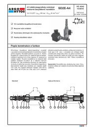
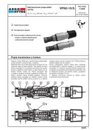
1) <strong>PVS</strong> pumps size 05 and 1 can be mounted<br />
in any positions.<br />
<strong>PVS</strong> pump sizes 2 and 3 must be mounted<br />
with horizontal axis and the compensator<br />
device upward (see figure).<br />
When the pump is installed over the tank<br />
oil level, it is recommended to pay attention<br />
to the inlet pressure (see page 4).<br />
The minimum section of the inlet pipe<br />
must be equal to the section of the thread<br />
inlet port of the pump. The inlet pipes should<br />
be as short as possible, with a small numbers<br />
of bends and without inside section changes.<br />
2) All return and drain pipes must be placed<br />
so that the oil will be not re-sucked directly<br />
from the pump (see figure).<br />
The oil tank must be suitably sized in order to<br />
exchange the thermal power generated to<br />
the system components and to have a low<br />
re-cycle speed.<br />
To ensure maximum pump working life,<br />
inlet oil temperature must never be above<br />
50°C (122°F).<br />
In the systems where the pump runs for a long<br />
time in zero flow setting condition, it is<br />
recommended to install a heat exchanger in the<br />
drain line. The pressure on the drain port must<br />
never be in excess of the specified value (page 4).<br />
The drain pipe must always be independent of<br />
other return lines, connected directly to the tank<br />
and extended sufficiently inside the tank so as<br />
to be below the minimum oil level in order to<br />
avoid generating foam. Moreover, the drain pipe<br />
must be free of restrictions and as far as possible<br />
oleodinamica<br />
3) Motor-pump coupling must be made with a<br />
self-aligning coupling with convex teeth and<br />
with cam in polyamide material.<br />
When assembling, maximum attention must be given<br />
to the distance between the two half-couplings<br />
which must imperatively fall within the value specified<br />
in the diagram below (detail "A").<br />
Other <strong>typ</strong>es of motor - pump couplings are not<br />
permitted.<br />
No induced RADIAL or AXIAL LOADS are allowed<br />
on the pump shaft.<br />
4) During the first installation, the pump must be<br />
run in maximum flow condition (P connected to T),<br />
with the oil flowing directly into the tank, thus to induce<br />
air bleeding.<br />
This phase must go on for several minutes.<br />
Pump priming (oil output to the delivery side) must<br />
occur within a few seconds, otherwise the pump must be<br />
turned off and the operation repeated.<br />
Subsequent start-ups in zero flow setting conditions are<br />
admissible only with pressure not exceeding 30 bar<br />
(435 psi), and at condition that the system and pump<br />
be completely filled up with oil.<br />
During the starting operations, both the first and the<br />
followings, the difference between the oil<br />
temperature and the environment temperature<br />
(body pump temperature) must not exceed by more<br />
than 20°C (68°F).<br />
DETAIL A<br />
4 - 7 [0.157 - 0.276]<br />
away from the inlet pipe. A 0.05 A<br />
IN<br />
DRAIN<br />
200 [8] min<br />
OUT<br />
45°<br />
300 [12] min. 150 [6] min.<br />
Note: dimensions inside [ ] are in inches<br />
For further informations, please consult the leaflet "Installation and start-up instructions for variable displacements vane pumps"<br />
22<br />
50 [2] min