

WAVES AND VIBRATIONS IN INHOMOGENEOUS STRUCTURES ...
WAVES AND VIBRATIONS IN INHOMOGENEOUS STRUCTURES ...
WAVES AND VIBRATIONS IN INHOMOGENEOUS STRUCTURES ...

Create successful ePaper yourself
Turn your PDF publications into a flip-book with our unique Google optimized e-Paper software.
The number of masses in the chain that carry an oscillator<br />
is denoted N. Additionally, a number of masses<br />
without attached oscillators are connected to the chain<br />
at both ends; Nin to the left, and Nout to the right of the<br />
section with oscillators. All oscillators may have different<br />
parameters, denoted βi, ωi, γi and ζi, whereas the<br />
main chain consist of equal springs with stiffness k and<br />
equal masses m. By setting both end masses to m/2<br />
and adding viscous dampers (c = √ mk) we mimic<br />
transparent boundaries at both ends of the chain.<br />
Wave motion is imposed by a time-dependent force<br />
f(t) acting on the leftmost mass in the chain. The specific<br />
force is to be specified in the forthcoming example<br />
sections.<br />
Eqs. (1)–(2) are rewritten in matrix form. We introduce<br />
a vector of the unknown displacements:<br />
u = {u1 u2 . . . uN+Nin+Nout q1 q2 . . . qN } T<br />
and can write the model equations as:<br />
ü + C ˙u + Ku + Fnon(u) = Fext<br />
(3)<br />
(4)<br />
In (4) C is a damping matrix, K is a stiffness matrix,<br />
Fnon is a vector of nonlinear forces and the vector Fext<br />
contains the external load.<br />
3 Numerical simulation of system behavior<br />
The optimization algorithm is based on repeated analyses<br />
of (4), sometimes several hundred, thus a fast and<br />
robust numerical solver is essential. We use a centraldifference<br />
explicit scheme (Cook et al., 2002) that is<br />
very fast and stable with a sufficiently small time step.<br />
In all numerical simulations we use trivial initial conditions<br />
u = ˙u = 0 and the total simulation time is<br />
denoted T .<br />
k<br />
m<br />
Figure 1. Basic unit cell with a mass in the linear main chain and<br />
an attached non-linear oscillator.<br />
f(t)<br />
Figure 2. Finite chain consisting of N masses with attached oscil-<br />
lators, Nin and Nout masses without oscillators in the left and right<br />
end. Viscous dampers are added in the ends to simulate transparent<br />
boundaries.<br />
M<br />
j<br />
k<br />
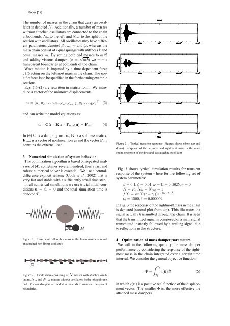
Figure 3. Typical transient response. Figures shows (from top and<br />
down): Response of the leftmost and rightmost mass in the main<br />
chain, response of the first and last attached oscillator.<br />
Fig. 3 shows typical simulation results for transient<br />
response of the system – here for the following set of<br />
system parameters:<br />
β = 0.1, ζ = 0.01, ω = Ω = 0.0625, γ = 0<br />
N = 26, Nin = Nout = 1<br />
f(t) = sin(Ω(t − t0))e −δ(t−t0)2<br />
t0 = 1500, δ = 0.000004<br />
In Fig. 3 the response of the rightmost mass in the chain<br />
is depicted (second plot from top). This illustrates the<br />
signal actually transmitted through the chain. It is seen<br />
that the transmitted signal is composed of a main signal<br />
transmitted instantly followed by a trailing signal due<br />
to reflections in the structure.<br />
4 Optimization of mass damper parameters<br />
We will in the following quantify the mass damper<br />
performance by considering the response of the rightmost<br />
mass in the chain integrated over a certain time<br />
interval. We consider the general objective function:<br />
Φ =<br />
T2<br />
T1<br />
c(u)dt (5)<br />
in which c(u) is a positive real function of the displacement<br />
vector. The smaller Φ is, the more effective the<br />
attached mass dampers.


