WAVES AND VIBRATIONS IN INHOMOGENEOUS STRUCTURES ...
WAVES AND VIBRATIONS IN INHOMOGENEOUS STRUCTURES ...
WAVES AND VIBRATIONS IN INHOMOGENEOUS STRUCTURES ...
Create successful ePaper yourself
Turn your PDF publications into a flip-book with our unique Google optimized e-Paper software.
J. S. Jensen and O. Sigmund Vol. 22, No. 6/June 2005/J. Opt. Soc. Am. B 1193<br />
cell. Thus the entire computational domain consists of<br />
1515+391019 2 =178,695 elements. On a 2.66<br />
-GHz computer with 1-Gbyte RAM, a solution for a single<br />
frequency of Eq. (4) takes approximately 10 s. This is sufficiently<br />
fast for the model to be used in our iterative optimization<br />
algorithm in which several hundred solutions<br />
need to be computed in a single optimization procedure.<br />
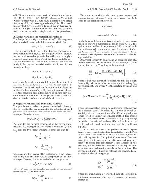
A. Design Variables and Material Interpolation<br />
The design domain D is a subdomain of . We assign one<br />
design variable x e to each finite element within D:<br />
0 x e 1, e D. 6<br />
It is impossible to solve the discrete combinatorial<br />
problem for more than, e.g., 100 design variables. Instead,<br />
we use continuous design variables so that we can apply a<br />
gradient-based algorithm. We let the design variable govern<br />
the distribution of air and dielectric in each element<br />
in D by letting the material coefficients A e and B e vary<br />
linearly with x e:<br />
A e = A 1 + x eA 2 − A 1,<br />
B e = B 1 + x eB 2 − B 1, 7<br />
such that, for x e=0, the material in the element will be<br />
material 1 (air) and, with x e=1, it will be material 2 (dielectric).<br />
It is now the task for the optimization algorithm<br />
to identify the values of x e in D that optimize our chosen<br />
objective function and, additionally, to ensure only discrete<br />
values, 0 and 1, of the design variables in the final<br />
design in order to obtain a well-defined structure.<br />
B. Objective Function and Sensitivity Analysis<br />
The goal is to maximize the power transmission through<br />
the waveguide, thereby minimizing the reflection at the T<br />
junction. The power transmission is found from the timeaveraged<br />
Poynting vector:<br />
Px = PxPyT = 1<br />
ARiū u. 8<br />
2<br />
We consider the vertical component of the power transmission,<br />
P y, averaged in two separate domains J1 and<br />
J2 near the two output waveguide ports [see Fig. 1]:<br />
J1 = 1<br />
e Py, Ny eJ1 J 2 =− 1<br />
N y<br />
e Py, 9<br />
eJ2 where N y are the number of finite elements in the y direction<br />
in J1 and J2 . The vertical component of the timeaveraged<br />
Poynting vector in each element is given as<br />
e 1<br />
Py =<br />
2 AeRiue T e e Qyū , 10<br />
where ūe denotes the complex conjugate of the element<br />
e<br />
nodal values. Qy is defined as<br />
e<br />
Qy = NT<br />
y NdS y=0. 11<br />
We want to maximize the total power transmitted<br />
through the output ports for a given frequency , which<br />
leads to the optimization problem:<br />
max J,<br />
xe J = J 1 + J 2, 12<br />
in which we additionally enforce a simple symmetry condition<br />
to ensure a symmetrical design with J 1=J 2. The<br />
optimization problem in expressions (12) is solved with<br />
the mathematical programming tool, the Method of Moving<br />
Asymptotes, 17 in combination with the computed sensitivities<br />
of the objective function with respect to the design<br />
variables.<br />
Analytical sensitivity analysis is an essential part of a<br />
fast optimization method and can be performed, e.g., with<br />
the adjoint method, 12 leading to the expression<br />
dJ<br />
dx e<br />
=2RTd− 2M + iC + K<br />
u, 13<br />
dxe where it has been assumed for simplicity that the design<br />
domain D neither includes the wave input boundary inp<br />
nor overlaps J and where is the solution to the adjoint<br />
problem<br />
− 2M + iC + KT = i<br />
4 e e T T e AeQy − Qy ū ,<br />
eJ 14<br />
where the summation should be understood in the normal<br />
finite-element sense. Note that Eq. (14) can be solved essentially<br />
without computational effort if the original problem<br />
is solved by a direct factorization method. This means<br />
that one can obtain all the sensitivities [Eq. (13)] simply<br />
by solving the original problem [Eq. (4)] with an extra<br />
right-hand side (load case) and inserting the result into<br />
Eq. (13).<br />
In structural mechanics the problem of mesh dependency<br />
arises when the standard formulation is used. This<br />
implies that if the finite-element mesh is refined, finer details<br />
will appear in the optimized structure. One can<br />
avoid this by introducing a heuristic mesh-independency<br />
filter. 12 In optics this dependency is not inherent in the<br />
problem, but the filter can nevertheless be applied with<br />
advantage to avoid too fine details in the structure. The<br />
variant used here is based on filtering the computed sensitivities<br />
in the following way:<br />
dJ ˆ<br />
=<br />
dxe ˆ<br />
H e<br />
dJ<br />
Hˆ e<br />
dxe , 15<br />
where the summation is performed over all elements in<br />
the design domain and where Hˆ i is a convolution operator<br />
defined as


