

WAVES AND VIBRATIONS IN INHOMOGENEOUS STRUCTURES ...
WAVES AND VIBRATIONS IN INHOMOGENEOUS STRUCTURES ...
WAVES AND VIBRATIONS IN INHOMOGENEOUS STRUCTURES ...

Create successful ePaper yourself
Turn your PDF publications into a flip-book with our unique Google optimized e-Paper software.
In all the examples shown a density filter is used in<br />
order to avoid checkerboard structures (Guest et al.<br />
2004; Sigmund 2007). The method of moving asymptotes<br />
(Svanberg 1987) is used for the optimization.<br />
6 Examples: vibration response<br />
In this section we show examples of plates optimized<br />
with the objective of minimizing the overall response<br />
given by (41). The structure to be optimized is a simply<br />
supported plate subjected to a harmonic point load in<br />
the center. The plate is 0.5 × 0.5 m, has a thickness of<br />
3 mm and is made from steel and polycarbonate with a<br />
maximum allowed fraction of steel of 25%. There is no<br />
damping included.<br />
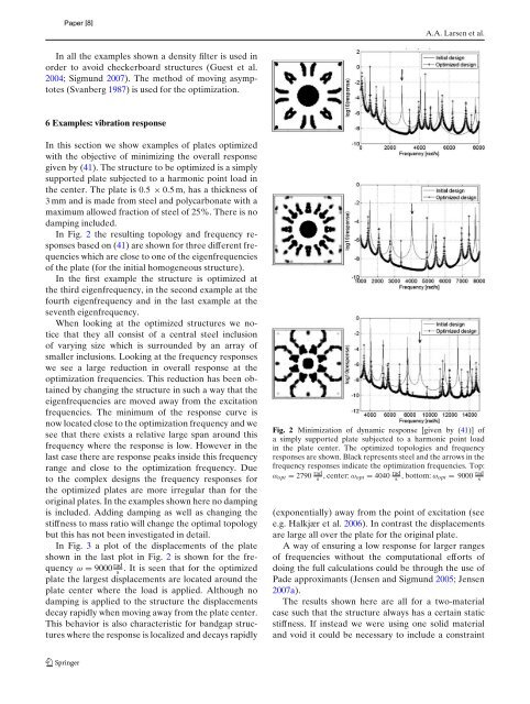
In Fig. 2 the resulting topology and frequency responses<br />
based on (41) are shown for three different frequencies<br />
which are close to one of the eigenfrequencies<br />
of the plate (for the initial homogeneous structure).<br />
In the first example the structure is optimized at<br />
the third eigenfrequency, in the second example at the<br />
fourth eigenfrequency and in the last example at the<br />
seventh eigenfrequency.<br />
When looking at the optimized structures we notice<br />
that they all consist of a central steel inclusion<br />
of varying size which is surrounded by an array of<br />
smaller inclusions. Looking at the frequency responses<br />
we see a large reduction in overall response at the<br />
optimization frequencies. This reduction has been obtained<br />
by changing the structure in such a way that the<br />
eigenfrequencies are moved away from the excitation<br />
frequencies. The minimum of the response curve is<br />
now located close to the optimization frequency and we<br />
see that there exists a relative large span around this<br />
frequency where the response is low. However in the<br />
last case there are response peaks inside this frequency<br />
range and close to the optimization frequency. Due<br />
to the complex designs the frequency responses for<br />
the optimized plates are more irregular than for the<br />
original plates. In the examples shown here no damping<br />
is included. Adding damping as well as changing the<br />
stiffness to mass ratio will change the optimal topology<br />
but this has not been investigated in detail.<br />
In Fig. 3 a plot of the displacements of the plate<br />
shown in the last plot in Fig. 2 is shown for the frequency<br />
ω = 9000 rad<br />
. It is seen that for the optimized<br />
s<br />
plate the largest displacements are located around the<br />
plate center where the load is applied. Although no<br />
damping is applied to the structure the displacements<br />
decay rapidly when moving away from the plate center.<br />
This behavior is also characteristic for bandgap structures<br />
where the response is localized and decays rapidly<br />
A.A. Larsen et al.<br />
Fig. 2 Minimization of dynamic response [given by (41)] of<br />
a simply supported plate subjected to a harmonic point load<br />
in the plate center. The optimized topologies and frequency<br />
responses are shown. Black represents steel and the arrows in the<br />
frequency responses indicate the optimization frequencies. Top:<br />
ωopt = 2790 rad<br />
s ,center:ωopt = 4040 rad<br />
s , bottom: ωopt = 9000 rad<br />
s<br />
(exponentially) away from the point of excitation (see<br />
e.g. Halkjær et al. 2006). In contrast the displacements<br />
are large all over the plate for the original plate.<br />
A way of ensuring a low response for larger ranges<br />
of frequencies without the computational efforts of<br />
doing the full calculations could be through the use of<br />
Pade approximants (Jensen and Sigmund 2005; Jensen<br />
2007a).<br />
The results shown here are all for a two-material<br />
case such that the structure always has a certain static<br />
stiffness. If instead we were using one solid material<br />
and void it could be necessary to include a constraint


