

WAVES AND VIBRATIONS IN INHOMOGENEOUS STRUCTURES ...
WAVES AND VIBRATIONS IN INHOMOGENEOUS STRUCTURES ...
WAVES AND VIBRATIONS IN INHOMOGENEOUS STRUCTURES ...

Create successful ePaper yourself
Turn your PDF publications into a flip-book with our unique Google optimized e-Paper software.
Topological material layout in plates for vibration suppression and wave propagation control<br />
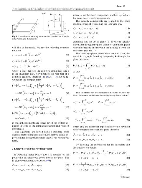
Fig. 1 Plate element showing rotations and translations. Coordinate<br />
system and dimensions<br />
will also be harmonic. We use the following complex<br />
notation<br />
<br />
ψx(x, y, t) =ℜ ˜ψx(x, y)e iωt<br />
(6)<br />
<br />
ψy(x, y, t) =ℜ ˜ψy(x, y)e iωt<br />
(7)<br />
w(x, y, t) =ℜ iωt<br />
˜w(x, y)e (8)<br />
in which the moments and forces have been written explicitly<br />
in terms of the complex deflection and rotation<br />
amplitudes.<br />
The equations are solved using a standard finite<br />
element method implementation, but first we derive expressions<br />
for energy transport in the plate in continuous<br />
form.<br />
3 Energy flow and the Poynting vector<br />
The Poynting vector P(x, y, z, t) is a measure of the<br />
point-wise instantaneous power flow in the plate. The<br />
in-plane components are (Auld 1973)<br />
Px =−σxx ˙ dx − σyx ˙ dy − σzx ˙ dz<br />
Py =−σxy ˙ dx − σyy ˙ dy − σzy ˙ dz<br />
(12)<br />
(13)<br />
where σij are the stress components and { ˙ dx, ˙ dy, ˙ dz} are<br />
the point-wise velocity components.<br />
The velocity components are related to the plate<br />
model degrees-of-freedom in the following way<br />
˙dx(x, y, z) =−z˙ψx(x, y) (14)<br />
˙dy(x, y, z) =−z ˙ψy(x, y) (15)<br />
˙dz(x, y, z) = ˙w(x, y) (16)<br />
assuming that the out-of-plane (z−direction) velocity<br />
is constant through the plate thickness and the in-plane<br />
velocities depend linearly with the distance z from the<br />
mid-plane (see Fig. 1).<br />
The total xy−plane power flow per unit area, denoted<br />
ˆP(x, y, t), is found by integrating P through the<br />
plate thickness:<br />
ˆP(x, y, t) =<br />
h/2<br />
−h/2<br />
P(x, y, z, t)dz (17)<br />
where a tilde denotes the complex amplitudes and i<br />
is the imaginary unit. ℜ symbolizes the real part of a<br />
complex quantity. Inserting (4)–(8), (1)–(3) canberewritten<br />
in the complex form<br />
<br />
D ˜ψx,x + ν ˜ψy,y<br />
,x +<br />
<br />
1 − ν<br />
2 D<br />
<br />
˜ψx,y + ˜ψy,x<br />
<br />
,y<br />
<br />
+ kGh ˜w,x − ˜ψx<br />
2 ρh3<br />
+ ω<br />
12 ˜ψx = 0 (9)<br />
<br />
D ˜ψy,y + ν ˜ψx,x<br />
,y +<br />
<br />
1 − ν<br />
2 D<br />
<br />
˜ψy,x + ˜ψx,y<br />
<br />
,x<br />
<br />
+ kGh ˜w,y − ˜ψy<br />
2 ρh3<br />
+ ω<br />
12 ˜ψy = 0 (10)<br />
<br />
kGh ˜w,x − ˜ψx<br />
,x +<br />
<br />
kGh ˜w,y − ˜ψy<br />
,y<br />
+ ω 2 so that<br />
ˆPx =<br />
ˆPy =<br />
ρh ˜w = 0 (11)<br />
The integrals can be expressed in terms of the defined<br />
moments and shear forces by using the relations<br />
h/2<br />
h/2<br />
Mx = σxxzdz, My = σyyzdz,<br />
−h/2<br />
−h/2<br />
h/2<br />
Mxy = σyxzdz,<br />
−h/2<br />
h/2<br />
h/2<br />
Tx = σzxdz, Ty = σzydz, (20)<br />
h/2<br />
(σxxz ˙ψx + σyxz ˙ψy − σzx ˙w)dz (18)<br />
−h/2<br />
h/2<br />
(σxyz ˙ψx + σyyz ˙ψy − σzy ˙w)dz (19)<br />
−h/2<br />
−h/2<br />
−h/2<br />
which give the following expressions for the Poynting<br />
vector integrated through the plate thickness<br />
ˆPx = Mx ˙ψx + Mxy ˙ψy − Tx ˙w (21)<br />
ˆPy = Myx ˙ψx + My ˙ψy − Ty ˙w (22)<br />
By inserting the expressions for the moments and<br />
shear forces we obtain<br />
1 − ν<br />
ˆPx =−D(ψx,x + νψy,y) ˙ψx −<br />
2 D(ψx,y + ψy,x) ˙ψy<br />
+ kGh(ψx − w,x) ˙w (23)<br />
1 − ν<br />
ˆPy =−<br />
2 D(ψx,y + ψy,x) ˙ψx − D(νψx,x + ψy,y) ˙ψy<br />
+ kGh(ψy − w,y) ˙w (24)


