

WAVES AND VIBRATIONS IN INHOMOGENEOUS STRUCTURES ...
WAVES AND VIBRATIONS IN INHOMOGENEOUS STRUCTURES ...
WAVES AND VIBRATIONS IN INHOMOGENEOUS STRUCTURES ...

You also want an ePaper? Increase the reach of your titles
YUMPU automatically turns print PDFs into web optimized ePapers that Google loves.
904 S. Halkjær, O. Sigmund and J. S. Jensen<br />
log(T)<br />
0<br />
-10<br />
-20<br />
-30<br />
-40<br />
-50<br />
-60<br />
-70<br />
ture. Here, the periodicity of the structure has been chosen<br />
to be 8 cm which corresponds to dx 1.546 m. It is noted<br />
that the results compare well with the results obtained in<br />
the previous section for the 2D crystals. Studying the optimized<br />
topology in Fig. 13 reveals that the Aluminum to<br />
base cell size ratio is approximately 0.42 – exactly like the<br />
result obtained for an infinite periodic medium in Fig. 7.<br />
One may also compare the dispersion diagram in Fig. 7<br />
and the transmission spectrum in Fig. 13 and find nearly<br />
perfect agreement as should be expected.<br />
Case of dx<br />
long.<br />
shear<br />
0 5 10 15 20 25 30<br />
Frequency [kHz]<br />
Fig. 13. Top: optimized design for a plane shear wave propagating<br />
from left to right. Design domain dimensions: dx ¼ 10 2pcs=w and<br />
dy ¼ dx=10. Bottom: corresponding transmission spectrum for a shear<br />
and a longitudinal wave (periodicity of the design chosen to be 8 cm).<br />
a b<br />
Fig. 14. Optimized designs for the case of dx ¼ 2 2pcs=w and<br />
dy ¼ dx. (a): longitudinal wave, (b): shear wave.<br />
wavelength<br />
The slab dimension is now reduced so that<br />
dx ¼ 2 2pcs=w, i.e. the axial dimension is just two wavelengths<br />
of a shear wave. The slab section height is<br />
doubled so that the design domain now is quadratic<br />
(dy ¼ dx).<br />
Instead of considering only a single plane wave, we<br />
now optimize the design for five different waves simultaneously.<br />
Each wave propagates from x ¼ 0 but only from<br />
1/5th of the section height. In this way we can ensure that<br />
the resulting design reflects incoming waves from multiple<br />
directions. Additionally, we treat waves propagating both<br />
from left to right and vice versa, so that a total of 10 load<br />
cases are treated.<br />
Figure 14 shows the optimized designs obtained for a<br />
longitudinal wave and for a shear wave, separately. It is<br />
apparent that the designs are no longer periodic-like but<br />
are strongly influenced by the limited axial dimension.<br />
The wavelength of the longitudinal wave is longer than the<br />
shear wavelength (cc ¼ ffiffiffiffiffiffiffiffiffiffiffiffiffiffiffiffiffiffiffiffiffiffiffiffiffiffiffiffiffiffiffiffiffiffiffiffi<br />
p<br />
ð2 2nÞ=ð1 2nÞ cs ¼ ffiffi p<br />
6 cs<br />
for material 1), which implies that dx is less that a single<br />
a b<br />
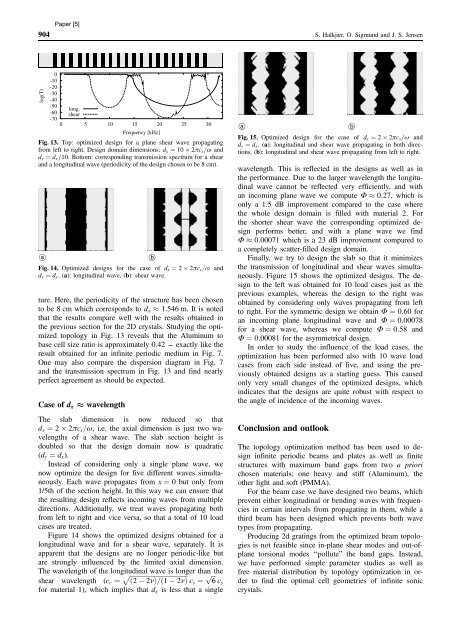
Fig. 15. Optimized design for the case of dx ¼ 2 2pcs=w and<br />
dy ¼ dx. (a): longitudinal and shear wave propagating in both directions,<br />
(b): longitudinal and shear wave propagating from left to right.<br />
wavelength. This is reflected in the designs as well as in<br />
the performance. Due to the larger wavelength the longitudinal<br />
wave cannot be reflected very efficiently, and with<br />
an incoming plane wave we compute F 0:27, which is<br />
only a 1.5 dB improvement compared to the case where<br />
the whole design domain is filled with material 2. For<br />
the shorter shear wave the corresponding optimized design<br />
performs better, and with a plane wave we find<br />
F 0:00071 which is a 23 dB improvement compared to<br />
a completely scatter-filled design domain.<br />
Finally, we try to design the slab so that it minimizes<br />
the transmission of longitudinal and shear waves simultaneously.<br />
Figure 15 shows the optimized designs. The design<br />
to the left was obtained for 10 load cases just as the<br />
previous examples, whereas the design to the right was<br />
obtained by considering only waves propagating from left<br />
to right. For the symmetric design we obtain F ¼ 0:60 for<br />
an incoming plane longitudinal wave and F ¼ 0:00078<br />
for a shear wave, whereas we compute F ¼ 0:58 and<br />
F ¼ 0:00081 for the asymmetrical design.<br />
In order to study the influence of the load cases, the<br />
optimization has been performed also with 10 wave load<br />
cases from each side instead of five, and using the previously<br />
obtained designs as a starting guess. This caused<br />
only very small changes of the optimized designs, which<br />
indicates that the designs are quite robust with respect to<br />
the angle of incidence of the incoming waves.<br />
Conclusion and outlook<br />
The topology optimization method has been used to design<br />
infinite periodic beams and plates as well as finite<br />
structures with maximum band gaps from two a priori<br />
chosen materials; one heavy and stiff (Aluminum), the<br />
other light and soft (PMMA).<br />
For the beam case we have designed two beams, which<br />
prevent either longitudinal or bending waves with frequencies<br />
in certain intervals from propagating in them, while a<br />
third beam has been designed which prevents both wave<br />
types from propagating.<br />
Producing 2d gratings from the optimized beam topologies<br />
is not feasible since in-plane shear modes and out-ofplane<br />
torsional modes ‘‘pollute” the band gaps. Instead,<br />
we have performed simple parameter studies as well as<br />
free material distribution by topology optimization in order<br />
to find the optimal cell geometries of infinite sonic<br />
crystals.


