

WAVES AND VIBRATIONS IN INHOMOGENEOUS STRUCTURES ...
WAVES AND VIBRATIONS IN INHOMOGENEOUS STRUCTURES ...
WAVES AND VIBRATIONS IN INHOMOGENEOUS STRUCTURES ...

You also want an ePaper? Increase the reach of your titles
YUMPU automatically turns print PDFs into web optimized ePapers that Google loves.
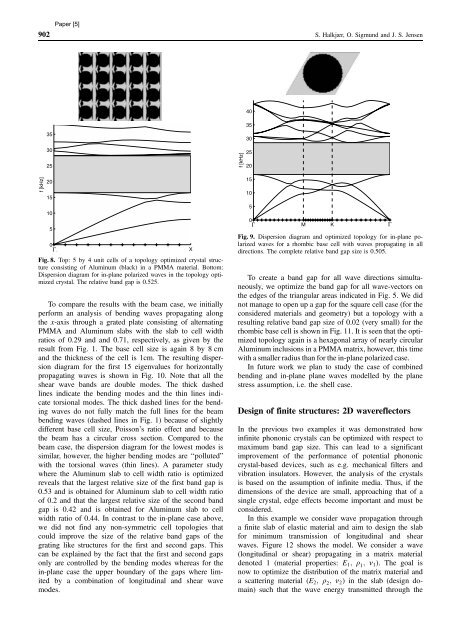
902 S. Halkjær, O. Sigmund and J. S. Jensen<br />
f [kHz]<br />
35<br />
30<br />
25<br />
20<br />
15<br />
10<br />
5<br />
0<br />
GΓ X<br />
Fig. 8. Top: 5 by 4 unit cells of a topology optimized crystal structure<br />
consisting of Aluminum (black) in a PMMA material. Bottom:<br />
Dispersion diagram for in-plane polarized waves in the topology optimized<br />
crystal. The relative band gap is 0.525.<br />
To compare the results with the beam case, we initially<br />
perform an analysis of bending waves propagating along<br />
the x-axis through a grated plate consisting of alternating<br />
PMMA and Aluminum slabs with the slab to cell width<br />
ratios of 0.29 and and 0.71, respectively, as given by the<br />
result from Fig. 1. The base cell size is again 8 by 8 cm<br />
and the thickness of the cell is 1cm. The resulting dispersion<br />
diagram for the first 15 eigenvalues for horizontally<br />
propagating waves is shown in Fig. 10. Note that all the<br />
shear wave bands are double modes. The thick dashed<br />
lines indicate the bending modes and the thin lines indicate<br />
torsional modes. The thick dashed lines for the bending<br />
waves do not fully match the full lines for the beam<br />
bending waves (dashed lines in Fig. 1) because of slightly<br />
different base cell size, Poisson’s ratio effect and because<br />
the beam has a circular cross section. Compared to the<br />
beam case, the dispersion diagram for the lowest modes is<br />
similar, however, the higher bending modes are ‘‘polluted”<br />
with the torsional waves (thin lines). A parameter study<br />
where the Aluminum slab to cell width ratio is optimized<br />
reveals that the largest relative size of the first band gap is<br />
0.53 and is obtained for Aluminum slab to cell width ratio<br />
of 0.2 and that the largest relative size of the second band<br />
gap is 0.42 and is obtained for Aluminum slab to cell<br />
width ratio of 0.44. In contrast to the in-plane case above,<br />
we did not find any non-symmetric cell topologies that<br />
could improve the size of the relative band gaps of the<br />
grating like structures for the first and second gaps. This<br />
can be explained by the fact that the first and second gaps<br />
only are controlled by the bending modes whereas for the<br />
in-plane case the upper boundary of the gaps where limited<br />
by a combination of longitudinal and shear wave<br />
modes.<br />
f [kHz]<br />
40<br />
35<br />
30<br />
25<br />
20<br />
15<br />
10<br />
5<br />
0<br />
GΓ M K GΓ<br />
Fig. 9. Dispersion diagram and optimized topology for in-plane polarized<br />
waves for a rhombic base cell with waves propagating in all<br />
directions. The complete relative band gap size is 0.505.<br />
To create a band gap for all wave directions simultaneously,<br />
we optimize the band gap for all wave-vectors on<br />
the edges of the triangular areas indicated in Fig. 5. We did<br />
not manage to open up a gap for the square cell case (for the<br />
considered materials and geometry) but a topology with a<br />
resulting relative band gap size of 0.02 (very small) for the<br />
rhombic base cell is shown in Fig. 11. It is seen that the optimized<br />
topology again is a hexagonal array of nearly circular<br />
Aluminum inclusions in a PMMA matrix, however, this time<br />
with a smaller radius than for the in-plane polarized case.<br />
In future work we plan to study the case of combined<br />
bending and in-plane plane waves modelled by the plane<br />
stress assumption, i.e. the shell case.<br />
Design of finite structures: 2D wavereflectors<br />
In the previous two examples it was demonstrated how<br />
infinite phononic crystals can be optimized with respect to<br />
maximum band gap size. This can lead to a significant<br />
improvement of the performance of potential phononic<br />
crystal-based devices, such as e.g. mechanical filters and<br />
vibration insulators. However, the analysis of the crystals<br />
is based on the assumption of infinite media. Thus, if the<br />
dimensions of the device are small, approaching that of a<br />
single crystal, edge effects become important and must be<br />
considered.<br />
In this example we consider wave propagation through<br />
a finite slab of elastic material and aim to design the slab<br />
for minimum transmission of longitudinal and shear<br />
waves. Figure 12 shows the model. We consider a wave<br />
(longitudinal or shear) propagating in a matrix material<br />
denoted 1 (material properties: E1; q 1; n1). The goal is<br />
now to optimize the distribution of the matrix material and<br />
a scattering material (E2; q 2; n2) in the slab (design domain)<br />
such that the wave energy transmitted through the


