Multi-link suspension analysis: An elastokinematic ... - ArchiMeDes
Multi-link suspension analysis: An elastokinematic ... - ArchiMeDes
Multi-link suspension analysis: An elastokinematic ... - ArchiMeDes

Create successful ePaper yourself
Turn your PDF publications into a flip-book with our unique Google optimized e-Paper software.
Introduction<br />
29 th ISATA - Florence, Italy, 3 rd - 6 th June 1996 - 96VR031<br />
<strong>Multi</strong>-<strong>link</strong> <strong>suspension</strong> <strong>analysis</strong>:<br />
<strong>An</strong> <strong>elastokinematic</strong> model<br />
Danilo Cambiaghi, Marco Gadola, David Vetturi, Luca Manzo<br />
Mechanical Engineering Dept. - University of Brescia<br />
Via Branze 38, 25123 Brescia - Italy<br />
tel. ++39.30.3715426 fax ++39.30.3702448<br />
e-mail: gadola@bsing.ing.unibs.it<br />
96VR031<br />
<strong>Multi</strong>-<strong>link</strong> <strong>suspension</strong>s are the latest development in road car chassis design. They are conceived<br />
to provide high stiffness in the lateral direction and a reasonable compliance in the fore/aft<br />
(longitudinal) direction. This is due to the need of ensuring a good ride quality without affecting<br />
handling and safety.<br />
Ellis defines compliance as “The change in <strong>suspension</strong> characteristics due to external forces” ( 1 ).<br />
The <strong>elastokinematic</strong> characteristics are usually tuned up to minimise camber and track changes and<br />
correctly tune toe variations. At the rear axle of a rear-drive car the central axis of elasticity can be<br />
positioned properly to result in a toe-in tendency under throttle-off condition, thus improving<br />
stability. The front axle of a front-drive car can be designed with a "virtual steering axis" to<br />
optimise the steering geometry. The paper presents the application of a simple algorithm for the<br />
force-displacement <strong>analysis</strong> of a five-rod <strong>suspension</strong> which allows for rubber bushing compliance.<br />
<strong>Multi</strong>-<strong>link</strong> geometry: advantages<br />
The tyre/road interface is a source of vibration which can heavily affect the ride comfort in a<br />
passenger car. Moreover, the radial-type tire is structurally stiffer than its cross-ply predecessor<br />
hence more prone to generate noise and harshness. As Bastow states ( 2 ) “it has long been realised<br />
that road noise finds its way into the car through the <strong>suspension</strong> system and that rubber in each of<br />
the paths from wheel to car structure could provide a barrier (...)”. Providing some compliance with<br />
the use of rubber bushings (the so-called silent-blocks) at the chassis end of the <strong>suspension</strong> arms<br />
can be an effective way to improve the comfort level but care has to be taken to avoid a flexibility<br />
excess.<br />
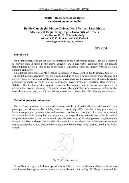
Fig. 1 - five-<strong>link</strong> scheme<br />
Generally speaking a multi-<strong>link</strong> <strong>suspension</strong> is usually a five-rod mechanism which can be seen as<br />
a double-wishbone system whose arms are split at the outer apices (Fig. 1). The geometry and the
29 th ISATA - Florence, Italy, 3 rd - 6 th June 1996 - 96VR031<br />
rubber bush elasticity can be properly tuned to minimise camber and track changes and obtain the<br />
desired toe variations. At the rear axle of a RWD car the central axis of elasticity can be positioned<br />
properly to result in a toe-in tendency under throttle-off condition, thus improving stability and a<br />
slight toe-out tendency under power to improve the handling characterictics. The front axle can be<br />
designed with a "virtual steering axis" to optimise the steering geometry and minimise castor<br />
variation under traction in a front-drive car.<br />
The multi-<strong>link</strong> system offers total flexibility of wheel/body movement control, lift, squat and dive<br />
compensation, and mounting point placement with low unsprung mass figures. This can be<br />
achieved provided that an advanced computer model is available to the designer, since a multi-<strong>link</strong><br />
can not be studied with the use of traditional drafting methods. A closed-form solution model is not<br />
very handy either since it requires the solution of a 20 th degree polynomial equation in a single<br />
unknown.<br />
Quite a few papers have been written on the subject (see ( 3 ), ( 4 ), ( 5 )). This paper deals with the<br />
application of a simple numerical method for the force-displacement <strong>analysis</strong> of the five-rod<br />
<strong>suspension</strong> which allows for rubber bushing compliance.<br />
Previous papers have presented the computation of a double-wishbone, ball joint-mounted racing<br />
car <strong>suspension</strong> ( 6 ), ( 7 ), ( 8 ). In that case <strong>suspension</strong> kinematics and component compliance were<br />
analysed in a three-step process : geometry solution, force equilibrium, and compliance <strong>analysis</strong>,<br />
where “compliance” means that not only the spring but also the <strong>suspension</strong> arms were considered<br />
elastic i.e compliant. This sort of process can be used to study a five-<strong>link</strong> <strong>suspension</strong> as well ; in this<br />
case “compliance” stays for rubber bushing as well as spring elastic deflection because the<br />
<strong>suspension</strong> arm deflection is negligible.<br />
Geometry solution<br />
Inputs to the first step are the <strong>suspension</strong> node co-ordinate array and a spring deflection value s,<br />
either in bump or in droop. The node co-ordinate array fully describes the static <strong>suspension</strong><br />
geometry i.e. the so-called “design configuration”. The chassis is held still while the spring is<br />
deflected by the given amount s and the wheel is displaced accordingly provided the movement is<br />
within the mechanical limits. The procedure leads to determination of all moving nodes new coordinates<br />
and outputs the altered node array as a function of s. In the double-wishbone case basic,<br />
closed-form stereometry formulas were employed (Fig. 2).<br />
Wheel<br />
displacement 's'<br />
Node co-ordinates<br />
STEREOMETRY<br />
new configuration= f(s):<br />
Displaced node co-ordinates<br />
Fig. 2 - geometry solution, double wishbone case
29 th ISATA - Florence, Italy, 3 rd - 6 th June 1996 - 96VR031<br />
A multi-<strong>link</strong> system can be seen as an in-parallel five-rod mechanism which can be studied with<br />
the same methods which are commonly applied to platform robots ( 9 ), ( 10 ). The chassis can be seen<br />
as the ground (where the global co-ordinate system is placed) while the wheel-upright assembly can<br />
be seen as the moving part of the system (where a local co-ordinate system is placed). In the<br />
simplest case the upright is connected to the chassis by five fixed-length rods plus one variablelength<br />
rod (the spring-damper unit).<br />
If well-designed this sort of mechanism can give a continuous solution in the working range hence<br />
the <strong>analysis</strong> can be based on a simple application of Taylor’s formula around the known static<br />
position. A rigid body in a 3-D space has 6 d.o.f. therefore the local reference system can be defined<br />
with the use of 6 parameters. The typical wheel angles α (castor), β (toe) and γ (camber) can be<br />
used to define the axis rotations while the wheel center co-ordinates X, Y, Z can define the relative<br />
origin position.<br />
T<br />
Now if the 6x1 parameter vector is S 0 = [ α β γ X Y Z] = [ s1 K s6]<br />
, a 4x4<br />
rototranslation matrix M0 = M(S0) can be written in the initial “design configuration” to compute<br />
the global co-ordinates (x0, y0, z0) starting from the local co-ordinates (x’0, y’0, z’0) for any point:<br />
⎡x<br />
0 ⎤ ⎡x'<br />
0 ⎤<br />
⎡ Cβ⋅Cα −Sβ −Cβ⋅Sα X⎤<br />
⎢<br />
y<br />
⎥ ⎢<br />
0 y'<br />
⎥<br />
⎢<br />
⎢ ⎥<br />
0<br />
Cγ ⋅Sβ⋅Cα −Sγ ⋅Sα Cγ ⋅Cβ −Cγ ⋅Sβ⋅Sα −Cα⋅Sγ Y<br />
⎥<br />
= M ⋅⎢<br />
⎥ where M = ⎢<br />
⎥<br />
⎢z<br />
0 ⎥ ⎢z'<br />
0 ⎥<br />
⎢Sγ<br />
⋅Sβ⋅ Cα + Cγ ⋅Sα Sγ ⋅Cβ −Sγ ⋅Sβ⋅ Sα + Cα⋅Cγ Z⎥<br />
⎢ ⎥ ⎢ ⎥<br />
⎢<br />
⎥<br />
⎣ 1 ⎦ ⎣ 1 ⎦<br />
⎣ 0 0 0 1⎦<br />
“Sα” stays for “sinα”, “Cα” stays for “cosα”, and the last line is added to define both translation<br />
and rotation with the same matrix. Also the <strong>suspension</strong> joints on the chassis (global co-ordinates)<br />
and on the upright (local co-ordinates) can be represented in matrix notation:<br />
A i<br />
⎡ X i ⎤<br />
⎢<br />
Y<br />
⎥<br />
i<br />
= ⎢ ⎥<br />
⎢ Z ⎥<br />
⎢<br />
⎣ 1<br />
i<br />
⎥<br />
⎦i<br />
= 1... 6<br />
(chassis joints, global co-ords) B i<br />
⎡x'<br />
i ⎤<br />
⎢<br />
y'<br />
⎥<br />
i<br />
= ⎢ ⎥<br />
⎢z'<br />
⎥<br />
⎢<br />
⎣ 1<br />
i<br />
⎥<br />
⎦i<br />
= 1... 6<br />
(upright joints, local co-ords)<br />
and, applying the rototranslation matrix: Ci = M⋅ Bi<br />
for i=1...6 (upright joints, global co-ords).<br />
Now the <strong>link</strong> length vector can be written as follows: Q [ ]<br />
T<br />
= d1 d2 d3 d4 d5 d6<br />
where the<br />
distances between joints can be computed as a 2 nd order norm :<br />
di = M⋅Bi − Ai = Ci −A<br />
i for i=1...6<br />
In the five-<strong>link</strong> <strong>suspension</strong> case d1, d2, d3, d4 and d5 are constant values while the spring length d6<br />
is a variable. In the design configuration S0, d6 is known hence Q0 = F(S0) is a known function.<br />
When a small deflection is applied to d6, Taylor's series can be used to write :<br />
Q≅ ( S ) + ⋅( S−S )<br />
S F<br />
∂ F<br />
∂ F<br />
0 0 or ( Q−Q0) ≅ ⋅( S−S0) ∂<br />
∂ S<br />
(Q-Q0) represents the spring length variation, (S-S0) is the unknown term and represents the<br />
motion between the design configuration and the new position, and the 6x6 matrix ∂F/∂S is the socalled<br />
Jacobian matrix J, whose terms look like<br />
∂ d d ( s s ds s ) d ( s s s<br />
i i 1... j + j... 6 − i 1... j...<br />
6)<br />
Jij<br />
= ≅<br />
∂ s<br />
ds<br />
j<br />
j
29 th ISATA - Florence, Italy, 3 rd - 6 th June 1996 - 96VR031<br />
J can be computed by writing the analytical equations or approximated by giving very small<br />
increments to each parameter sj of S [ ]<br />
T<br />
= α β γ X Y Z then computing the length<br />
variation di for each <strong>link</strong>. This method is usually quicker.<br />
Now an iterative process can be started. A linear system<br />
∂ F<br />
( Q− QK)<br />
= ⋅∆<br />
S K with QK=F(SK)<br />
∂ S<br />
must be solved at each step until Q− F( SK)<br />
≤ε<br />
. It should be noted that small wheel displacement<br />
steps make a quick and precise computation easier.<br />
Force equilibrium<br />
Rigid body<br />
load set 'F'<br />
Node co-ordinates<br />
EQUILIBRIUM EQUATIONS<br />
Restraint reactions<br />
Fig. 5 - force equilibrium<br />
The <strong>suspension</strong> is considered locked in its actual position e.g. the design configuration. As stated<br />
before the wheel/upright assembly has 6 d.o.f. in a 3-D space. In the multi-<strong>link</strong> case it is restrained<br />
by six pin-ended <strong>link</strong>s : each <strong>link</strong> is equivalent to one restraint, thus reducing the structure from<br />
redundant (indeterminate) to isostatic (determinate).<br />
Node co-ordinates<br />
Wheel load set 'F'<br />
iteration<br />
FORCE EQUILIBRIUM<br />
Axial loads<br />
Spring and bushing<br />
properties<br />
Fig. 6 - compliance module<br />
Spring and rubber bushing<br />
deflections<br />
N<br />
GEOMETRY SOLUTION<br />
New node co-ordinates<br />
convergence?<br />
Y<br />
Main geometry parameters
29 th ISATA - Florence, Italy, 3 rd - 6 th June 1996 - 96VR031<br />
Orientation hence direction cosines are known for each <strong>link</strong>. <strong>An</strong>y load set can be applied at the<br />
wheel/road surface interface (accelerating, braking, turning, crossing a bump) and six equilibrium<br />
equations in six unknowns i.e. axial forces are obtained. This set of simultaneous equations is<br />
solved with the Gauss-Jordan method (Fig. 5).<br />
Compliance <strong>analysis</strong><br />
Now both the kinematic behaviour and the force distribution are known. But when it comes to<br />
determine spring and rubber bushing deflection when the wheel is laden, a deterministic solution is<br />
impossible due to non-linearities like the <strong>suspension</strong> ratio. It is possible to overcome the nonlinearity<br />
by <strong>link</strong>ing the previously seen modules through an iterative process. When a load case is<br />
given (braking, turning etc. as before) the load on the coil spring as well as on each silent-block can<br />
be determined by running the force equilibrium module. The deformed geometry can be computed<br />
by deflecting each elastic component. If coil spring deflection will probably be the most important<br />
contribution to wheel displacement also elastic joint effects (compliance) will upset wheel position<br />
by a certain amount. This leads to a new geometry hence a new load distribution through the<br />
system. The process must then be restarted to compute the consequent load distribution and altered<br />
geometry until the iteration converges (Fig. 6).<br />
Conclusion<br />
A method for solving the multi-<strong>link</strong> <strong>suspension</strong> problem is presented. It is fairly straightforward<br />
and enables the designer to fully understand the <strong>suspension</strong> behaviour under road loads with the use<br />
of a simple PC program. A comprehensive, windows-based software and a case study will be<br />
presented in the near future.<br />
References<br />
1<br />
Ellis J.R. : “Road Vehicle Dynamics”. published by John R. Ellis, Akron (Ohio, USA), 1989.<br />
2<br />
Bastow D., Howard G. : “Car Suspension and Handling - Third Edition”. Pentech Press - SAE,<br />
1993<br />
3<br />
Hiller M., Woernle C. : “Elasto-Kinematical <strong>analysis</strong> of a five-point wheel <strong>suspension</strong>”. Revue de<br />
la SIA, Ingenieurs de l’Automobile, Paris 1985, s. 77-80.<br />
4 Knapczyk J., Dzierzek S. : “Displacement and force <strong>analysis</strong> of five-rod <strong>suspension</strong> considering<br />
silent-block compliances”. Trans. ASME, Jnl. of Mech. Design.<br />
5 Knapczyk J., Dzierzek S. : “Displacement <strong>analysis</strong> of five-rod wheel-guiding mechanism by using<br />
vector method”. Proc. of the 25 th ISATA, Florence 1992, v. Mechatronics, s. 687-695.<br />
6<br />
Gadola M., Cambiaghi D. : “Racecar <strong>suspension</strong> kinematics design : a report on the tool<br />
developed at the University of Brescia”. Internal paper, University of Brescia, Italy, January 1994.<br />
7<br />
Gadola M., Cambiaghi D. : “MMGB : a computer-based approach to racing car <strong>suspension</strong><br />
design”. ATA - Ingegneria Automotoristica, 6/7 - June/july 1994.<br />
8<br />
Gadola M., Cambiaghi D. : “Computer-aided racing car <strong>suspension</strong> design and development at the<br />
University of Brescia, Italy”. SAE paper n. 942507. Proc. of the Motorsports Engineering<br />
Conference and Exposition, Dearborn (USA), December 1994.<br />
9<br />
Legnani G. : “Appunti di meccanica dei robot”. Edizioni Città Studi, Milano 1992.<br />
10<br />
Chonggao Liang, Lin Han, Fuan Wen : “Forward displacement of the 5-6 Stewart platforms”.