Datascope System 98 Manual - Clinical Engineering
Datascope System 98 Manual - Clinical Engineering
Datascope System 98 Manual - Clinical Engineering

You also want an ePaper? Increase the reach of your titles
YUMPU automatically turns print PDFs into web optimized ePapers that Google loves.
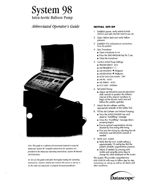
<strong>System</strong><br />
<strong>98</strong><br />
Intia-Aortic Balloon Pump<br />
Abbreviated Operator’s Guide<br />
Note: Dais guide is a reference for personnel trained in using the<br />
<strong>Datascope</strong> <strong>System</strong> <strong>98</strong>. Complete instructions for operation are<br />
provided in the <strong>Datascope</strong> Operating Instructions: <strong>System</strong> <strong>98</strong> <strong>Manual</strong><br />
(00 70-00-0402).<br />
Do not use this guide until after thoroughly reading the Operating<br />
Instructions, Caution: Federal law restricts this device to sale by or<br />
on the order of a physician orproperly licensed practitioner<br />
INITIAL SET-UP<br />
1<br />
2<br />
3<br />
4<br />
5<br />
Confirm Initial Pump Settings:<br />
TRIGGER SELECT : ECG<br />
IAB FREQUENCY 1: 1<br />
IAB INFLATION V Midpoint<br />
IAB DEFLATION V Midpoint<br />
SLOW GAS LOSS ALARM : ON<br />
IAB i=lll - AUTO<br />
IAB TIMING AUTO<br />
ECG GAIN - NORMAL<br />
6. Set initial Timing:<br />
7.<br />
8.<br />
Establish power, verify MAINS POWER<br />
SWITCH and IABP ON/OFF SWITCH are ON<br />
Open Helium tank and verify Helium<br />
pressure<br />
Establish ECG and pressure connections<br />
from the patient<br />
Zero Transducer<br />
Open transducer to air<br />
w Press the ZERO PRESSURE key for 2 sec.<br />
Close the transducer<br />
w Adjust IAB INFLATION and IAB DEFLATION<br />
slide controls to position the inflation<br />
interval of the arterial waveform to<br />
be in at the dicrotic notch and end<br />
be&e the systolic upstroke.<br />
Attach the IAB catheter and the<br />
appropriate extender to the Safety Disk<br />
Fill the IAB Catheter and Initiate Pumping:<br />
Press the ASSIST /STANDBY key and<br />
observe “Autofilling” message<br />
Once the “Autofilling” message clears,<br />
pumping begins<br />
Ensure optimal augmentation during<br />
diastole by fine tuning IAB timing<br />
Fine tune the timing by adjusting the IAB<br />
INFLATION<br />
needed.<br />
and DEFLATION controls if<br />
9 Verify AUG. ALARM:<br />
. Verify that the AUG. ALARM setting is<br />
approximately 10 mmHg less that the<br />
patient’s diastolic augmentation pressure.<br />
. Adjust, if needed, by pressing AUG.<br />
ALARM and using the arrow keys to<br />
change the value displayed on the screen<br />
The <strong>System</strong> <strong>98</strong> provides comprehensive<br />
HELP SCREENS with easy to follow step by step<br />
instructions on set-up as well OS all alarm and<br />
alert conditions.<br />
<strong>Datascope</strong>”
TRIGGER SELECT<br />
Trigger is the signal the <strong>System</strong><br />
<strong>98</strong> uses to identify the beginning of the cardiac<br />
cycle. There are five different trigger selections available.<br />
ECG:<br />
The R wave of the ECG is the trigger event.<br />
Pacer rejection is automatic provided the pacer spikes are enhanced on the <strong>System</strong><br />
screen. ESIS (electrosurgical interference suppression) is automatic in this mode.<br />
When the ECG trigger mode is selected, the ECG gain can be varied using the<br />
AUXILIARY ARROW keys.<br />
The ECG gain can be varied from 0.15 to 3.00, relative to a normal gain of 1.0.<br />
VAR x xxx (xxx being the amount of gain from 0.15 to 3.00) will be displayed in<br />
place of ECG SIZE on the monitor screen when variable ECG gain is used.<br />
Note: ECG is the preferred trigger mode<br />
PRESSURE:<br />
The systolic upstroke of the arterial waveform is the trigger event. In normal operation,<br />
the <strong>System</strong> <strong>98</strong> will automatically adapt the pressure trigger threshold to systolic pulse<br />
height of the arterial pressure waveform. Optionally, a fixed pressure trigger threshold<br />
from 7-30 mmHg can be selected using the AUXILIARY ARROW keys. The pressure trigger<br />
threshold is displayed with the trigger source on the monitor screen and the arterial<br />
waveform is marked to indicate the trigger point. When using pressure trigger, the<br />
balloon must be fully deflated before the upstroke of systole.<br />
Precaution: Pressure triggering is NOT recommended for use with irregular rhythms.<br />
rfa dysrhythmia develops while using pressure trigger, the <strong>System</strong> <strong>98</strong> will<br />
automatically adjust deflation timing early to avoid interfering with systolic ejection.<br />
Do not attempt to adjust the deJation control.<br />
<strong>98</strong>
INTERNAL:<br />
The trigger is an internal signal generator allowing asynchronous assistance.<br />
In normal operation, the rate is fixed at 80 BPM. The internal trigger rate can<br />
also be adjusted from 40 to 120 BPM, in increments of 5<br />
BPM, using the<br />
AUXILIARY ARROW keys.<br />
Note: Should the <strong>System</strong> <strong>98</strong> detect a valid QRS complex while in Internal trigger,<br />
automatic R wave deflation is activated and the message “Ecc Detected” will be<br />
displayed on the monitor screen.<br />
Warning: Never remain in the Internal trigger mode if the patient is<br />
generating a cardiac output.<br />
PACER V/A-V:<br />
The ventricular spike of a ventricular or an atrial-ventricular pacemaker is<br />
the trigger event provided there is a 100% paced rhythm (no demand pacing).<br />
Pacemaker spikes must be enhanced for detection.<br />
Pacer V<br />
Assists 100% ventricular paced rhythms up to a rate of 185 beats per minute.<br />
Pacer A-V<br />
Assists 100% atrial-ventricular paced rhythms provided the A-V interval is<br />
between 80-224 msec. and the pacing rate is less than 125 beats per minute.<br />
PACER A:<br />
The R-wave of the ECG is the trigger event. Atria1 pacer spikes are enhanced<br />
and rejected. Atria1 pacemaker pulse rejection time is expanded in this mode<br />
allowing for rejection of large atria1 pacer tails.<br />
Note: Use only ifatrialpacer spikes are interfering with R wave detection in the<br />
ECG trigger mode. Never use Pacer A trigger in the presence of a ventricular<br />
paced rhythm.<br />
I<br />
<strong>System</strong> <strong>98</strong> Controls
TIMING<br />
Timing refers to the positioning of inflation and deflation points on the arterial<br />
waveform. Inflation should occur at the onset of diastole and deflation should occur<br />
prior to ventricular ejection. On the monitor screen, with the pump in Standby, the<br />
Inflation Marker on the arterial waveform identifies the selected period of balloon<br />
inflation. Vertical timing marks, located below the arterial waveform, are also<br />
available to aid with initial timing.<br />
Inflation Marker<br />
,Dicrotic Notch<br />
AUTO TIMING<br />
With initial set-up, the operator selects the desired inflation and deflation points<br />
while in Standby, utilizing the Inflation Marker on the arterial waveform or the<br />
vertical Inflation Markers located below the arterial waveform. After initiating<br />
assist, the IAB INFLATION and IAB DEFLATION controls can be adjusted to maximize<br />
augmentation and hemodynamic unloading. The <strong>System</strong><br />
<strong>98</strong> will adjust timing<br />
automatically to accommodate changes in the patient’s heart rate and rhythm.<br />
MANUAL TIMING<br />
In manual timing, the operator sets fixed inflation and deflation points as a function<br />
of time relative to the trigger point. If the heart rate varies by more than 10 BPM,<br />
readjustment of timing may be required.<br />
Timing at a frequency of 1:2 is illustrated below:<br />
In both AUTO and MANUAL timing, it is possible to view the inflation period while<br />
assisting, by pressing and holding the INFLATION INTERVAL key. The highlighted<br />
portion indicates the period of balloon inflation. Vertical Inflation Markers located<br />
below the arterial waveform will also be displayed when the INFLATION INTERVAL<br />
key is pressed.
SYSTEM ALARMS, ALERTS, AND STATUS/PROMPTS<br />
The <strong>System</strong><br />
<strong>98</strong> provides the operator with comprehensive HELP SCREENS for<br />
all of the Alarms and Alerts. In the presence of an Alarm or Alert message,<br />
the operator can utilize the HELP SCREEN by pressing the HELP key on the<br />
control panel. The operator will be provided with step by step troubleshooting<br />
instructions. Detailed information on all Alarms, Alerts, and Status/Prompts is<br />
provided in the <strong>System</strong> <strong>98</strong> Operating Instructions.<br />
ALARMS<br />
ALARM messages are displayed in the ALARM MESSAGES section of the monitor<br />
display. IABP assist is suspended and a steady tone will sound.<br />
TRIGGER ALARMS<br />
These alarms indicate the selected trigger source is either not available or<br />
not reliable. Pumping is suspended and a steady tone sounds. Pumping will<br />
automatically resume once the trigger has been reestablished.<br />
MESSAGE CAUSE<br />
,,.....,.,<br />
No Trigger Valid trigger does not exist<br />
No Pressure Trigger Valid trigger does not exist while in Pressure<br />
Trigger<br />
No Pressure Trigger - Pressure Trigger is selected but the transducer has<br />
Zero Transducer not been zeroed<br />
Trigger Interference Electrosurgical interference while in Pacer Trigger<br />
Check Pacer Timing V/A-V Pacer Trigger requirements have not been<br />
met<br />
OPERATOR INTERVENTION<br />
Assess the selected trigger and associated trigger criteria. If necessary, change<br />
trigger selection and resume pumping by pressing the ASSIST/STANDBY key.
CATHETER ALARMS<br />
The <strong>System</strong><br />
<strong>98</strong> continually monitors specific parameters within the closed patient<br />
pneumatic system. If a change is detected or a specific parameter is violated, IABP<br />
assist is suspended and a continuous tone will sound.<br />
MESSAGE CAUSE<br />
Leak in IAB Circuit Small gas loss, gas gain, or slow leak in the<br />
catheter circuit<br />
Rapid Gas Loss Large leak in<br />
IAB Disconnected<br />
Check LAB Catheter<br />
IAB catheter or catheter extender<br />
IAB catheter or catheter extension tubing disconnected<br />
IAB catheter or catheter extender tubing kinked or<br />
balloon not fully unwrapped<br />
Blood Detected Blood has migrated into the drain tubing due to a leak<br />
in the IAB.<br />
Autofill Failure - IAB could not be adequately filled due to an<br />
No Helium inadequate supply of Helium<br />
Autofill Failure IAB could not be automatically filled but Helium<br />
supply is adequate<br />
Autofill Required The <strong>System</strong> <strong>98</strong> has been switched from manual fill<br />
to auto fill or pump was placed in standby<br />
during the two hour scheduled auto fill<br />
OPERATOR INTERVENTION<br />
Inspect the IAB and catheter extender tubing for any evidence of a leak, including<br />
the safety disk/condensate removal assembly connections, IAB catheter connections,<br />
autofill tubing and drain port. Verify all connections are leak free. For “Autofill<br />
Failure-No Helium” open or replace Helium tank if necessary. Inspect the IAB<br />
catheter and catheter extender for evidence of a kink or restriction to Helium flow.<br />
Fill the IAB, if instructed, by pressing the IAB FILL key. Resume pumping by pressing<br />
ASSIST/STANDBY.<br />
Warning: If blood is observed within the catheter or catheter extender tubing at<br />
any time during the IAB procedure, stop pumping and notify the physician<br />
immediately.<br />
Warning: When the <strong>System</strong> is operated in MANUAL FILL, the IAB gas loss and<br />
catheter alarms are disabled. The message, “Gas Loss And Catheter Alarms<br />
Disabled” will be displayed in the Advisory section of the display. The IAB status<br />
bar will not be active.<br />
JAB<br />
.<br />
.<br />
.<br />
Warning: Under certain heart ra<br />
suspended. Refer to the Operat
PNEUMATIC ALARMS<br />
Pressure and vacuum are monitored internally within the system. When the<br />
parameters are violated, pumping is suspended and an audible alarm sounds.<br />
MESSAGE CAUSE<br />
.......... .................... .. .... ....................... ... ... ................... .. ............<br />
High Drive Pressure Regulated drive pressure exceeds acceptable<br />
level<br />
.I.....<br />
Low Vacuum Insufficient or no compressor vacuum<br />
OPERATOR INTERVENTION<br />
Press the ASSIST/STANDBY key to resume pumping. If “Low Vacuum” persists and<br />
the patient is tachycardiac, change IAB FREQUENCY to 1:2. Pumping suspended<br />
due to a Low Vacuum alarm will resume automatically when vacuum is restored.<br />
If either alarm condition persists, contact <strong>Datascope</strong> service.<br />
SYSTEM SURVEILLANCE ALARMS<br />
The <strong>System</strong> <strong>98</strong> provides internal surveillance of certain parameters within the<br />
console.<br />
MESSAGE CAUSE<br />
Electrical Test Fails Electrical failure during power-up diagnostics<br />
Code #<br />
<strong>System</strong> Failure Microprocessor or other electronic/pneumatic<br />
failure<br />
Safety Disk Test Fails Leak in safety disk/condensate removal assembly<br />
or pneumatic fitting during a safety disk leak test<br />
OPERATOR INTERVENTION<br />
Refer to help screens and/or the Operating Instructions.
ALERTS<br />
Alert messages are displayed in the ADVISORY section of the screen.<br />
LtzB pumping is<br />
not suspended with Alert conditions. A double beep tone signals the operator that<br />
corrective action is required. Alert conditions that do not require immediate<br />
intervention will result in a double beep tone that repeats for 30 seconds<br />
(no tone will sound for “Heart Rate Low”). The Alert message remains displayed<br />
until the alert condition is corrected.<br />
..............................................<br />
MESSAGE ....................... .............. ........<br />
CAUSE<br />
Augmentation Below Diastolic augmentation has dropped below limit set<br />
Limit Set<br />
Irregular Trigger Pressure trigger in the presence of irregular rhythms<br />
or with deflation set too late<br />
.<br />
Heart Rate Low Heart rate -40 BPM<br />
Low Helium Helium supply is below<br />
24-811 reserve<br />
Low<br />
.,..<br />
Battery<br />
,.<br />
Battery time is below 30 minutes of operating time<br />
............................................ ................. ................ .. .... .I ......... ...... ..<br />
Low Battery (EXT) External battery time is below 30 minutes of<br />
operating time<br />
ECG Detected<br />
.................. .... .......... ........ .... .....................<br />
ECG activity exists while in Internal Trigger<br />
.................................. .................... ...................................... .................... ............ .......... ...... ................ .......... ....... .... ..... .<br />
Prolonged Time in Standby Pump has been in Standby for at least 20 minutes<br />
Maintenance Required <strong>System</strong> maintenance may be required<br />
.,........<br />
Code #<br />
.,.................,.....,.................,..,. .,......................<br />
No Patient Status Available Internal communications failure<br />
.<br />
........<br />
...... .-
STATUS/PROMPTS<br />
Status/Prompt messages are displayed in the ADVISORY section of the display.<br />
Status/Prompt messages do not sound any tones (with the exception of “Unplug<br />
Disk Outlet”<br />
& “Plug Disk Outlet”) and are advisory in nature.<br />
STATUS MESSAGE CAUSE<br />
<strong>System</strong> Trainer Indicates Series 90 Trainer in use<br />
<strong>System</strong> Test O.K. Power-up diagnostics tests pass<br />
Autofilling<br />
R-Wave Deflate<br />
Leak Testing Safety Disk Indicates safety disk leak test is in<br />
...,...<br />
progress<br />
.................. ............. .... .. ......... ....,.,,., .. .. ..<br />
Slow Gas Loss Override On Operator has disabled the slow gas loss alarm<br />
Gas Loss and Catheter<br />
Alarms Disabled<br />
IAB Not Filled<br />
L4B has not been filled<br />
............ ......................................................................................................<br />
Unplug Disk Outlet Instruction given at the start of a safety disk leak<br />
test<br />
Plug Disk Outlet Instruction given during safety disk leak test<br />
<strong>Manual</strong> Fill IAB Displayed during the manual fill process<br />
AUXILIARY MESSAGE CAUSE<br />
Operator has selected the manual fill mode<br />
Battery in Use Internal battery is being used<br />
Battery in Use (EXT) External battery or DC power source is being used<br />
PROMPT MESSAGE CAUSE<br />
...............................................<br />
.... .................<br />
........ ., ..,..,..,..<br />
Notifies the operator the system is automatically<br />
purging and refilling the L4B<br />
Operator has enabled R-wave deflation by moving<br />
deflation slide control to the extreme right position<br />
Help Displayed on bottom of monitor at power-up until<br />
Available for Initial Set Up first pumping cycle<br />
Help Displayed on bottom of screen when user selects<br />
Available for <strong>Manual</strong> Fill IAB <strong>Manual</strong> Fill Mode<br />
..<br />
..... ,.._.
CLINICAL CONSIDERATIONS, ROUTINE CHECKS,<br />
PORTABLE OPERATION<br />
CLINICAL CONSIDERATIONS<br />
ECG<br />
There are several methods to correct conditions which alter or hamper the<br />
acquisition of a reliable ECG. Repositioning electrodes to the anterior thoracic<br />
chest or replacement of the ECG electrodes, checking that the patient cable is<br />
properly connected, choosing an alternate lead selection and adjusting the ECG Gain<br />
setting are the most common solutions. If the ECG signal is acquired from a bedside<br />
monitor, ensure the appropriate cable is utilized, ECG External is selected using the<br />
PATIENT WAVEFORM ECG<br />
LEAD/EXT. key, and the bedside monitor is in the diagnostic<br />
output mode.<br />
ARRHYTHMIAS<br />
Atria1 Fibrillation - Use AUTO TIMING and ECG TRIGGER.<br />
IAB INFLATION and IAB DEFLATION should be adjusted to position the Inflation<br />
Markers of the arterial waveform to correspond with diastole. Moving the IAB<br />
DEFLATION slide control to the extreme right will result in automatic R wave<br />
deflation. The Status message “R-Wave Deflate” will be displayed in the ADVISORY<br />
section of the monitor. Adjust the augmentation alarm limit using the AUG<br />
ALARM key and the UP and DOWN ARROW keys to accommodate any change in<br />
the patient’s pressure.<br />
Ectopics<br />
The <strong>System</strong> <strong>98</strong> automatically deflates when an ectopic beat is sensed and will<br />
then inflate the IAB during diastole of the ectopic. To ensure reliable triggering<br />
with ectopics, select the lead that minimizes the amplitude differences between<br />
the normal QRS and the ectopic. If the arterial pressure decreases during the<br />
ectopic beat, the diastolic augmentation pressure may also decrease.<br />
Cardiac Arrest/Defibrillation<br />
If possible, use ECG or PRESSURE Trigger during CPR. The system will synchronize<br />
trigger to the rate and rhythm of chest compressions. If ECG or PRESSURE<br />
Trigger cannot be utilized, INTERNAL Trigger may be utilized to allow balloon<br />
movement. When defibrillating, the <strong>System</strong> <strong>98</strong> is completely isolated from the<br />
patient, however, the operator should stand clear of the <strong>System</strong> during defibrillation.<br />
This is especially important during battery (ungrounded) operation.<br />
Note: i%e IAB should not remain immobile for more than 30 minutes in situ.<br />
ARTERIAL PRESSURE DISPLAY<br />
When IAB Frequency is 1:2 or 1:3, the unassisted systolic and diastolic<br />
pressures will be displayed on the monitor immediately below the assisted<br />
systolic and diastolic pressures.
CHANGE IN PRESSURE MONITORING SITE<br />
If the arterial pressure monitoring site is changed while pumping, quickly press<br />
and release the INFLATION INTERVAL key to recalculate arterial pressure<br />
transmission delay. This will ensure accurate digital pressure displays and<br />
appropriate display of the Inflation Markers.<br />
SAFETY DISK LEAK TEST<br />
The Safety Disk should be removed from the condensate removal module and<br />
replaced after 1000 hours of use or 2 years, whichever comes first. The Safety<br />
Disk should also be checked on a regular basis. To initiate the Safety Disk Leak<br />
Test, the following procedure should be performed:<br />
1. Press and hold the IAB FILL key while turning on the power. Release the IAB<br />
FILL key when the message “Leak Testing Safety Disk” is displayed in the<br />
ADVISORY section of the monitor screen.<br />
2. After approximately 10 seconds, a tone will sound and the message “Plug<br />
Disk Outlet” will be displayed adjacent to the ADVISORY section.<br />
3. Plug the<br />
IAB CATHETER EX TENDER INPU T with a luer lock plug or a closed<br />
stopcock.<br />
4. The <strong>System</strong> <strong>98</strong> will proceed with the test which takes approximately<br />
When the test is complete, a 10 second tone will sound and the message<br />
6 minutes.<br />
“<strong>System</strong> Test O.K.” or “Safety Disk Test Fails” is displayed adjacent to the<br />
ADVISORY section.<br />
If the Safety Disk leak test fails, check all pneumatic connections. Turn the<br />
pump OFF and repeat from Step 1. If the Safety Disk Leak Test fails again,<br />
replace the Safety Disk.<br />
Warning: This procedure must not be performed when the system is connected<br />
to the patient.<br />
PC-IABP REMOTE MODEM DIAGNOSTICS<br />
The <strong>System</strong> <strong>98</strong> is equipped with a telephone jack located on the rear panel<br />
below the Helium tank. When a direct dial analog telephone line is connected<br />
from the telephone jack in the wall to the telephone jack in the IABP, patient<br />
data, waveforms, and pump information can be accessed from a remote location<br />
using a computer and the PC-IABP software.<br />
To use the modem capabilities of the <strong>System</strong> <strong>98</strong>:<br />
Connect a telephone cord from the telephone jack in the wall to the port<br />
labeled “Phone Line” on the rear panel of the <strong>System</strong> <strong>98</strong> below the Helium<br />
tank.<br />
From a separate telephone line, contact the person who is going to connect<br />
by computer with the IABP and provide them with the phone number of the<br />
telephone line connected to the IABP.<br />
They can now connect with the IABP to view waveforms, patient data, and<br />
pump information.
STRIP CHART RECORDER<br />
The dual trace recorder provides a hard copy record of ECG and arterial pressure, ECG<br />
and balloon pressure waveform, or arterial pressure and balloon pressure waveform.<br />
Alarm/ Advisory messages, Timing and Trigger mode, heart rate and arterial pressures<br />
are provided at the end of the strip. Trigger event markers are annotated across the top<br />
of the strip with an inflation marker at the bottom of the strip. To activate the recorder,<br />
press the<br />
PRINT STRIP key. To end the recording, press the PRINT STRIP key again.<br />
Trend data can also be printed from the recorder using the Printer Menu.<br />
A Printer Menu allows the user to configure the printer for specific functions.<br />
Press the PRINTER MENU key to access the printer configuration menu. Use the UP and<br />
DOWN ARROW keys to highlight a menu item and press the SELECT/CHANGE key to<br />
select specific options for the function. When finished, press DONE to save changes.<br />
PREFERENCES MENU<br />
The preferences menu allows the operator to adjust Audio Preferences, Display<br />
Preferences, or to Set Time and Date.<br />
Press the P REFERENCES MENU key to access the preferences menu. Use the UP and<br />
DOWN ARROW keys to highlight a menu item. Press the SELECT/CHANGE key to select<br />
a menu item or to change a preference item. Press DONE to exit the Preferences<br />
Menu and save changes.<br />
DOPPLER<br />
The <strong>System</strong> <strong>98</strong> is equipped with a doppler located in the upper storage compartment<br />
on the side of the <strong>System</strong> <strong>98</strong> cart.<br />
To Use:<br />
1. After removing the doppler from the storage compartment, press the on/off key<br />
located on the front of the doppler, The LCD will display the power ON indicator.<br />
2. Place a small amount of coupling gel on the doppler probe or at the site to be<br />
examined.<br />
3. Place the probe at a 45 degree angle over the artery to be assessed.<br />
4. Listen for pulsatile blood flow sounds, adjust volume control as needed.<br />
,If battery replacement is necessary, remove the cover of the battery compartment,<br />
and lift out the old battery. Install a new 6LR61, 6LF22, or equivalent 9V alkaline<br />
battery. Slide the cover back into position.<br />
TRANSPORT CONSIDERATIONS<br />
If it is necessary to disconnect patient connections or to detach the battery from the<br />
console to facilitate movement into a transport vehicle or aircraft, the <strong>System</strong> <strong>98</strong><br />
will hold pump settings in memory for 15 minutes. Once the patient and pump are<br />
reattached, turn the power ON, verify timing settings, press ASSIST/STANDBY to Auto<br />
Fill the IAB and resume pumping.
PORTABLE OPERATION<br />
Portable Operation from Internal Batteries:<br />
To switch from AC power to battery operation, unplug the power cord from<br />
the AC outlet. The <strong>System</strong><br />
<strong>98</strong> switches automatically to portable operation. The<br />
batteries recharge whenever the <strong>System</strong> <strong>98</strong> is plugged into an AC outlet with the<br />
MAINS switch ON. To maintain batteries at full charge and maximize battery life, it<br />
is recommended that the <strong>System</strong> be plugged in at all times even when not in use.<br />
The message, “Battery In Use,” will be displayed in the ADVISORY section of the<br />
monitor and the BATTERY INDICATOR will be display on the monitor screen whenever<br />
the <strong>System</strong> is operated from the internal batteries. When approximately 30<br />
minutes of battery operation time remains, the following occurs: The message,<br />
“Low Battery,” is continuously displayed in the ADVISORY section and a double<br />
beep alarm is activated for 30 seconds.<br />
To return to AC power, plug the AC power cord into an AC outlet. The <strong>System</strong><br />
automatically switches to AC operation and the internal batteries will recharge.<br />
Verify BAITERY CHARGING LED is either continuously illuminated or is flashing<br />
when the system is plugged in.<br />
If the unit is stored for an extended period and AC power is unavailable,<br />
disconnect the system battery pack from the console. Refer to the Operating<br />
Instructions for additional detail.<br />
Portable Operation from Vehicle Inverter:<br />
AC power for the <strong>System</strong> <strong>98</strong> can be supplied from an emergency vehicle inverter.<br />
The inverter should be checked for proper operation. Refer to the Operating<br />
Instructions for vehicle inverter specifications. Interruption of the vehicle inverter<br />
AC power will result in portable internal battery operation.<br />
Portable Operation-External DC Source:<br />
The <strong>System</strong> <strong>98</strong> can also be powered from a voltage compatible external 24 volt<br />
DC power source. The message, “Battery in Use (EXT)” will be displayed in the<br />
ADVISORY section of the monitor when the <strong>System</strong> <strong>98</strong> is operated from the<br />
external DC power source. Interruption of the external DC source will result in<br />
portable internal battery operation. Refer to the Operating Instructions for<br />
additional detail.<br />
ALTITUDE CHANGES DURING AIR TRANSPORT<br />
For proper operation during air transport, the <strong>System</strong> <strong>98</strong> balloon pressure<br />
must adapt to local atmospheric pressure. In the Auto Fill mode, the system<br />
will automatically purge and fill the IAB when local atmospheric pressure<br />
decreases or increases by 25 or 50 mmHg respectively. These pressure changes<br />
occur approximately every 1,000 feet of rise or 2,000 feet of drop in altitude.<br />
The Auto Fill mode should be used during air transport. If the Auto Fill mode<br />
cannot be used and the <strong>Manual</strong> Fill mode is required, a <strong>Manual</strong> Fill must be<br />
performed at the same intervals that an Auto Fill would occur.
REMOVING PUMP CONSOLE FROM THE CART<br />
The console can be removed from the cart with or without the battery pack attached.<br />
When removing the pump console or the monitor from the cart or returning them to<br />
the cart, ensure that the wheels of the cart are in the locked position. Push the<br />
handle swivel release down (Fig. 1) and turn the cart handle counter-clockwise.<br />
fig. 1<br />
To remove the console with the battery pack attached:<br />
Unlock the console by pressing the tab to the right of the console release handle<br />
and pull the handle straight out (Fig. 2). Lift the pump console straight up and<br />
off the cart.
To remove the console by detaching the battery pack:<br />
With the console on the cart, lift the battery release levers to the unlock<br />
position (Fig. 3). Lift the console straight up and off the cart. To release the<br />
battery from the cart, unlock the battery pack by pressing the tab to the right<br />
of the console release handle and pull the release handle straight out. Lift the<br />
battery pack off the cart. With the release levers in the unlocked position, lift<br />
the pump console and lower it straight down onto the battery pack. Return the<br />
release levers to the locked position (Fig 4).<br />
Pump<br />
-<br />
Release Levers<br />
,J
To attach the monitor to the pump console:<br />
Detach the monitor from the cart handle by pressing the button on the rear of the<br />
monitor (Fig. 5). Attach the monitor to the top of the pump console. Make sure the<br />
monitor is securely attached before moving the system. Extend the console handle<br />
until it locks into position, tilt the <strong>System</strong>, and pull to transport. (Fig. 6.)<br />
<strong>Datascope</strong> Corp.<br />
Cardiac Assist Division<br />
15 Law Drive<br />
Fairfield, NJ 07004<br />
U.S.A.<br />
For Emergency Assistance:<br />
1.800.777.4222 (within the U.S.)<br />
1.973.244.6100 (outside the U.S.)<br />
<strong>Datascope</strong>”