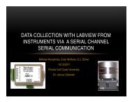
General Purpose Interface Bus in Data Acquisition and Control
General Purpose Interface Bus in Data Acquisition and Control
General Purpose Interface Bus in Data Acquisition and Control

You also want an ePaper? Increase the reach of your titles
YUMPU automatically turns print PDFs into web optimized ePapers that Google loves.
y<br />
Santiago Salazar<br />
Chris Paul<strong>in</strong>o<br />
12/15/11<br />
Florida Gulf Coast University<br />
Dr. Zalewski
Previous project by Olexiy Kovtunenko <strong>and</strong> Robert Porter.<br />
They Created a LabView Program to communicate with 2 GPIB devices.<br />
The devices are a HP 34401A multimeter which gets voltage measurements , <strong>and</strong> a<br />
HP 53131A Universal Counter which counts the measurements per second.<br />
We planned to connect another GPIB device to the other two <strong>and</strong> have it<br />
communicate with the LabView program. The device is a HP 33120A Function /<br />
Arbitrary Waveform Generator. It generates waves with changeable sett<strong>in</strong>gs<br />
HP 34401A multimeter HP 53131A Universal Counter HP 33120A Function /<br />
Arbitrary Waveform Generator
The waveform generator <strong>and</strong> the other GPIB devices are connected to the<br />
computer with GPIB cables.<br />
The GPIB cables are connected <strong>in</strong> serial fashion<br />
The cables on the multimeter <strong>and</strong> waveform generator are both connected<br />
to the cable on the counter.<br />
The cable on the counter is connected to the computer<br />
This allows them all to communicate with the computer
We used a BNC cable to connect the counter <strong>and</strong> the multimeter to the<br />
waveform generator. One BNC cable is connected from Channel 1 on the<br />
counter to Sync on the waveform generator.<br />
Instead of an ord<strong>in</strong>ary BNC cable, the multimeter needed a BNC to<br />
Regular Battery cable. The BNC part is connected to “Output” on the<br />
waveform generator. The positive <strong>and</strong> negative battery connections are<br />
connected to the <strong>in</strong>put on the multimeter.
The LabView program communicates with the GPIB devices by us<strong>in</strong>g str<strong>in</strong>g<br />
comm<strong>and</strong>s.<br />
An example of a comm<strong>and</strong> that can be sent to the waveform generator to control<br />
its sett<strong>in</strong>gs:<br />
APPL:SIN 0.1 HZ, 1.0 VPP, 0 V<br />
Creates a s<strong>in</strong>e wave at a frequency of 0.1 Hz, 1.00 VPP amplitude <strong>and</strong> a offset of 0 V.<br />
The wave, frequency, amplitude <strong>and</strong> offset can all be changed around.<br />
“READ?” is a comm<strong>and</strong> sent from the program to the counter <strong>and</strong> the multimeter<br />
to read the data each device is outputt<strong>in</strong>g.
The front panel of our LabView Program is shown below<br />
It displays a graph of the specified wave at the specified frequency which measures<br />
voltage aga<strong>in</strong>st time.<br />
The Sample # text box reads from the counter <strong>and</strong> displays the number of<br />
measurements taken.<br />
Multimeter <strong>Data</strong> <strong>and</strong> Counter <strong>Data</strong> text boxes display the what is be<strong>in</strong>g outputted<br />
from each respective device. Only voltage can be used for the multimeter <strong>and</strong> we<br />
chose to use frequency for the counter. Either dc or ac voltage measur<strong>in</strong>g can be<br />
selected from the radio buttons<br />
The address boxes are for the user to enter the address of each device so that the<br />
program can communicate with the devices.<br />
The program can be started <strong>and</strong> stopped on the front panel via buttons.
The block diagram of our LabView Program is shown below<br />
Ma<strong>in</strong>ly, it consists of a ma<strong>in</strong> while loop, which conta<strong>in</strong>s comm<strong>and</strong>s that ask the<br />
devices to send data measurements back to the PC<br />
Each iteration of the ma<strong>in</strong> while loop sends a s<strong>in</strong>gle data measurement from both the<br />
multimeter <strong>and</strong> the counter back to the PC<br />
It also <strong>in</strong>volves case structure used to select which type of voltage is to be read<br />
An event case structure sends comm<strong>and</strong>s to the waveform generator whenever the<br />
user click on the appropriate button<br />
Buttons are used to break the while loops<br />
When the ma<strong>in</strong> while loop is broken, the program stops runn<strong>in</strong>g
We <strong>in</strong>corporated the ability to use generated waveforms. By us<strong>in</strong>g a BNC<br />
to regular battery cable to connect the multimeter with the waveform<br />
generator<br />
We added a Universal Counter to the other two GPIB devices <strong>and</strong><br />
connected it to the waveform Generator with a regular BNC cable.<br />
However it only reads accurate data at frequencies of 10 Hz <strong>and</strong> above
We created a new LabView program that would work properly with the<br />
Universal Counter<br />
We added a textbox to display the output of the counter<br />
We added a textbox to display the number of measurements taken<br />
We added textboxes for the address<strong>in</strong>g of each GPIB device so that the<br />
user may change the address if necessary<br />
We added the ability to set the parameters of the waveform generator<br />
from the LabView program itself
We started the project not know<strong>in</strong>g how to <strong>in</strong>terconnect the GPIB<br />
devices<br />
Another complication we encountered was how to send<br />
comm<strong>and</strong>s to the Waveform Generator<br />
The Universal Counter presented some technical problems as we<br />
found out it could only read 10 Hz <strong>and</strong> above when our project<br />
required much less than that<br />
We did research us<strong>in</strong>g the manuals of each device to figure out<br />
how to connect them <strong>and</strong> send comm<strong>and</strong>s to them<br />
Our project works almost exactly the way we want it to. The only<br />
problem is read<strong>in</strong>g low frequencies from the counter as mentioned<br />
above