AVT*VG, AVT/VGF (PN 25) - Danfoss.com
AVT*VG, AVT/VGF (PN 25) - Danfoss.com
AVT*VG, AVT/VGF (PN 25) - Danfoss.com

You also want an ePaper? Increase the reach of your titles
YUMPU automatically turns print PDFs into web optimized ePapers that Google loves.
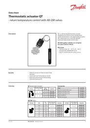
Data sheet<br />
Temperature controller (<strong>PN</strong> <strong>25</strong>)<br />
<strong>AVT</strong> / VG - external thread<br />
<strong>AVT</strong> / <strong>VGF</strong> - flange<br />
Description<br />
Ordering<br />
Example:<br />
Temperature controller, DN 15,<br />
k vs 1.6, <strong>PN</strong> <strong>25</strong>, setting range 40 - 90 °C,<br />
t max 150 °C, ext. thread<br />
- 1x VG DN 15 valve<br />
Code No: 065B0772<br />
- 1x <strong>AVT</strong> thermostat, 40 - 90 °C<br />
Code No: 065-0598<br />
Option:<br />
- 1x Weld-on tailpieces<br />
Code No: 003H6908<br />
VG, <strong>VGF</strong> valve<br />
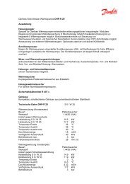
Picture<br />
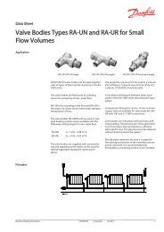
<strong>AVT</strong> / VG<br />
<strong>AVT</strong> / <strong>VGF</strong><br />
The <strong>AVT</strong> / VG(F) controller is a self-acting<br />
proportional temperature controller developed<br />
primarily for domestic hot water (DHW)<br />
production:<br />
- Hot water tanks<br />
- Storage charge systems<br />
- Instantaneous domestic hot water production<br />
It can be used in mixing loops and room heating<br />
systems as well. Controller closes on rising<br />
temperature.<br />
The temperature controller is type-tested<br />
according to EN 14597 and can be used in<br />
<strong>com</strong>binations with safety temperature monitors<br />
STM and safety temperature limiters STL.<br />
Flow and return mounting.<br />
Main data:<br />
• DN 15 - 50<br />
• k vs 0.4 - <strong>25</strong> m 3 /h<br />
• <strong>PN</strong> <strong>25</strong><br />
• Setting ranges:<br />
-10 … 40 °C / 20 … 70 °C / 40 … 90 °C / 60 … 110 °C<br />
and<br />
10 … 45 °C / 35 … 70 °C / 60 … 100 °C / 85 … 1<strong>25</strong> °C<br />
• Temperature:<br />
- Circ. water / glycolic water up to 30%:<br />
2 … 150 °C<br />
• Connections:<br />
- Ext. thread (weld-on, thread and flange<br />
tailpieces)<br />
- Flange<br />
DN<br />
(mm)<br />
kvs (m<br />
<strong>PN</strong><br />
tmax. Connection Code No.<br />
3/h) (°C)<br />
0.4<br />
065B0770<br />
1.0 065B0771<br />
15 1.6 G ¾ A 065B0772<br />
2.5 065B0773<br />
20<br />
4.0<br />
6.3<br />
Cylindrical external<br />
thread acc. to<br />
ISO 228/1<br />
G 1 A<br />
065B0774<br />
065B0775<br />
<strong>25</strong> 8.0 G 1¼ A 065B0776<br />
32<br />
40<br />
12.5<br />
16<br />
<strong>25</strong> 150<br />
G 1¾ A<br />
G 2 A<br />
065B0777<br />
065B0778<br />
50 20 G 2½ A 065B0779<br />
15 4.0<br />
065B0780<br />
20 6.3 065B0781<br />
<strong>25</strong><br />
32<br />
8.0<br />
12.5<br />
Flanges <strong>PN</strong> <strong>25</strong>, acc. to EN 1092-2<br />
065B0782<br />
065B0783<br />
40 20 065B0784<br />
50 <strong>25</strong> 065B0785<br />
DH-SMT/SI VD.JK.A2.02 © <strong>Danfoss</strong> 02/2011 1
Data sheet Temperature controller <strong>AVT</strong> / VG(F) (<strong>PN</strong> <strong>25</strong>)<br />
Ordering (continuous)<br />
<strong>AVT</strong> thermostat<br />
Picture For valves Setting range<br />
Temperature sensor with brass<br />
immersion pocket, length,<br />
connection<br />
Code No.<br />
-10 … +40 °C<br />
DN 15 - <strong>25</strong><br />
170 mm, R ½” 1)<br />
065-0596<br />
20 … 70 °C<br />
40 … 90 °C<br />
065-0597<br />
065-0598<br />
60 … 110 °C 065-0599<br />
-10 … +40 °C<br />
DN 32 - 50<br />
210 mm, R ¾” 1)<br />
065-0600<br />
20 … 70 °C<br />
40 … 90 °C<br />
065-0601<br />
065-0602<br />
60 … 110 °C 065-0603<br />
10 … 45 °C<br />
065-0604<br />
DN 15 - 50<br />
35 … 70 °C<br />
60 … 100 °C<br />
<strong>25</strong>5 mm, R ¾” 1) 2)<br />
065-0605<br />
065-0606<br />
85 … 1<strong>25</strong> °C 065-0607<br />
1) conic male thread EN 10226<br />
2) without immersion pocket<br />
Accessories for valves<br />
Picture Type designation DN Connection Code No.<br />
15<br />
003H6908<br />
20 003H6909<br />
Weld-on tailpieces<br />
<strong>25</strong><br />
32<br />
-<br />
003H6910<br />
003H6911<br />
40 003H6912<br />
50 003H6913<br />
15<br />
R ½” 003H6902<br />
External thread tailpieces<br />
20<br />
<strong>25</strong><br />
Conical ext. thread acc. to<br />
EN 10226-1<br />
R ¾”<br />
R 1”<br />
003H6903<br />
003H6904<br />
32 R 1¼” 003H6905<br />
15<br />
003H6915<br />
Flange tailpieces<br />
20 Flanges <strong>PN</strong> <strong>25</strong>, acc. to EN 1092-2 003H6916<br />
<strong>25</strong> 003H6917<br />
Accessories for thermostats<br />
Picture Type designation For valves Material Code No.<br />
Immersion pocket<br />
DN 15 - <strong>25</strong><br />
DN 32 - 50<br />
Brass<br />
Stainless steel, mat. No. 1.4571<br />
Brass<br />
Stainless steel, mat. No. 1.4435<br />
065-4414*<br />
065-4415*<br />
065-4416*<br />
065-4417*<br />
Combination piece K2 003H6855<br />
Combination piece K3 003H6856<br />
* Not for <strong>AVT</strong> thermostat code numbers: 065-0604, 065-0605, 065-0606, 065-0607<br />
Service kits<br />
Picture Type designation DN (mm) kvs (m3 /h) Code No.<br />
0.4 003H6869<br />
1.0 003H6870<br />
15<br />
1.6 003H6871<br />
Valve insert<br />
2.5<br />
4.0<br />
003H6872<br />
003H6873<br />
20 6.3 003H6874<br />
<strong>25</strong> 8.0 003H6875<br />
32 / 40 / 50 12.5 / 16 / 20 / <strong>25</strong><br />
for sensors<br />
003H6876<br />
Sensor stuffing box set<br />
<strong>AVT</strong> R ½” 065-4420<br />
<strong>AVT</strong> R ¾” 065-4421<br />
2 VD.JK.A2.02 © <strong>Danfoss</strong> 02/2011 DH-SMT/SI
Data sheet Temperature controller <strong>AVT</strong> / VG(F) (<strong>PN</strong> <strong>25</strong>)<br />
Technical data<br />
Application principles<br />
Valves<br />
Nominal diameter DN 15 20 <strong>25</strong> 32 40 50<br />
kvs value m3 /h 0.4 1.0 1.6 2.5 4.0 6.3 8 12.5 16/201) 20/<strong>25</strong>1) Cavitation factor z * ≥ 0.6<br />
Leakage acc. to standard IEC 534 0.02 0.05<br />
Nominal pressure <strong>PN</strong> <strong>25</strong><br />
Max. differential pressure bar 20 16<br />
Medium Circulation water / glycolic water up to 30%<br />
Medium pH Min. 7, max. 10<br />
Medium temperature 2 … 150 ° C<br />
valve Thread and flange<br />
Connections<br />
Materials<br />
tailpieces<br />
Weld-on and flange<br />
External thread<br />
Weld-on<br />
-<br />
Ductile iron<br />
Valve body<br />
thread Red bronze CuSn5ZnPb (Rg5)<br />
EN-GJS-400-18-LT<br />
(GGG 40.3)<br />
flange Ductile iron EN-GJS-400-18-LT (GGG 40.3)<br />
Valve seat Stainless steel, mat. No. 1.4571<br />
Valve cone Dezincing free brass CuZn36Pb2As<br />
Sealing EPDM<br />
* k v /k vs ≤ 0.5 at DN <strong>25</strong> and higher<br />
1) Flange valve body<br />
Thermostat<br />
Setting range X s<br />
DH-SMT/SI VD.JK.A2.02 © <strong>Danfoss</strong> 02/2011 3<br />
°C<br />
-10 … 40 °C / 20 … 70 °C / 40 … 90 °C / 60 … 110 °C<br />
10 … 45 °C / 35 … 70 °C / 60 … 100 °C / 85 … 1<strong>25</strong> °C<br />
Time constant T acc. to EN 14597 s max. 50 (170 mm, 210 mm), max. 30 (<strong>25</strong>5 mm)<br />
Gain K s mm/°K 0.2 (170 mm), 0.3 (210 mm), 0.7 (<strong>25</strong>5 mm)<br />
Max. adm. temperature at sensor 50 °C above maximum setpoint<br />
Perm. amb. temperature at sensor 0 … 70 °C<br />
Nominal pressure sensor <strong>PN</strong> <strong>25</strong><br />
Capillary tube length 5 m (170 mm, 210 mm), 4 m (<strong>25</strong>5 mm)<br />
Material<br />
Temperature sensor Cooper / Brass<br />
Immersion pocket *<br />
Ms design<br />
Stainless steel design<br />
Brass, nickel-plated<br />
Mat. No. 1.4571 (170 mm), mat. No. 1.4435 (210 mm)<br />
Handle for temp. setting Polyamide, glass fiber-reinforced<br />
Scale carrier Polyamide<br />
* for sensor 170 and 210 mm
Data sheet Temperature controller <strong>AVT</strong> / VG(F) (<strong>PN</strong> <strong>25</strong>)<br />
Combinations<br />
Example:<br />
Temperature controller with safety<br />
temperature monitor, DN 15, k vs 1.6,<br />
<strong>PN</strong> <strong>25</strong>, setting range 40 - 90 °C,<br />
t max 150 °C, ext. thread<br />
- 1x VG DN 15 valve<br />
Code No: 065B0772<br />
- 1x <strong>AVT</strong> thermostat, 40 - 90 °C<br />
Code No: 065-0598<br />
- 1x STM thermostat, 30 - 110 °C<br />
Code No: 065-0608<br />
- 1x K2 <strong>com</strong>bination piece<br />
Code No: 003H6855<br />
Note:<br />
For safety temperature monitor<br />
STM / VG(F) and safety temperature<br />
limiter STLV see relevant data sheet.<br />
Installation positions<br />
<strong>AVT</strong> / <strong>AVT</strong> / VG<br />
- two temperature controllers<br />
STM / <strong>AVT</strong> / VG<br />
- temperature controller with<br />
safety temperature monitor<br />
STLV / <strong>AVT</strong><br />
- temperature controller with safety<br />
temperature limiter<br />
Temperature controller<br />
Temperature controller <strong>AVT</strong> / VG(F) can be<br />
installed in any position.<br />
STM / <strong>AVT</strong> / <strong>AVT</strong> /VG<br />
- two temperature controllers with<br />
safety temperature monitor<br />
STLV / <strong>AVT</strong> / <strong>AVT</strong><br />
- two temperature controllers with<br />
safety temperature limiter<br />
4 VD.JK.A2.02 © <strong>Danfoss</strong> 02/2011 DH-SMT/SI
Data sheet Temperature controller <strong>AVT</strong> / VG(F) (<strong>PN</strong> <strong>25</strong>)<br />
Installation positions<br />
(continuous)<br />
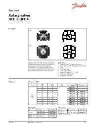
Pressure temperature<br />
diagram<br />
Temperature sensor<br />
The place of installation must be chosen in a way<br />
that the temperature of the medium is directly<br />
taken without any delay. Avoid overheating of<br />
temperature sensor. The temperature sensor<br />
must be immersed into the medium in its full<br />
length.<br />
Temperature sensors 170 mm R½” and 210 mm R¾”<br />
- The temperature sensor may be installed in<br />
any position.<br />
working area<br />
Temperature sensor <strong>25</strong>5 mm R¾”<br />
- The temperature sensor must be installed as<br />
shown on the picture.<br />
EN-GJS-400-18-LT (GGG 40.3) <strong>PN</strong> <strong>25</strong><br />
CuSn5ZnPb (Rg5) <strong>PN</strong> <strong>25</strong><br />
Maximum allowed operating pressure as a function of medium temperature (according to EN 1092-2 and EN 1092-3).<br />
DH-SMT/SI VD.JK.A2.02 © <strong>Danfoss</strong> 02/2011 5
Data sheet Temperature controller <strong>AVT</strong> / VG(F) (<strong>PN</strong> <strong>25</strong>)<br />
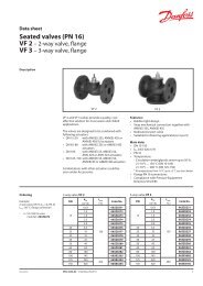
Valve sizing<br />
Given data:<br />
P max = 14 kW<br />
∆t = 20 K<br />
∆p v = 0.15 bar<br />
P max - heating power (kW)<br />
∆t -temperature difference (K)<br />
∆p v - differential pressure across the valve<br />
Maximum flow Q max (m 3 /h) through the valve is<br />
calculated according to formula:<br />
Pmax<br />
× 0.<br />
86 14×<br />
0.<br />
86<br />
Qmax<br />
= =<br />
∆t<br />
20<br />
Q max = 0.6 m 3 /h<br />
k v value is calculated according to formula:<br />
Q<br />
k max<br />
v = =<br />
∆pV<br />
k v = 1.5 m 3 /h<br />
6 VD.JK.A2.02 © <strong>Danfoss</strong> 02/2011 DH-SMT/SI<br />
0.<br />
6<br />
0.<br />
15<br />
Chosen k vs = 1.6 m 3 /h<br />
or read from the sizing diagram by taking a<br />
line through Q scale (0.6 m 3 /h) and ∆p v scale<br />
(0.15 bar) to intersect k v-scale at 1.5 m 3 /h<br />
Chosen k vs = 1.6 m 3 /h<br />
Solution:<br />
The example selects<br />
1) ext. thread valve VG DN 15, k vs value 1.6 or<br />
2) flange valve <strong>VGF</strong> DN 15, k vs value 1.6
Data sheet Temperature controller <strong>AVT</strong> / VG(F) (<strong>PN</strong> <strong>25</strong>)<br />
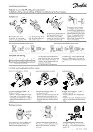
Design<br />
1. Valve VG(F)<br />
2. Valve insert<br />
3. Pressure relieved valve cone<br />
4. Valve stem<br />
5. Union nut<br />
6. Thermostat <strong>AVT</strong><br />
7. Thermostat stem<br />
8. Bellows<br />
9. Setting spring for<br />
temperature control<br />
10. Handle for temperature<br />
setting, prepared for sealing<br />
11. Scale carrier<br />
12. Capillary tube<br />
13. Flexible protected pipe<br />
(only at <strong>AVT</strong> <strong>25</strong>5 mm)<br />
14. Temperature sensor<br />
15. Immersion pocket<br />
Function<br />
Settings<br />
Dimensions<br />
Medium temperature changes cause pressure<br />
changes in temperature sensor. Resulting<br />
pressure is being transferred through the<br />
capillary tube to the bellows. Bellows moves<br />
thermostat stem and opens or closes valve cone.<br />
Temperature setting<br />
Temperature setting is being done by<br />
the adjustment of the setting spring for<br />
temperatature control.<br />
DN 15 20 <strong>25</strong> 32 40 50<br />
SW<br />
32 (G ¾A) 41 (G 1A) 50 (G 1¼A) 63 (G 1¾A) 70 (G 2A) 82 (G 2½A)<br />
d 21 26 33 42 47 60<br />
R<br />
mm<br />
1) ½ ¾ 1 1 ¼ - -<br />
L12) 130 150 160 - - -<br />
L2 131 144 160 177 - -<br />
L3 139 154 159 184 204 234<br />
k 65 75 85 100 110 1<strong>25</strong><br />
d2 14 14 14 18 18 18<br />
n 4 4 4 4 4 4<br />
1) Conical ext. thread acc. to EN 10226-1<br />
2) Flanges <strong>PN</strong> <strong>25</strong>, acc. to EN 1092-2<br />
By increasing of medium temperature valve<br />
cone moves towards the seat (valve closes), by<br />
decreasing of medium temperature valve cone<br />
moves away from the seat (valve opens).<br />
Handle for temperature setting can be sealed.<br />
DH-SMT/SI VD.JK.A2.02 © <strong>Danfoss</strong> 02/2011 7<br />
13
Data sheet Temperature controller <strong>AVT</strong> / VG(F) (<strong>PN</strong> <strong>25</strong>)<br />
Dimensions (continuous)<br />
8 VD.JK.A2.02<br />
DN 15 20 <strong>25</strong> 32 40 50<br />
L<br />
65 70 75 100 110 130<br />
L1 130 150 160 180 200 230<br />
H 180 180 180 221 221 221<br />
mm<br />
H1 229 229 229 221 221 221<br />
H2 34 34 37 62 62 62<br />
H3 47 52 57 70 75 82<br />
Weight<br />
(valves)<br />
Weight<br />
(thermostat)<br />
thread 0.7 0.8 0.9 3.0 3.1 3.8<br />
flange 3.3 4.1 4.7 7.5 9.0 11.1<br />
sensor 170 mm 1.3 kg<br />
sensor 210 mm 1.5 kg<br />
sensor <strong>25</strong>5 mm 1.6 kg<br />
Note: other flange dimensions - see table for tailpieces<br />
Produced by <strong>Danfoss</strong> A/S © 02/2011