Smart-UPS RT 1500/2000 UPS Users Manual - APC Media
Smart-UPS RT 1500/2000 UPS Users Manual - APC Media
Smart-UPS RT 1500/2000 UPS Users Manual - APC Media

Create successful ePaper yourself
Turn your PDF publications into a flip-book with our unique Google optimized e-Paper software.
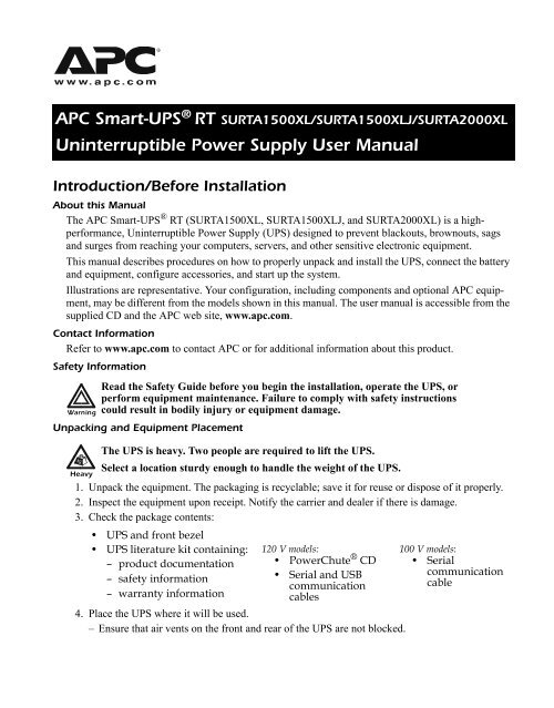
<strong>APC</strong> <strong>Smart</strong>-<strong>UPS</strong> ® <strong>RT</strong> SU<strong>RT</strong>A<strong>1500</strong>XL/SU<strong>RT</strong>A<strong>1500</strong>XLJ/SU<strong>RT</strong>A<strong>2000</strong>XL<br />
Uninterruptible Power Supply User <strong>Manual</strong><br />
Introduction/Before Installation<br />
About this <strong>Manual</strong><br />
The <strong>APC</strong> <strong>Smart</strong>-<strong>UPS</strong> ® <strong>RT</strong> (SU<strong>RT</strong>A<strong>1500</strong>XL, SU<strong>RT</strong>A<strong>1500</strong>XLJ, and SU<strong>RT</strong>A<strong>2000</strong>XL) is a highperformance,<br />
Uninterruptible Power Supply (<strong>UPS</strong>) designed to prevent blackouts, brownouts, sags<br />
and surges from reaching your computers, servers, and other sensitive electronic equipment.<br />
This manual describes procedures on how to properly unpack and install the <strong>UPS</strong>, connect the battery<br />
and equipment, configure accessories, and start up the system.<br />
Illustrations are representative. Your configuration, including components and optional <strong>APC</strong> equipment,<br />
may be different from the models shown in this manual. The user manual is accessible from the<br />
supplied CD and the <strong>APC</strong> web site, www.apc.com.<br />
Contact Information<br />
Refer to www.apc.com to contact <strong>APC</strong> or for additional information about this product.<br />
Safety Information<br />
Warning<br />
Unpacking and Equipment Placement<br />
Heavy<br />
Read the Safety Guide before you begin the installation, operate the <strong>UPS</strong>, or<br />
perform equipment maintenance. Failure to comply with safety instructions<br />
could result in bodily injury or equipment damage.<br />
The <strong>UPS</strong> is heavy. Two people are required to lift the <strong>UPS</strong>.<br />
Select a location sturdy enough to handle the weight of the <strong>UPS</strong>.<br />
1. Unpack the equipment. The packaging is recyclable; save it for reuse or dispose of it properly.<br />
2. Inspect the equipment upon receipt. Notify the carrier and dealer if there is damage.<br />
3. Check the package contents:<br />
• <strong>UPS</strong> and front bezel<br />
• <strong>UPS</strong> literature kit containing:<br />
– product documentation<br />
– safety information<br />
– warranty information<br />
120 V models:<br />
• PowerChute ® CD<br />
• Serial and USB<br />
communication<br />
cables<br />
4. Place the <strong>UPS</strong> where it will be used.<br />
– Ensure that air vents on the front and rear of the <strong>UPS</strong> are not blocked.<br />
100 V models:<br />
• Serial<br />
communication<br />
cable
Installation<br />
– Do not operate the <strong>UPS</strong> where there is excessive dust or the temperature or humidity are<br />
outside the specified limits.<br />
Installation<br />
Refer to instructions below for information on how to install the <strong>UPS</strong> in a rack, as a tower configuration,<br />
or when installing the <strong>UPS</strong> with optional battery pack(s). Once the <strong>UPS</strong> has been placed in the<br />
desired tower or rack location, complete the remaining installation steps in sequential order, beginning<br />
with “Connect Equipment to the <strong>UPS</strong>” on page 2.<br />
To Install the <strong>UPS</strong> in a Rack<br />
See the installation sheet supplied with the optional rail kit (SU<strong>RT</strong>RK) to install the <strong>UPS</strong> in the rack. It<br />
is recommended that you remove the battery before attempting to install it in the rack. See “Battery<br />
Replacement Instructions” on page 11 for the procedure.<br />
To Install the <strong>UPS</strong> as a Tower Configuration<br />
Caution<br />
To Install the <strong>UPS</strong> with External Battery Pack(s)<br />
In addition to the <strong>UPS</strong>, if your configuration includes optional <strong>Smart</strong>-<strong>UPS</strong> <strong>RT</strong> battery pack(s)<br />
(SU<strong>RT</strong>A48XLBP or SU<strong>RT</strong>A48XLBPJ), see the battery pack user manual to complete the physical<br />
installation for the <strong>UPS</strong> with external battery pack(s).<br />
The <strong>UPS</strong> must be installed above external battery pack(s) when in a rack. When installing the <strong>UPS</strong> as<br />
a tower configuration, battery pack(s) must be installed to the right of the <strong>UPS</strong> when facing the front<br />
of the <strong>UPS</strong>. Failure to follow these instructions could result in cabling shortage.<br />
Connect Equipment to the <strong>UPS</strong><br />
Caution<br />
2.5<br />
cm<br />
2.5<br />
cm<br />
40°C<br />
104°F<br />
95%<br />
0%<br />
For stability, the <strong>UPS</strong> is shipped with stabilizing feet. Removal of the feet in a<br />
tower configuration may result in bodily injury or equipment damage.<br />
Prior to connecting the grounding cable, ensure that the <strong>UPS</strong> is NOT connected to<br />
utility or battery power circuits. See step 3 on page 3 for procedure.<br />
The <strong>UPS</strong> is equipped with the following connectors.<br />
Connectors Type Description<br />
Serial Com Use only the supplied cable to connect to the serial port.<br />
NOTE: A standard serial interface cable is incompatible with the <strong>UPS</strong>.<br />
USB Com 100 V Models: <strong>Users</strong> may purchase software and cables as an accessory<br />
to the <strong>UPS</strong>. Refer to the <strong>APC</strong> web site, www.apc.com for information<br />
on accessories.<br />
NOTE: Serial and USB ports cannot be used simultaneously.<br />
2 <strong>Smart</strong>-<strong>UPS</strong> <strong>RT</strong> SU<strong>RT</strong>A<strong>1500</strong>XL/SU<strong>RT</strong>A<strong>1500</strong>XLJ/SU<strong>RT</strong>A<strong>2000</strong>XL Uninterruptible Power Supply User <strong>Manual</strong>
Installation<br />
EPO terminal The Emergency Power Off (EPO) terminal allows the user to connect<br />
the <strong>UPS</strong> to the central EPO system.<br />
NOTE: Adhere to national and local codes when wiring the EPO switch.<br />
TVSS screw The <strong>UPS</strong> features a Transient Voltage Surge-suppression (TVSS) screw<br />
located on the rear panel, for connecting the ground cable on surge suppression<br />
devices such as telephone and network line protectors.<br />
NOTE: Prior to connecting the grounding cable, disconnect the <strong>UPS</strong><br />
from the utility power outlet and turn off the <strong>UPS</strong>.<br />
External battery<br />
pack connector<br />
1. Connect equipment to PDU receptacles .<br />
2. If applicable, connect equipment to the serial or USB com port .<br />
3. Connect ground cable of voltage surge-suppression equipment or the optional <strong>Smart</strong>-<strong>UPS</strong> <strong>RT</strong><br />
battery pack to the TVSS screw .<br />
4. Add optional accessories to the <strong>Smart</strong>-Slot .<br />
a. Remove the cover and screws. Discard or save cover. Do not attempt to reinstall it.<br />
b. Refer to the accessory manual to install equipment.<br />
If Required, Connect the Emergency Power Off (EPO) Feature<br />
Caution<br />
Connectors Type Description<br />
Optional <strong>Smart</strong>-<strong>UPS</strong> <strong>RT</strong> external battery packs provide extended runtime<br />
during power outages. These units support up to ten external battery<br />
packs.<br />
NOTE: See the <strong>APC</strong> web site, www.apc.com for information on the<br />
external battery pack, SU<strong>RT</strong>A48XLBP or SU<strong>RT</strong>A48XLBPJ.<br />
PDU Receptacles Connect equipment to the Power Distribution Unit (PDU) receptacles on<br />
the rear of the <strong>UPS</strong>.<br />
<br />
The EPO interface is a safety extra low voltage (SELV) circuit. Connect it only to other<br />
SELV circuits. To avoid damage to the <strong>UPS</strong>, do not connect the EPO interface to any<br />
circuit other than a closure type circuit, properly isolated from the utility.<br />
<strong>Smart</strong>-<strong>UPS</strong> <strong>RT</strong> SU<strong>RT</strong>A<strong>1500</strong>XL/SU<strong>RT</strong>A<strong>1500</strong>XLJ/SU<strong>RT</strong>A<strong>2000</strong>XL Uninterruptible Power Supply User <strong>Manual</strong> 3
Installation<br />
The EPO feature provides immediate de-energizing of the <strong>UPS</strong> and connected equipment from a<br />
remote location, without switching to battery operation.<br />
1. Use one of the following cable types to connect the <strong>UPS</strong> to the EPO switch.<br />
– CL2: Class 2 cable for general use.<br />
– CL2P: Plenum cable for use in ducts, plenums, and other spaces used for environmental air.<br />
– CL2R: Riser cable for use in a vertical run in a floor-to-floor shaft.<br />
– CLEX: Limited use cable for use in dwellings and for use in raceways.<br />
– For installation in Canada: Use only CSA certified, type ELC (extra-low voltage control<br />
cable).<br />
– For installation in other countries: Use standard low-voltage cable in accordance with national<br />
and local regulations.<br />
2. Locate the EPO connector on the rear of the <strong>UPS</strong>. Use a normally-open contact to connect<br />
cable to each EPO terminal .<br />
<br />
<br />
Connect the Battery and Install the Front Bezel<br />
The battery is shipped in the disconnect position. Do not connect the battery until you are ready to use<br />
the equipment.<br />
1. Remove the battery cover .<br />
2. Remove the warning label and protective sticker from the battery connector. Place the sticker on<br />
the back of the battery cover for re-use.<br />
3. Snap the battery connectors together .<br />
4. Reinstall the battery cover .<br />
5. Install the front bezel .<br />
<br />
<br />
4 <strong>Smart</strong>-<strong>UPS</strong> <strong>RT</strong> SU<strong>RT</strong>A<strong>1500</strong>XL/SU<strong>RT</strong>A<strong>1500</strong>XLJ/SU<strong>RT</strong>A<strong>2000</strong>XL Uninterruptible Power Supply User <strong>Manual</strong>
Connect Power and Start Up the <strong>UPS</strong><br />
Note<br />
Terminal Mode Configuration<br />
To use the <strong>UPS</strong> as a master ON/OFF switch, ensure all connected equipment is<br />
switched on. The equipment will not be powered until the <strong>UPS</strong> is turned on.<br />
1. Plug the <strong>UPS</strong> into a two-pole, three-wire, grounded receptacle only. Avoid using extension cords.<br />
a. Check to ensure that the Site Wiring Fault LED light on the back of the <strong>UPS</strong> is NOT<br />
illuminated (On position).<br />
b. If the LED light is on, the outlet is incorrectly wired. Check with a licensed electrician to<br />
ensure that the outlet is properly wired.<br />
2. To power up the <strong>UPS</strong>, press the button on the front panel.<br />
<br />
The <strong>UPS</strong> battery charges when it is connected to utility power and will charge to 90%<br />
capacity within three hours. Do not expect full battery run capability from a new battery<br />
or after On Battery operation (see “On Battery Operation” on page 7) until the<br />
battery recharges.<br />
3. Turn on all connected equipment.<br />
For Additional Computer System Security<br />
For additional computer system security, install PowerChute ® Business Edition <strong>Smart</strong>-<strong>UPS</strong> ® monitoring<br />
software. Refer to the software CD included in the literature kit for instructions.<br />
Terminal Mode Configuration<br />
<br />
Terminal mode can only be used with the serial cable. If using a USB cable, disconnect<br />
the USB cable from the <strong>UPS</strong>, and connect the serial cable to the <strong>UPS</strong> before using the<br />
Note terminal program.<br />
Shown below is an example of how to use terminal mode to configure the number of external battery<br />
packs. See “Configuration Settings” on page 8 for additional information.<br />
1. Exit the PowerChute Business Edition software.<br />
a. From the windows PC desktop, select STA<strong>RT</strong> => Settings => Control Panel => Administrative<br />
Tools => Services.<br />
b. Select <strong>APC</strong> PCBE Server and <strong>APC</strong> PCBE Agent. Right click the mouse and select Stop.<br />
2. Open a terminal program. Example: HyperTerminal<br />
From the computer desktop, select STA<strong>RT</strong> => Programs => Accessories => Communication =><br />
HyperTerminal.<br />
3. Double-click the HyperTerminal icon.<br />
a. Follow the prompts to choose a name and select an icon. Disregard the message, “...must<br />
install a modem,” if it is displayed. Click OK.<br />
<strong>Smart</strong>-<strong>UPS</strong> <strong>RT</strong> SU<strong>RT</strong>A<strong>1500</strong>XL/SU<strong>RT</strong>A<strong>1500</strong>XLJ/SU<strong>RT</strong>A<strong>2000</strong>XL Uninterruptible Power Supply User <strong>Manual</strong> 5
Operation<br />
b. Select the COM port that is connected to the <strong>UPS</strong>. The port settings are:<br />
• Bits per second - 2400<br />
• data - bits 8<br />
• parity - none<br />
• stop bit - 1<br />
• flow control - none<br />
c. Press Enter.<br />
4. Once the terminal window is open, follow these steps to set the number of external battery packs<br />
(SU<strong>RT</strong>A48XLBP or SU<strong>RT</strong>A48XLBPJ):<br />
a. Press Enter to initiate terminal mode. Follow the prompts.<br />
b. Press 1 to modify <strong>UPS</strong> settings. Press e (or E) to modify the number of battery packs.<br />
c. Enter the number of battery packs, including the internal battery module (Number of packs: 1 =<br />
internal battery module, 2 = one SU<strong>RT</strong>A48XLBP or SU<strong>RT</strong>A48XLBPJ, 3 = two<br />
SU<strong>RT</strong>A48XLBP or SU<strong>RT</strong>A48XLBPJ, etc.)<br />
d. Press Enter.<br />
e. Follow the prompts.<br />
5. Exit the terminal program.<br />
Operation<br />
Display Panel<br />
Display Panel Indicators<br />
Indicator<br />
LED<br />
Load<br />
Percentages<br />
85%<br />
68%<br />
51%<br />
34%<br />
17%<br />
Indicator Title Description<br />
Battery Charge<br />
Percentages<br />
96%<br />
72%<br />
48%<br />
24%<br />
0%<br />
On Line The <strong>UPS</strong> is supplying utility power to the connected equipment.<br />
On Battery The <strong>UPS</strong> is supplying battery power to the connected equipment.<br />
6 <strong>Smart</strong>-<strong>UPS</strong> <strong>RT</strong> SU<strong>RT</strong>A<strong>1500</strong>XL/SU<strong>RT</strong>A<strong>1500</strong>XLJ/SU<strong>RT</strong>A<strong>2000</strong>XL Uninterruptible Power Supply User <strong>Manual</strong>
Indicator<br />
LED<br />
Display Panel Functions<br />
Feature<br />
Button<br />
Indicator Title Description<br />
Operation<br />
Bypass The Bypass LED illuminates indicating that the <strong>UPS</strong> is in bypass mode.<br />
Utility power is sent directly to connected equipment during bypass mode<br />
operation. Bypass mode operation is the result of an internal <strong>UPS</strong> fault, an<br />
overload condition, or a user initiated command through an accessory. Battery<br />
operation is not available while the <strong>UPS</strong> is in bypass mode.<br />
Fault The <strong>UPS</strong> detects an internal fault.<br />
Overload The connected equipment is drawing more than the <strong>UPS</strong> power rating<br />
allows.<br />
Replace Battery/Battery<br />
Disconnected<br />
The battery is disconnected or must be replaced.<br />
Feature Title Function<br />
Power On Press this button to turn on the <strong>UPS</strong>. Continue reading for additional<br />
capabilities.<br />
Power Off Press this button to turn off the <strong>UPS</strong> output.<br />
NOTE: The battery will continue to charge and the fans will continue to run<br />
while the <strong>UPS</strong> is connected to the utility.<br />
Cold Start When there is no utility power and the <strong>UPS</strong> is off, press and hold the<br />
button to power up the <strong>UPS</strong> and connected equipment.<br />
The <strong>UPS</strong> will emit two beeps. During the second beep, release the button.<br />
Self-Test Automatic: The <strong>UPS</strong> performs a self-test automatically when tuned on, and<br />
every two weeks thereafter (by default). During the self-test, the <strong>UPS</strong><br />
briefly operates the connected equipment On Battery.<br />
<strong>Manual</strong>: Press and hold the button for a few seconds to initiate the selftest.<br />
On Battery Operation<br />
The <strong>UPS</strong> switches to battery operation automatically if the utility power fails. While running On Battery,<br />
an alarm beeps four times every 30 seconds.<br />
Press the button to silence this alarm. If the utility power does not return, the <strong>UPS</strong> continues to<br />
supply power to the connected equipment until the battery is fully discharged.<br />
When 2 minutes of run time remain, the <strong>UPS</strong> emits a continuous beeping. If PowerChute is not being<br />
used, files must be manually saved and the computer must be turned off before the <strong>UPS</strong> fully discharges<br />
the battery.<br />
Refer to www.apc.com for information on battery runtimes. The <strong>UPS</strong> battery runtime differs based on<br />
usage and environment.<br />
<strong>Smart</strong>-<strong>UPS</strong> <strong>RT</strong> SU<strong>RT</strong>A<strong>1500</strong>XL/SU<strong>RT</strong>A<strong>1500</strong>XLJ/SU<strong>RT</strong>A<strong>2000</strong>XL Uninterruptible Power Supply User <strong>Manual</strong> 7
Configuration Settings<br />
Utility Voltage Measurement<br />
Feature Display Feature Title Description<br />
100V<br />
118.0<br />
108.7<br />
99.3<br />
90.0<br />
80.6<br />
Diagnostic Utility<br />
Voltage<br />
The <strong>UPS</strong> has a diagnostic feature that indicates the utility voltage<br />
coming into the <strong>UPS</strong>. The <strong>UPS</strong> starts a self-test as part of this<br />
procedure. The self-test does not affect the voltage display. See<br />
“Troubleshooting,” beginning on page 12 for additional information.<br />
1. Press and hold the button to view the utility voltage bar graph indicator.<br />
2. After a few seconds, this five-LED Battery Charge indicator will show the utility input<br />
voltage.<br />
3. Refer to the appropriate voltage (100 or 120) reading. Values are not listed on the <strong>UPS</strong>. The<br />
actual input voltage is between the displayed value on the list and the next higher value.<br />
Configuration Settings<br />
Settings are adjusted through PowerChute software, optional <strong>Smart</strong>Slot accessory cards, or in terminal<br />
mode.<br />
Automatic<br />
Self-Test<br />
120V<br />
138.2<br />
128.8<br />
119.5<br />
110.1<br />
100.8<br />
Function Factory Default<br />
Every 14 days<br />
(336 hours)<br />
User Selectable<br />
Choices<br />
• Every 7 days<br />
(168 hours)<br />
• Every 14 days<br />
(336 hours)<br />
• On start up only<br />
• No self-test<br />
<strong>UPS</strong> ID <strong>UPS</strong>_IDEN Up to eight characters<br />
(alphanumeric)<br />
Date of Last<br />
Battery<br />
Replacement<br />
Minimum Capacity<br />
Before Return from<br />
Shutdown<br />
Description<br />
Set the interval at which the <strong>UPS</strong> will execute a<br />
self-test.<br />
Uniquely identify the <strong>UPS</strong>, (i.e. server name or<br />
location) for network management purposes.<br />
Manufacture Date mm/dd/yy Reset this date when you replace the battery<br />
module.<br />
0 percent • 0%<br />
• 15%<br />
• 30%<br />
• 45%<br />
Alarm Delay Enable • Enable<br />
• Mute<br />
Shutdown Delay 90 seconds • 0 s<br />
• 90 s<br />
• 180 s<br />
• 270 s<br />
• 60%<br />
• 75%<br />
• 90%<br />
Specify the percentage to which batteries will<br />
be charged following a low battery shutdown<br />
before powering connected equipment.<br />
• Disable Mute ongoing alarms or disable all alarms permanently.<br />
• 360 s<br />
• 450 s<br />
• 540 s<br />
• 630 s<br />
Set the interval between the time when the<br />
<strong>UPS</strong> receives a shutdown command and actual<br />
shutdown.<br />
8 <strong>Smart</strong>-<strong>UPS</strong> <strong>RT</strong> SU<strong>RT</strong>A<strong>1500</strong>XL/SU<strong>RT</strong>A<strong>1500</strong>XLJ/SU<strong>RT</strong>A<strong>2000</strong>XL Uninterruptible Power Supply User <strong>Manual</strong>
Function Factory Default<br />
Low Battery<br />
Warning<br />
Synchronized<br />
Turn-on Delay<br />
2 minutes • 2 m<br />
•5 m<br />
•8 m<br />
• 11 m<br />
0 seconds • 0 s<br />
• 60 s<br />
• 120 s<br />
• 180 s<br />
High Bypass Points 100V Models:<br />
110V<br />
120V Models:<br />
133V<br />
Low Bypass Points 100V Models:<br />
78V<br />
120V Models:<br />
86V<br />
Output Frequency Automatic<br />
50 ± 3 Hz or<br />
60 ± 3 Hz<br />
Number of Battery<br />
Packs<br />
100V<br />
• 107V<br />
• 110V<br />
• 113V<br />
• 116V<br />
• 119V<br />
• 122V<br />
• 125V<br />
• 128V<br />
100V<br />
• 78V<br />
• 80V<br />
• 82V<br />
• 84V<br />
• 86V<br />
• 88V<br />
• 90V<br />
• 92V<br />
User Selectable<br />
Choices<br />
50 ± 3 Hz or<br />
50 ± 0.1 Hz<br />
60 ± 3 Hz or<br />
60 ± 0.1 Hz<br />
• 14 m<br />
• 17 m<br />
• 20 m<br />
• 23 m<br />
• 240 s<br />
• 300 s<br />
• 360 s<br />
• 420 s<br />
120V<br />
• 127V<br />
• 130V<br />
• 133V<br />
• 136V<br />
• 139V<br />
• 142V<br />
• 145V<br />
• 148V<br />
120V<br />
• 86V<br />
• 88V<br />
• 90V<br />
• 92V<br />
• 94V<br />
• 96V<br />
• 98V<br />
• 100V<br />
1 Number of connected battery<br />
packs<br />
Description<br />
Configuration Settings<br />
PowerChute software interface provides automatic,<br />
unattended shutdown when approximately<br />
two minutes of battery operated run<br />
time remains.<br />
The low-battery warning beeps are continuous<br />
when two minutes of run time remain.<br />
Change the low battery warning interval setting<br />
to the time that the operating system or<br />
system software requires to safely shut down.<br />
Specify the time the <strong>UPS</strong> will wait after the<br />
return of utility power before start up (to avoid<br />
branch circuit overload).<br />
Maximum voltage that the <strong>UPS</strong> will pass to<br />
connected equipment during internal bypass<br />
operation.<br />
Minimum voltage that the <strong>UPS</strong> will pass to<br />
connected equipment during internal bypass<br />
operation.<br />
Sets the allowable <strong>UPS</strong> output frequency.<br />
Whenever possible, the output frequency<br />
tracks the input frequency.<br />
Defines the number of connected battery packs<br />
for proper run time prediction.<br />
1 = internal battery module,<br />
2 = one SU<strong>RT</strong>A48XLBP or SU<strong>RT</strong>A48XLBPJ,<br />
3 = two SU<strong>RT</strong>A48XLBP or SU<strong>RT</strong>A48XLBPJ,<br />
etc.<br />
<strong>Smart</strong>-<strong>UPS</strong> <strong>RT</strong> SU<strong>RT</strong>A<strong>1500</strong>XL/SU<strong>RT</strong>A<strong>1500</strong>XLJ/SU<strong>RT</strong>A<strong>2000</strong>XL Uninterruptible Power Supply User <strong>Manual</strong> 9
Storage, Maintenance, Transport, and Service<br />
Storage, Maintenance, Transport, and Service<br />
Storage<br />
Store the <strong>UPS</strong> covered in a cool, dry location with the battery(s) fully charged.<br />
At 5° to 113° F (–15° to 45° C), charge the <strong>UPS</strong> battery every six months.<br />
To Install a Replacement Battery<br />
This <strong>UPS</strong> has an easy-to-replace, hot-swappable battery module. Replacement is a safe procedure, isolated<br />
from electrical hazards. You may leave the <strong>UPS</strong> and connected equipment on during the<br />
replacement procedure.<br />
Caution<br />
Refer to the appropriate replacement battery user manual for battery module installation instructions.<br />
See your dealer or contact <strong>APC</strong> at www.apc.com for information on replacement battery modules.<br />
Transporting the <strong>UPS</strong> to Another Location<br />
Perform these steps before transporting the <strong>UPS</strong> to another location.<br />
1. Shut down and disconnect any equipment attached to the <strong>UPS</strong>.<br />
2. Shut down and disconnect the <strong>UPS</strong> from the utility or power supply.<br />
3. Disconnect the battery.<br />
a. Remove the front bezel .<br />
b. Remove the battery cover .<br />
c. Unsnap the battery connectors .<br />
4. Place a protective sticker or packaging between the battery connectors to ensure that the<br />
connectors do not become re-engaged during transport.<br />
5. Reinstall the battery cover .<br />
<br />
Once the batteries are disconnected, the connected equipment is not protected from<br />
power outages.<br />
Be sure to deliver the spent battery(s) to a recycling facility or ship it to <strong>APC</strong> in<br />
the replacement battery packing material.<br />
<br />
10 <strong>Smart</strong>-<strong>UPS</strong> <strong>RT</strong> SU<strong>RT</strong>A<strong>1500</strong>XL/SU<strong>RT</strong>A<strong>1500</strong>XLJ/SU<strong>RT</strong>A<strong>2000</strong>XL Uninterruptible Power Supply User <strong>Manual</strong>
Storage, Maintenance, Transport, and Service<br />
Battery Replacement Instructions<br />
If the battery needs replacement, follow the steps below to remove the battery from the <strong>UPS</strong>.<br />
1. Disconnect the battery. See step 3 in “Transporting the <strong>UPS</strong> to Another Location” on page 10.<br />
2. Grab the battery handle to pull the battery out of the frame.<br />
3. To disengage the battery from the frame, push in the two tabs on the side of the battery and<br />
slide it out of the <strong>UPS</strong>.<br />
Service<br />
4. Refer to the battery replacement instruction sheet to install the replacement battery in the <strong>UPS</strong>.<br />
Caution<br />
<br />
<br />
Always DISCONNECT THE BATTERY before shipping the <strong>UPS</strong> to be in<br />
compliance with U.S. Department of Transportation (DOT) regulations.<br />
If the <strong>UPS</strong> requires service do not return it to the dealer. Follow these steps:<br />
1. Review the problems discussed in “Troubleshooting,” beginning on page 12 to eliminate<br />
common problems.<br />
2. If the problem persists, contact <strong>APC</strong> Customer Service through the <strong>APC</strong> web site,<br />
www.apc.com.<br />
– Note the model number of the <strong>UPS</strong>, the serial number, and the date purchased. If you call <strong>APC</strong><br />
Customer Service, a technician will ask you to describe the problem and attempt to solve it<br />
over the phone. If this is not possible, the technician will issue a Returned Material<br />
Authorization Number (RMA#).<br />
– If the <strong>UPS</strong> is under warranty, repairs are free.<br />
– Procedures for servicing or returning products may vary internationally. Refer to the <strong>APC</strong> web<br />
site, www.apc.com for country specific instructions.<br />
3. Disconnect the battery for transport. See step 3 in “Transporting the <strong>UPS</strong> to Another Location”<br />
on page 10.<br />
4. Pack the <strong>UPS</strong> and front bezel in its original packaging to avoid damage in transit. If this is not<br />
available, refer to www.apc.com for information about obtaining a new set. Never use Styrofoam<br />
beads for packaging. Damage sustained in transit is not covered under warranty.<br />
5. Mark the RMA# on the outside of the package.<br />
6. Return the <strong>UPS</strong> by insured, prepaid carrier to the address given to you by Customer Service.<br />
<strong>Smart</strong>-<strong>UPS</strong> <strong>RT</strong> SU<strong>RT</strong>A<strong>1500</strong>XL/SU<strong>RT</strong>A<strong>1500</strong>XLJ/SU<strong>RT</strong>A<strong>2000</strong>XL Uninterruptible Power Supply User <strong>Manual</strong> 11
Troubleshooting<br />
Troubleshooting<br />
Use this chart to solve minor <strong>UPS</strong> installation and operation problems. Refer to www.apc.com with<br />
complex <strong>UPS</strong> problems.<br />
Problem and/or Possible Cause Solution<br />
<strong>UPS</strong> will not turn on<br />
The battery is not connected properly. Check that the battery connectors are fully engaged.<br />
button not pushed. Press the button once to power-up the <strong>UPS</strong> and connected equipment.<br />
The <strong>UPS</strong> is not connected to utility<br />
power supply.<br />
Check that the power cable from the <strong>UPS</strong> to the utility power supply is<br />
securely connected at both ends.<br />
Very low or no utility voltage. Check the utility power supply to the <strong>UPS</strong> by plugging in a table lamp. If<br />
the light is very dim, have the utility voltage checked.<br />
<strong>UPS</strong> will not turn off (Refer to “Display Panel Functions” on page 7.)<br />
button not pushed. Press the button once to turn the <strong>UPS</strong> off.<br />
The <strong>UPS</strong> is experiencing an internal<br />
fault.<br />
<strong>UPS</strong> beeps occasionally<br />
Normal <strong>UPS</strong> operation when running<br />
On Battery.<br />
<strong>UPS</strong> is not providing expected backup time<br />
The <strong>UPS</strong> battery is weak due to a recent<br />
power outage or battery is near the end<br />
of its service life.<br />
Do not attempt to use the <strong>UPS</strong>. Unplug the <strong>UPS</strong> and have it serviced<br />
immediately.<br />
None: The <strong>UPS</strong> is protecting the connected equipment.<br />
Press the button to silence this alarm.<br />
Charge the battery. Batteries require recharging after extended outages.<br />
Batteries can wear faster when put into service often or when operated at<br />
elevated temperatures. If the battery is near the end of its service life, consider<br />
replacing the battery even if the replace battery LED is not yet illuminated.<br />
All LEDs are illuminated and the <strong>UPS</strong> emits a constant beeping (Refer to “Display Panel Indicators” on<br />
page 6.)<br />
The <strong>UPS</strong> is experiencing an internal<br />
fault.<br />
Do not attempt to use the <strong>UPS</strong>. Unplug the <strong>UPS</strong> and have it serviced<br />
immediately.<br />
Front panel LEDs flash sequentially (Refer to “Display Panel Indicators” on page 6.)<br />
The <strong>UPS</strong> has been shut down remotely<br />
through software or an optional accessory<br />
card.<br />
None: The <strong>UPS</strong> will restart automatically when utility power returns.<br />
All LEDs are off and the <strong>UPS</strong> is plugged into a wall outlet (Refer to “Display Panel Indicators” on page 6.)<br />
The <strong>UPS</strong> is shut down or the battery is<br />
discharged from an extended outage.<br />
None: The <strong>UPS</strong> will restart automatically when utility power is restored<br />
and the battery has a sufficient or user-specified charge.<br />
12 <strong>Smart</strong>-<strong>UPS</strong> <strong>RT</strong> SU<strong>RT</strong>A<strong>1500</strong>XL/SU<strong>RT</strong>A<strong>1500</strong>XLJ/SU<strong>RT</strong>A<strong>2000</strong>XL Uninterruptible Power Supply User <strong>Manual</strong>
Problem and/or Possible Cause Solution<br />
Troubleshooting<br />
Bypass and Overload LEDs are illuminated and the <strong>UPS</strong> emits a sustained alarm tone (Refer to “Display<br />
Panel Indicators” on page 6.)<br />
The <strong>UPS</strong> is overloaded. The connected equipment exceeds the specified “maximum load” as<br />
defined in Specifications on the <strong>APC</strong> web site, www.apc.com.<br />
The alarm remains on until the overload is removed. Disconnect nonessential<br />
equipment from the <strong>UPS</strong> to eliminate the overload condition.<br />
The <strong>UPS</strong> continues to supply power in the bypass mode and the circuit<br />
breaker does not trip; the <strong>UPS</strong> will not provide power from batteries in the<br />
event of a utility voltage interruption.<br />
Bypass LED is illuminated (Refer to “Display Panel Indicators” on page 6.)<br />
The bypass has been turned on through<br />
an accessory.<br />
If bypass is the chosen mode of operation, ignore the illuminated LED.<br />
Fault LED is illuminated (Refer to “Display Panel Indicators” on page 6.)<br />
Internal <strong>UPS</strong> fault. Do not attempt to use the <strong>UPS</strong>. Turn the <strong>UPS</strong> off and have it serviced<br />
immediately.<br />
Fault and Overload LEDs illuminated and <strong>UPS</strong> emits a sustained alarm tone (Refer to “Display Panel<br />
Indicators” on page 6.)<br />
The <strong>UPS</strong> has ceased sending power to<br />
connected equipment.<br />
The connected equipment exceeds the specified “maximum load” as<br />
defined in Specifications on the <strong>APC</strong> web site, www.apc.com.<br />
Disconnect nonessential equipment from the <strong>UPS</strong> to eliminate the overload<br />
condition.<br />
Press the button, then the button to restore power to connected<br />
equipment.<br />
The Replace Battery/Battery Disconnected LED is illuminated (Refer to “Display Panel Indicators” on<br />
page 6.)<br />
Battery is disconnected.<br />
flashes and a short beep is emitted<br />
every two seconds to indicate the battery<br />
is disconnected.<br />
Check that the battery connectors are fully engaged.<br />
Weak battery. Allow the battery to recharge for 24 hours and perform a self-test. If the<br />
problem persists after recharging, replace the battery.<br />
Failure of a battery self-test.<br />
flashes and a short beep is emitted<br />
for one minute. The <strong>UPS</strong> repeats the<br />
alarm every five hours.<br />
Allow the battery to recharge for 24 hours. Perform the self-test procedure<br />
to confirm the replace battery condition. The alarm stops and the LED<br />
clears if the battery passes the self-test.<br />
If the battery fails again, it must be replaced. <strong>UPS</strong> output is maintained<br />
during the self-test.<br />
<strong>Smart</strong>-<strong>UPS</strong> <strong>RT</strong> SU<strong>RT</strong>A<strong>1500</strong>XL/SU<strong>RT</strong>A<strong>1500</strong>XLJ/SU<strong>RT</strong>A<strong>2000</strong>XL Uninterruptible Power Supply User <strong>Manual</strong> 13
Troubleshooting<br />
Problem and/or Possible Cause Solution<br />
The Site Wiring Fault LED on the rear panel is illuminated (Refer to “Display Panel Indicators” on page 6.)<br />
The <strong>UPS</strong> is plugged into an improperly<br />
wired utility power outlet.<br />
There is no utility power<br />
There is no utility power and the <strong>UPS</strong> is<br />
off.<br />
<strong>UPS</strong> operates On Battery although line voltage exists<br />
Your system is experiencing very high,<br />
low or distorted line voltage.<br />
The generator is not correctly sized.<br />
Wiring faults detected include missing ground, hot-neutral polarity reversal,<br />
and overloaded neutral circuit.<br />
Contact a qualified electrician to correct the building wiring.<br />
Use the cold start feature to supply power to the connected equipment<br />
from the <strong>UPS</strong> battery.<br />
Press the button for one second and release. The <strong>UPS</strong> will beep<br />
briefly.<br />
Press and hold the button again for about three seconds. The unit will<br />
emit two beeps. Release the button during the second beep.<br />
Move the <strong>UPS</strong> to a different outlet on a different circuit: Inadequately<br />
sized generators may distort the voltage. Test the input voltage with the<br />
utility voltage display. Refer to “Utility Voltage Measurement” on page 8<br />
for additional information. Contact a qualified electrician to correct the<br />
building wiring.<br />
Diagnostic utility voltage (Refer to “Utility Voltage Measurement” on page 8.)<br />
All five LEDs are illuminated. The line voltage is extremely high and should be checked by an electrician.<br />
There is no LED illumination. The line voltage is extremely low and should be checked by an electrician.<br />
On Line LED (Refer to “Display Panel Indicators” on page 6.)<br />
There is no LED illumination. The <strong>UPS</strong> is running On Battery, or it must be turned on.<br />
The LED is blinking. The <strong>UPS</strong> is running an internal self-test.<br />
14 <strong>Smart</strong>-<strong>UPS</strong> <strong>RT</strong> SU<strong>RT</strong>A<strong>1500</strong>XL/SU<strong>RT</strong>A<strong>1500</strong>XLJ/SU<strong>RT</strong>A<strong>2000</strong>XL Uninterruptible Power Supply User <strong>Manual</strong>
Radio Frequency, Regulatory, Warranty, and Copyright Information<br />
Radio Frequency, Regulatory, Warranty, and Copyright<br />
Information<br />
Radio Frequency Warning<br />
This equipment has been tested and found to comply with the limits for a Class A digital device, pursuant<br />
to part 15 of the FCC Rules. Also, this equipment has been tested without optional accessory<br />
cards and found to comply with the limits for a Class B digital device, pursuant to part 15 of the FCC<br />
Rules. These limits are designed to provide reasonable protection against harmful interference when<br />
the equipment is operated in a commercial environment for Class A compliance and a residential environment<br />
for Class B compliance.<br />
This equipment generates, uses and can radiate radio frequency energy and, if not installed and used in<br />
accordance with the instructions, may cause harmful interference to radio communications. However,<br />
this is no guarantee that interference will not occur in a particular installation.<br />
If this equipment for Class B compliance does cause harmful interference to radio or television reception,<br />
which can be determined by turning the equipment off and on, the user is encouraged to try to<br />
correct the interference by one of more of the following measures:<br />
• Reorient or relocate the receiving antenna.<br />
• Increase the separation between the equipment and receiver.<br />
• Connect the equipment into an outlet on a circuit different from that to which the receiver is<br />
connected.<br />
• Consult the dealer or an experienced radio/TV technician for help.<br />
Regulatory Approvals<br />
120 V models<br />
®<br />
LISTED 42C2<br />
E95463<br />
100 V models<br />
®<br />
LISTED 42C2<br />
E95463<br />
T3A031<br />
<strong>Smart</strong>-<strong>UPS</strong> <strong>RT</strong> SU<strong>RT</strong>A<strong>1500</strong>XL/SU<strong>RT</strong>A<strong>1500</strong>XLJ/SU<strong>RT</strong>A<strong>2000</strong>XL Uninterruptible Power Supply User <strong>Manual</strong> 15
Limited Warranty<br />
American Power Conversion (<strong>APC</strong>) warrants its products to be free from defects in materials and<br />
workmanship for a period of two years from the date of purchase. Its obligation under this warranty is<br />
limited to repairing or replacing, at its own sole option, any such defective products. To obtain service<br />
under warranty you must obtain a Returned Material Authorization (RMA) number from customer<br />
support. Products must be returned with transportation charges prepaid and must be accompanied by a<br />
brief description of the problem encountered and proof of date and place of purchase. This warranty<br />
does not apply to equipment that has been damaged by accident, negligence, or misapplication or has<br />
been altered or modified in any way. This warranty applies only to the original purchaser who must<br />
have properly registered the product within 10 days of purchase.<br />
EXCEPT AS PROVIDED HEREIN, AMERICAN POWER CONVERSION MAKES NO WAR-<br />
RANTIES, EXPRESSED OR IMPLIED, INCLUDING WARRANTIES OF MERCHANTABILITY<br />
AND FITNESS FOR A PA<strong>RT</strong>ICULAR PURPOSE. Some states do not permit limitation or exclusion<br />
of implied warranties; therefore, the aforesaid limitation(s) or exclusion(s) may not apply to the<br />
purchaser.<br />
EXCEPT AS PROVIDED ABOVE, IN NO EVENT WILL <strong>APC</strong> BE LIABLE FOR DIRECT, INDI-<br />
RECT, SPECIAL, INCIDENTAL, OR CONSEQUENTIAL DAMAGES ARISING OUT OF THE<br />
USE OF THIS PRODUCT, EVEN IF ADVISED OF THE POSSIBILITY OF SUCH DAMAGE. Specifically,<br />
<strong>APC</strong> is not liable for any costs, such as lost profits or revenue, loss of equipment, loss of use<br />
of equipment, loss of software, loss of data, costs of substitutes, claims by third parties, or otherwise.<br />
Copyright Notice<br />
Entire contents copyright © 2004 by American Power Conversion Corporation. All rights reserved.<br />
Reproduction in whole or in part without permission is prohibited.<br />
<strong>APC</strong>, <strong>Smart</strong>-<strong>UPS</strong>, and PowerChute are registered trademarks of American Power Conversion Corporation.<br />
All other trademarks are the property of their respective owners.<br />
990-1856A 06/2004<br />
*990-1856A*